EP2398607B1 - Method and apparatus for making reinforcements for reinforced concrete - Google Patents
Method and apparatus for making reinforcements for reinforced concrete Download PDFInfo
- Publication number
- EP2398607B1 EP2398607B1 EP10705422.3A EP10705422A EP2398607B1 EP 2398607 B1 EP2398607 B1 EP 2398607B1 EP 10705422 A EP10705422 A EP 10705422A EP 2398607 B1 EP2398607 B1 EP 2398607B1
- Authority
- EP
- European Patent Office
- Prior art keywords
- longitudinal elements
- joining
- longitudinal
- allow
- elements
- Prior art date
- Legal status (The legal status is an assumption and is not a legal conclusion. Google has not performed a legal analysis and makes no representation as to the accuracy of the status listed.)
- Active
Links
- 230000002787 reinforcement Effects 0.000 title claims description 19
- 239000011150 reinforced concrete Substances 0.000 title claims description 16
- 238000000034 method Methods 0.000 title claims description 12
- 238000003466 welding Methods 0.000 claims description 46
- 239000002184 metal Substances 0.000 claims description 20
- 230000015572 biosynthetic process Effects 0.000 claims description 11
- 238000000605 extraction Methods 0.000 claims description 5
- 239000004020 conductor Substances 0.000 claims description 3
- 238000003780 insertion Methods 0.000 claims description 3
- 230000037431 insertion Effects 0.000 claims description 3
- 239000005557 antagonist Substances 0.000 claims 1
- 235000000396 iron Nutrition 0.000 description 10
- 239000000463 material Substances 0.000 description 3
- 230000004913 activation Effects 0.000 description 1
- 238000003490 calendering Methods 0.000 description 1
- 230000000694 effects Effects 0.000 description 1
- 239000000126 substance Substances 0.000 description 1
- 238000011144 upstream manufacturing Methods 0.000 description 1
Images





Classifications
-
- B—PERFORMING OPERATIONS; TRANSPORTING
- B21—MECHANICAL METAL-WORKING WITHOUT ESSENTIALLY REMOVING MATERIAL; PUNCHING METAL
- B21F—WORKING OR PROCESSING OF METAL WIRE
- B21F27/00—Making wire network, i.e. wire nets
- B21F27/08—Making wire network, i.e. wire nets with additional connecting elements or material at crossings
- B21F27/10—Making wire network, i.e. wire nets with additional connecting elements or material at crossings with soldered or welded crossings
-
- B—PERFORMING OPERATIONS; TRANSPORTING
- B21—MECHANICAL METAL-WORKING WITHOUT ESSENTIALLY REMOVING MATERIAL; PUNCHING METAL
- B21F—WORKING OR PROCESSING OF METAL WIRE
- B21F27/00—Making wire network, i.e. wire nets
- B21F27/12—Making special types or portions of network by methods or means specially adapted therefor
- B21F27/121—Making special types or portions of network by methods or means specially adapted therefor of tubular form, e.g. as reinforcements for pipes or pillars
- B21F27/125—Making special types or portions of network by methods or means specially adapted therefor of tubular form, e.g. as reinforcements for pipes or pillars by attaching individual stirrups to longitudinal wires
-
- B—PERFORMING OPERATIONS; TRANSPORTING
- B21—MECHANICAL METAL-WORKING WITHOUT ESSENTIALLY REMOVING MATERIAL; PUNCHING METAL
- B21F—WORKING OR PROCESSING OF METAL WIRE
- B21F27/00—Making wire network, i.e. wire nets
- B21F27/12—Making special types or portions of network by methods or means specially adapted therefor
- B21F27/20—Making special types or portions of network by methods or means specially adapted therefor of plaster-carrying network
-
- B—PERFORMING OPERATIONS; TRANSPORTING
- B23—MACHINE TOOLS; METAL-WORKING NOT OTHERWISE PROVIDED FOR
- B23K—SOLDERING OR UNSOLDERING; WELDING; CLADDING OR PLATING BY SOLDERING OR WELDING; CUTTING BY APPLYING HEAT LOCALLY, e.g. FLAME CUTTING; WORKING BY LASER BEAM
- B23K11/00—Resistance welding; Severing by resistance heating
- B23K11/002—Resistance welding; Severing by resistance heating specially adapted for particular articles or work
- B23K11/008—Manufacturing of metallic grids or mats by spot welding
- B23K11/0086—Grids or mats used in concrete structures
-
- B—PERFORMING OPERATIONS; TRANSPORTING
- B23—MACHINE TOOLS; METAL-WORKING NOT OTHERWISE PROVIDED FOR
- B23K—SOLDERING OR UNSOLDERING; WELDING; CLADDING OR PLATING BY SOLDERING OR WELDING; CUTTING BY APPLYING HEAT LOCALLY, e.g. FLAME CUTTING; WORKING BY LASER BEAM
- B23K11/00—Resistance welding; Severing by resistance heating
- B23K11/10—Spot welding; Stitch welding
- B23K11/11—Spot welding
Definitions
- the present invention relates to a method and an apparatus for making tridimensional and/or flat reinforcements for reinforced concrete, as in particular assembled metal cages, welded wire nettings and the like.
- European patent EP 1539397 describes a method for making wire nettings constituted by longitudinal irons joined by means of transverse irons. The union of the transverse irons to the longitudinal irons is made through U-shaped open stirrups suitable to enclose the same transverse irons.
- European patent EP 0162183 forming the basis for the preamble of the independent claims 1 and 2, in its turn describes a method and a machine for making tridimensional metal structures obtained from level nets and electro-welded transverse irons.
- the level nets are positioned by means of a suitable series of supports on suitably distanced parallel planes and are then joined to the transverse irons through a series of successive welding steps.
- the known apparatuses generally turn out to be scarcely versatile, as they allow to make specific typologies of reinforcements for reinforced concrete.
- the task of the present invention is that of solving the aforementioned problems, devising a method that allow to easily make reinforcements for reinforced concrete of different types, either with bidimensional or tridimensional structure.
- a further scope of the present invention is that of providing an apparatus for making reinforcements for reinforced concrete operating according to the above mentioned method.
- Another object of the present invention is that of providing an apparatus for making reinforcements for reinforced concrete having a simple conception, a securely reliable functioning and versatile use, as well as relatively economic cost.
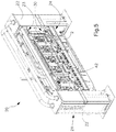
- the apparatus for making reinforcements for reinforced concrete according to the present invention is indicated in its entirety with 1.
- the reinforcements to be made are generically constituted, in a known way, by a series of longitudinal elements 2 joined by transverse elements 3 in a way as to make bidimensional or tridimensional net metal structures.
- Such longitudinal and transverse elements 2, 3 can be constituted indifferently by bars which are straight or folded or calendered at least once at least at one end, or otherwise profiled according to a closed profile with one or more overlappings.
- the longitudinal bars 2 and/or the transverse elements 3 can be equipped at one end or both ends with at least one fold 2a of suitable length, folded with respect to the longitudinal axis of the same bars 2 by a predetermined folding angle, for example squared as represented.
- the transverse elements 3 are constituted by polygonal-profiled stirrups but it is obviously possible to provide for the use of transverse irons shaped in any way, included straight irons.
- the apparatus 1 comprises a loading station 10 in correspondence of which are provided support means 11 for the longitudinal bars 2 arranged in series.
- support means 11 are preferably constituted by a series of rollers 12 arranged coplanar with parallel horizontal axis.
- the rollers 12 are mounted freely rotatable on respective bearing frames 13.
- the longitudinal bars 2 are prearranged, suitably distanced one another, on a substantially horizontal work plane defined by cited support means 11.
- the rollers 12 of the support means 11 allow the support and the shift of the longitudinal bars 2 according to a feed direction A axial to the same longitudinal bars 2 and reduce the effort of the same movement.
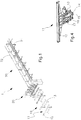
- the bearing frames 13 for the rollers 12 can be tilting on a longitudinal plane through articulation on a lower axis 14, hinged to a fixed base, as illustrated in fig. 4 .
- the tilting of the bearing frames 13 for the rollers is controlled by suitable actuator members 16 through a leverage 17.
- a joining station 20 downstream of the loading station 10 is arranged a joining station 20 in which is performed the joining of the longitudinal bars 2 to at least a transverse element 3, through welding.
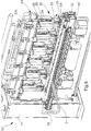
- the joining station 20 provides for a framework 21 substantially portal-shaped, defined by a couple of lateral columns 22 between which are arranged an upper crossbar 23 and a lower crossbar 24.
- the upper crossbar 23 frontally carries a guide 26, which basically extends for the total length of the same crossbar 23, on which are mounted a couple of supports 27 of the transverse element 3.
- the supports 27 have a position which is adjustable according to the dimensions of the transverse element 3.
- the supports 27 are constituted by outlined elements suitable to contain a single stirrup 3, open or closed, on a plane preferably vertical and orthogonal to the feed direction A of the longitudinal bars 2.
- stirrups 3 are loaded manually on the apparatus. Nevertheless it is possible to provide for the use of automatic loading devices, known per se, to simultaneously load the transverse elements 3. Particularly such automatic devices can operate the multiple loading of transverse elements having different diameter and/or length, in order to make particular types of metal reinforcements.
- the upper crossbar 23 Underneath the upper crossbar 23 are arranged guide means 25 along which a plurality of welding heads 30 are slidingly supported.
- the welding heads 30 are suitable to be shifted along the guide means 25, independently one another, upon activation of suitable movers 370.
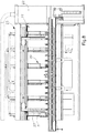
- the welding heads 30 can be shifted and pack collected on the outer parts of the upper crossbar 23 to allow the passage, in extraction step, of the metal structure in formation, as better described in the following (see fig. 10 ).
- the welding heads 30 are for example provided in a number equal to the longitudinal bars 2 to be welded. In effect it is yet possible to provide for the use of a number of welding heads smaller than the number of the longitudinal bars 2, providing for at least one thereof to be mobile along the upper crossbar 23 of the portal framework 21. It is also to be provided that a same welding head 30 can operate on more bars at the same time, in particular in the case in which these latter have a reduced diameter.
- the welding heads 30 provide for respective welder members constituted by a couple of electrodes 31, 37 made of adapted conductor material, suitably connected to a device for supplying the electric energy.
- each welding head 30 provides for a first upper electrode 31 and a second lower electrode 37, suitable to act in contraposition at the junction between the longitudinal bar 2 and the transverse element 3 to be welded, in a way as to carry out also the function of tightening the joint.
- Each welding head 30 further provides for a contact 32 that can be opened, arranged upstream of the electrodes 31, 37 according to the advancement direction A of the structure in formation, to close the electric circuit of the electrodes 31, 37 in contact with the lower crossbar 24 below (see figure 16 ).
- the electrodes 31, 37 and the contact 32 are preferably arranged offset one another, in substance on parallel longitudinal planes, in a way as to allow the passage of the longitudinal bars 2. Practically the longitudinal bars 2 are arranged in correspondence of the first electrode 31 of the relative welding head, at the side of the plane engaged by the contact 32.
- the first electrode 31 and the contact 32 are reciprocally connected through a flexible conductor 33 and are actionable singly, according to a vertical axis, by respective actuator members 34, 35 (see figure 6 ).
- the actuator members 34, 35 are carried at the lower part of a plate 36 sliding on guide means 25 along the upper crossbar 23 of the portal structure 21.
- the first electrode 31 and the contact 32 could be actuated through one only actuator member, with the interposition of a suitable elastic fastening element, for example a mechanical, pneumatic spring or the like.
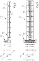
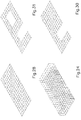
- the first electrode 31 is either carried overhang forward in the direction of the longitudinal elements 2, to insert profiled transverse elements 3 of any dimension or with a closed profile, or it is carried overhang transversally with respect to the same longitudinal elements 2, to allow the insertion of longitudinal elements 2 profiled with a closed profile (see figures 20 and 21 ). Alternately it is possible to provide for the electrode to be carried overhang in inclined direction to obtain both previous conditions.
- the lower crossbar 24 supports first and second support means 41, 42 for the longitudinal bars 2 fed to the joining station 20 to make the metal structure.
- the first support means 41 arranged in correspondence of the inlet zone of the joining station 20, are constituted by a series of raceways 43, constrained in adjustable positions, through respective fastening members 44, to a section bar 45 of the lower crossbar 24.
- the second support means 42 arranged in correspondence of the welding zone, are constituted by a series of forks 46, constrained in adjustable positions, through respective fastening members 47, to a further section bar 48 of the lower crossbar 24.
- each raceway 43 of the first support means 41 results longitudinally aligned with a respective fork 46 of the second support means 42, in a way as to allow the passage of a relative longitudinal bar 2.
- the first support means 41 is suitable to operate a roller 50 for containing the longitudinal bars 2, which extends in a direction transverse to the axis of the same longitudinal bars 2.
- the containment roller 50 is carried freely rotatable, in correspondence of the opposite ends, by plates 51 which are guided sliding along respective vertical guides 52 constrained to the columns 22 of the portal framework 21.
- the containment roller 50 is mobile in vertical direction, along the guides 52, upon control of suitable linear actuator members 53.
- the containment roller 50 allows to keep in position the longitudinal bars 2 inside the raceways 43, during the working, in particular to avoid the upsetting of longitudinal bars having a limited length.
- the joining station 20 also provides, substantially in correspondence of the lower crossbar 24, for a lifting roller 54 which extends in a direction transverse to the axis of the longitudinal bars 2 and arranged in use underneath the work plane on which are fed the same longitudinal bars 2, in a median position between the electrodes 31, 37 and the contact 32 of the welding heads 30.
- the lifting roller 54 is suitable to be shifted in vertical direction in a way as to operate the simultaneous lifting of the longitudinal bars 2. This allows in particular to insert the transverse elements 3 to be welded also under the longitudinal bars 2.
- the lower crossbar 24 further carries a plurality of support members 55 for the transverse elements 3 to be welded, in particular the lower branch of the stirrups.
- Such support members 55 have adjustable position along the lower crossbar 24, through relative supports 56, and are provided with magnetic members 57, for example magnets, to stably retain the transverse elements 3 in the correct position for joining to the longitudinal bars 2.
- the lower crossbar 24 can be lowered to allow the passage of the folds 2a directed downwards of the longitudinal bars 2. Alternately it is possible to provide for the possibility of raising the upper crossbar 23.
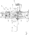
- the leveller device 60 With the joining station 20 is associated a leveller device 60 (see figures 7 and 11 ) arranged downstream of the welding zone, according to the advancement direction A of the metal structure in formation.
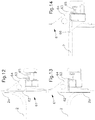
- the leveller device 60 provides a crossbar 63 made of outlined elements, on which are mounted, in adjustable positions, abutting members 61 which extend vertically above and underneath with respect to the cited work plane on which are fed the longitudinal bars 2, to abut single folds 2a of such bars 2 either in the case that they are oriented upwards or downwards.
- the abutting members 61 are constituted by listels 62 profiled with a vertical groove directed towards the longitudinal bars 2, carried integral by respective fork-shaped connections 64 suitable to be blocked on the crossbar 63 by means of relative screw members 65 (see figures 12 and 13 ).
- a further abutting member 66 constituted by a listel suitable to tip abut the straight longitudinal bars 2, devoid of folds at the anterior end ( fig. 14 ).
- the further abutting member 66 is arranged rear with respect to the abutting members 61, according to the advancement direction A of the longitudinal bars 2, to bring the anterior end of the longitudinal bars 2 level with respect to the transverse element 3 to which they are joined, substantially to the welding zone.
- the crossbar 63 of the leveller device 60 is carried at the opposite ends by a couple of carriages 67 which are mobile on respective vertical guides 68, under control of suitable vertical actuator members 69. This allows to shift the same leveller device 60 in a lowered idle position, at the end of its own operating step, to allow the advancing of the metal structure in formation.
- the apparatus Downstream of the joining station 20, the apparatus finally provides for an outlet station 70 of the metal structure in formation, provided with a haulage device 80.
- the outlet station 70 provides for a frame 71 extended longitudinally to the apparatus and provided with upper backstays 72 coplanar to the cited work plane of the loading station 10, in a way as to realize the continuity of such a plane on which advances the metal structure in formation.
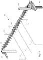
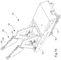
- the haulage device 80 provides for a carriage 81 which is mobile, by means of wheels 82 suitably motorised, on a wheel-track 73 which extends longitudinally to the apparatus, on a plane which lies lower to the cited work plane ( fig. 15 ). Obviously it is also possible to provide for the carriage 81 of the haulage device to operate above or in correspondence of the cited work plane. From the carriage 81 extends a frame 83 to which can be fixed, in positions adjustable in direction transverse to the longitudinal axis of the apparatus, single supports 84 of dragging members 85. Such dragging members 85 respectively provide for a tilting arm 86 articulated on a pin 87 in a way as to result rotatable on a longitudinal vertical plane, upon control of suitable actuator means. The tilting arm 86 bears at its free end a pliers element 88 suitable to seize preferably a transverse element 3 of the structure in formation.
- the haulage device 80 is provided with two dragging members 85, carrying respective pliers members 88, but it is obviously possible to provide for a different number of dragging members 85, according to the dimensions of the structure in formation.
- the method for making reinforcements for reinforced concrete provides for prearranging a series of longitudinal bars 2, suitably distanced between them, upon the work plane defined by the rollers 12 of the support means 11 of the same longitudinal bars 2, in correspondence of the loading station 10.
- the loading of the longitudinal bars 2 on the support means 11 can be carried out manually or with the aid of suitable automatic loader devices.
- the longitudinal bars 2 can be arranged in the desired number and at the desired reciprocal distances, according to the specific characteristics of the metal structure to be made; the longitudinal bars 2 can also respectively have different diameter and length, in the case that it is required by the project, upon suitable adjustment of the guide members.
- the longitudinal bras 2 are then fed, making them shift upon the aforesaid work plane, to the joining station 20 in correspondence of which are prearranged welding means 30.
- the longitudinal bars 2 cross the portal framework 21 of the joining station 20, respectively engaging the first and second support means 41, 42, and are brought abutting against the leveller device 60.
- a previous adjustment of the raceways 43 and of the forks 46 of the support means 41, 42 along the respective section bars 45, 48 of the lower crossbar 24 is obviously necessary.
- the raceways 43 and the forks 46 are blocked in the desired position through the respective fastening members 44, 47.
- the position of the abutting members 66 and 61 of the leveller device 60 is preventively adjusted, along the crossbar 63.
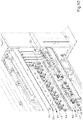
- the longitudinal bars 2 are brought abutting against the members 66 and 61 according to the fact that such bars 2 are straight or provided with folds 2a directed upwards or downwards, as schematically illustrated in fig. 11 .
- the bars 2 are frontally provided with folds directed upwards or downwards, these are inserted abutting against the vertical groove of the listel 62 of the abutting members 61 ( figures 12 and 13 ); instead, the straight longitudinal bars 2 are brought tip abutting against the abutting member 66 ( fig. 14 ).
- abutting members 61 also serve as vertical guide for the folds 2a of the longitudinal bars 2 that, in such a way, are maintained in the correct mounting position.
- a first transverse element 3, prearranged in the joining station 20, is joined to the longitudinal bars 2 by moving the welding means 30.
- the transverse element 3 is constituted by a polygonal stirrup inserted between the supports 27 of the portal structure 21 and brought into contact with its lower branch upon the longitudinal bars 2.
- the transverse elements 3 which are used can obviously be differently shaped, in particular being possible also the use of two or more transverse elements on the same vertical plane. Such transverse elements can also be different in diameter, length, pitch, geometric shape of the possible folds, nature of the material and the like.
- the welding of the stirrup 3 to the longitudinal bars 2 is performed operating the descent of the electrodes 31 of the welding heads 30, which are prearranged in the suitable work positions along the upper crossbar 23 of the portal structure 21.
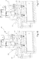
- each welding head 30 After each welding head 30 has been positioned in correspondence of the junction to be welded, it is provided to operate the descent of the contact 32 that can be opened on the lower crossbar 24 in a way as to allow the closing of the circuit ( fig. 16 ). Then, it is provided to operate the descent of the first upper electrode 31 which tightens the junction against the second lower electrode 37, performing the welding of the junction ( fig. 17 ). At the end of the welding, it is provided to operate the inverse raising movement of the electrode 31 and of the contact 32 to allow the shifting movement of the structure in formation ( fig. 18 ).
- the return of the welding heads 30 and of the containment roller 50 in the lifted position is operated, as well as the moving of the leveller device 60 in the idle lowered position, in a way as to allow the advancing of the forming metal structure on the work plane.
- the advancing is actuated by the haulage device 80 associated with the outlet station 70, according to a predetermined step corresponding to the fastening distance of a successive transverse element 3 to the longitudinal bars 2, as previously described.
- fastening of every provided transverse element 3 is carried out on the longitudinal bars 2, until completing the metal structure.
- the transverse elements 3 can be indifferently fastened above, under the longitudinal bars 2, in the second case due to the intervention of the raising roller 54 that allows the operator to insert the transverse element 3 from the down, between the lower electrodes and the longitudinal elements 2 that result raised with respect to the same lower electrodes. If furthermore the longitudinal bars 2 are provided with folds 2a in the back end directed upwards, lateral shifting of the welding heads 30 is also operated, as can be seen in fig. 9 , so that the same welding heads 30 do not interfere with the advancement of the forming metal structure or before the extraction of the item. Instead if the folds are directed downwards, in order to allow the extraction of the item it must be possible to lower the lower crossbar of the joining station.
- the contact 32 can be opened in order to allow the welding heads 30 to shift transversally from a longitudinal element 2 to another, to join more joints with the same welding head 30, for example in the case that the welding heads 30 are in a lower number than the longitudinal elements, or to shift all the welding heads 30 laterally, in order not to interfere with the possible folds 2a upwards at the end of the longitudinal elements 2, in the extraction step.
- the method and the described apparatus attain the scope of easily making reinforcements for reinforced concrete of different type, having either a bidimensional or a tridimensional structure. Practically it is possible to realize netting wire structures of any typology with respect to dimensions, shape and diameters of the longitudinal bars and of the transverse elements, pitch between the elements, presence or not of folds and other analogous parameters.
- FIGs 22 - 32 illustrate, for exemplifying purposes, a series of bidimensional and tridimensional metal structures that can be made by means of the claimed apparatus.
- figures 22 and 23 illustrate two examples of so-called 'parrillas' nets
- figures 24 and 25 illustrate two examples of nets with stirrups
- figure 26 illustrates an example of cage
- figure 27 illustrates an example of small ladder
- figures 28 and 29 illustrate two examples of nets, with longitudinal elements having straight and oblique levelling
- figures 30 and 31 illustrate two examples of nets for door and for door and window
- figure 32 illustrates an example of plinth or wall.
- the diameter of the irons can be equal of varying
- the pitch between the adjacent elements can be equal or varying
- the folds can be short or long and of equal or various length.
- transverse elements can be arranged above the longitudinal elements, as generally represented, but also under or possibly alternated.
- a characteristic of the described apparatus is given by the fact of allowing the realization of tridimensional metal structures starting from longitudinal and/or transverse elements with at least a fold at one or both ends. To such a result contributes specifically the characteristics of the apparatus for which the welding heads can be laterally shifted, in a way as to make the operative zone free for advancing the forming structure.
- Another important advantage of the claimed apparatus consists in the fact that it is possible to make wire nettings and other metal bidimensional or tridimensional structures also using longitudinal bras having different diameter, due to the possibility of adjusting and actuating singly in an independent way the welding heads.
- the embodiment of the invention may vary depending on the requirements.
Landscapes
- Engineering & Computer Science (AREA)
- Mechanical Engineering (AREA)
- Manufacturing & Machinery (AREA)
- Wire Processing (AREA)
- Reinforcement Elements For Buildings (AREA)
Applications Claiming Priority (2)
| Application Number | Priority Date | Filing Date | Title |
|---|---|---|---|
| ITBO2009A000100A IT1392866B1 (it) | 2009-02-20 | 2009-02-20 | Metodo e apparecchiatura per realizzare armature per cemento armato |
| PCT/IB2010/050578 WO2010095076A1 (en) | 2009-02-20 | 2010-02-09 | Method and apparatus for making reinforcements for reinforced concrete |
Publications (2)
| Publication Number | Publication Date |
|---|---|
| EP2398607A1 EP2398607A1 (en) | 2011-12-28 |
| EP2398607B1 true EP2398607B1 (en) | 2019-06-05 |
Family
ID=42154946
Family Applications (1)
| Application Number | Title | Priority Date | Filing Date |
|---|---|---|---|
| EP10705422.3A Active EP2398607B1 (en) | 2009-02-20 | 2010-02-09 | Method and apparatus for making reinforcements for reinforced concrete |
Country Status (3)
| Country | Link |
|---|---|
| EP (1) | EP2398607B1 (it) |
| IT (1) | IT1392866B1 (it) |
| WO (1) | WO2010095076A1 (it) |
Families Citing this family (2)
| Publication number | Priority date | Publication date | Assignee | Title |
|---|---|---|---|---|
| IT1403202B1 (it) * | 2010-12-23 | 2013-10-15 | Schnell Spa | Metodo e apparecchiatura per realizzare armature per cemento armato |
| AT520866B1 (de) * | 2018-01-29 | 2021-12-15 | Apilion Machines Services Gmbh | Widerstandsschweißvorrichtung sowie Verfahren zum Herstellen von Drahtnetzen |
Citations (3)
| Publication number | Priority date | Publication date | Assignee | Title |
|---|---|---|---|---|
| EP0162183A1 (fr) * | 1984-04-24 | 1985-11-27 | SISMO INTERNATIONAL personenvennootschap met beperkte aansprakelijkheid | Procédé d'assemblage de structures métalliques tridimensionelles, et machine pour leur réalisation |
| WO1993019868A1 (en) * | 1990-10-05 | 1993-10-14 | Pertti Tapio Ollilainen | A method for manufacturing a mesh reinforcement |
| WO2010052562A2 (en) * | 2008-11-07 | 2010-05-14 | Beta Systems Srl A Socio Unico | Machine for forming a metal mesh and relative welding unit |
Family Cites Families (6)
| Publication number | Priority date | Publication date | Assignee | Title |
|---|---|---|---|---|
| AU523559B2 (en) * | 1978-02-09 | 1982-08-05 | Rocla Concrete Pipes Ltd. | Concrete reinforcement |
| AT365492B (de) * | 1979-12-14 | 1982-01-25 | Evg Entwicklung Verwert Ges | Nach der elektrischen widerstandsmethode arbeitende vielpunkt-schweissmaschine zum herstellen von gittern aus laengs- und querdraehten |
| DE3245179C2 (de) * | 1982-12-07 | 1985-01-17 | Staco Stapelmann GmbH, 4044 Kaarst | Vorrichtung zum Herstellen von Gitterrosten |
| DE4031383A1 (de) * | 1990-10-04 | 1992-04-09 | Hugo Bittlmayer | Vorrichtung zum aufbringen und verbinden von vorgefertigten gittertraegern auf eine auf abstuetzungen ruhende vorgefertigte bewehrungsmatte |
| AT410290B (de) * | 2000-04-14 | 2003-03-25 | Progress Maschinen & Automatio | Verfahren zur herstellung von bewehrungskörben aus stahl |
| DK176331B1 (da) | 2002-07-23 | 2007-08-13 | Stema Engineering As | Fremgangsmåde og maskine til fremstilling af betonarmeringsrullenet |
-
2009
- 2009-02-20 IT ITBO2009A000100A patent/IT1392866B1/it active
-
2010
- 2010-02-09 EP EP10705422.3A patent/EP2398607B1/en active Active
- 2010-02-09 WO PCT/IB2010/050578 patent/WO2010095076A1/en not_active Ceased
Patent Citations (3)
| Publication number | Priority date | Publication date | Assignee | Title |
|---|---|---|---|---|
| EP0162183A1 (fr) * | 1984-04-24 | 1985-11-27 | SISMO INTERNATIONAL personenvennootschap met beperkte aansprakelijkheid | Procédé d'assemblage de structures métalliques tridimensionelles, et machine pour leur réalisation |
| WO1993019868A1 (en) * | 1990-10-05 | 1993-10-14 | Pertti Tapio Ollilainen | A method for manufacturing a mesh reinforcement |
| WO2010052562A2 (en) * | 2008-11-07 | 2010-05-14 | Beta Systems Srl A Socio Unico | Machine for forming a metal mesh and relative welding unit |
Also Published As
| Publication number | Publication date |
|---|---|
| EP2398607A1 (en) | 2011-12-28 |
| ITBO20090100A1 (it) | 2010-08-21 |
| WO2010095076A1 (en) | 2010-08-26 |
| IT1392866B1 (it) | 2012-04-02 |
Similar Documents
| Publication | Publication Date | Title |
|---|---|---|
| CN107253053B (zh) | 整体式焊网机 | |
| KR101630184B1 (ko) | 철근트러스조립체 자동생산장치 | |
| EP0933161A1 (en) | Device for assembling motor-vehicle bodies by spot-welding | |
| CN110666080A (zh) | 折弯焊接线 | |
| KR102264022B1 (ko) | 철망 절곡장치 | |
| KR102358140B1 (ko) | 철망 절곡장치 | |
| CN216029294U (zh) | 一种裙板卷圆焊接设备 | |
| CZ219693A3 (en) | Process and apparatus for producing reinforced matting | |
| CN216421641U (zh) | 原位焊接卷圆的一种裙板卷圆焊接设备 | |
| CN106391945A (zh) | 一种新型焊网机 | |
| KR102087725B1 (ko) | 철근 구조물 자동 용접 장치 | |
| EP1378302B1 (en) | Method and apparatus for forming metal frames for reinforced concrete | |
| EP2398607B1 (en) | Method and apparatus for making reinforcements for reinforced concrete | |
| KR101666355B1 (ko) | 수로관에 내장되는 용접철망의 철선 용접 및 성형장치 | |
| CN212525829U (zh) | 一种钢筋网片焊接设备 | |
| KR101051891B1 (ko) | 앵커세트용 브라켓 제조장치 | |
| CN111673017B (zh) | 一种异形钢筋网片焊接设备 | |
| KR102534179B1 (ko) | 메쉬 공급 가이드를 구비한 철망 절곡장치 | |
| CN216730171U (zh) | 改进的裙板卷圆焊接设备 | |
| WO2005032742A1 (en) | Apparatus for and method of manufacturing wire-net | |
| US20120193032A1 (en) | Installation and process for making panels | |
| EP2908962B1 (en) | Method and apparatus for folding metal rods in bars | |
| CN115070434B (zh) | 一种断桥生产方法及断桥半自动生产线 | |
| CN210997011U (zh) | 复合箍筋焊机结构 | |
| WO2002057045A1 (en) | Welding assembly for cage-forming machine and connected welding method |
Legal Events
| Date | Code | Title | Description |
|---|---|---|---|
| PUAI | Public reference made under article 153(3) epc to a published international application that has entered the european phase |
Free format text: ORIGINAL CODE: 0009012 |
|
| 17P | Request for examination filed |
Effective date: 20110916 |
|
| AK | Designated contracting states |
Kind code of ref document: A1 Designated state(s): AT BE BG CH CY CZ DE DK EE ES FI FR GB GR HR HU IE IS IT LI LT LU LV MC MK MT NL NO PL PT RO SE SI SK SM TR |
|
| DAX | Request for extension of the european patent (deleted) | ||
| STAA | Information on the status of an ep patent application or granted ep patent |
Free format text: STATUS: EXAMINATION IS IN PROGRESS |
|
| 17Q | First examination report despatched |
Effective date: 20170804 |
|
| RAP1 | Party data changed (applicant data changed or rights of an application transferred) |
Owner name: SCHNELL S.P.A. |
|
| GRAP | Despatch of communication of intention to grant a patent |
Free format text: ORIGINAL CODE: EPIDOSNIGR1 |
|
| STAA | Information on the status of an ep patent application or granted ep patent |
Free format text: STATUS: GRANT OF PATENT IS INTENDED |
|
| INTG | Intention to grant announced |
Effective date: 20181219 |
|
| GRAS | Grant fee paid |
Free format text: ORIGINAL CODE: EPIDOSNIGR3 |
|
| GRAA | (expected) grant |
Free format text: ORIGINAL CODE: 0009210 |
|
| STAA | Information on the status of an ep patent application or granted ep patent |
Free format text: STATUS: THE PATENT HAS BEEN GRANTED |
|
| AK | Designated contracting states |
Kind code of ref document: B1 Designated state(s): AT BE BG CH CY CZ DE DK EE ES FI FR GB GR HR HU IE IS IT LI LT LU LV MC MK MT NL NO PL PT RO SE SI SK SM TR |
|
| REG | Reference to a national code |
Ref country code: GB Ref legal event code: FG4D |
|
| REG | Reference to a national code |
Ref country code: CH Ref legal event code: EP |
|
| REG | Reference to a national code |
Ref country code: AT Ref legal event code: REF Ref document number: 1139486 Country of ref document: AT Kind code of ref document: T Effective date: 20190615 |
|
| REG | Reference to a national code |
Ref country code: IE Ref legal event code: FG4D |
|
| REG | Reference to a national code |
Ref country code: DE Ref legal event code: R096 Ref document number: 602010059242 Country of ref document: DE |
|
| REG | Reference to a national code |
Ref country code: CH Ref legal event code: NV Representative=s name: IP PARTNERS J. WENGER, CH |
|
| REG | Reference to a national code |
Ref country code: NL Ref legal event code: MP Effective date: 20190605 |
|
| REG | Reference to a national code |
Ref country code: LT Ref legal event code: MG4D |
|
| PG25 | Lapsed in a contracting state [announced via postgrant information from national office to epo] |
Ref country code: NO Free format text: LAPSE BECAUSE OF FAILURE TO SUBMIT A TRANSLATION OF THE DESCRIPTION OR TO PAY THE FEE WITHIN THE PRESCRIBED TIME-LIMIT Effective date: 20190905 Ref country code: HR Free format text: LAPSE BECAUSE OF FAILURE TO SUBMIT A TRANSLATION OF THE DESCRIPTION OR TO PAY THE FEE WITHIN THE PRESCRIBED TIME-LIMIT Effective date: 20190605 Ref country code: SE Free format text: LAPSE BECAUSE OF FAILURE TO SUBMIT A TRANSLATION OF THE DESCRIPTION OR TO PAY THE FEE WITHIN THE PRESCRIBED TIME-LIMIT Effective date: 20190605 Ref country code: FI Free format text: LAPSE BECAUSE OF FAILURE TO SUBMIT A TRANSLATION OF THE DESCRIPTION OR TO PAY THE FEE WITHIN THE PRESCRIBED TIME-LIMIT Effective date: 20190605 Ref country code: LT Free format text: LAPSE BECAUSE OF FAILURE TO SUBMIT A TRANSLATION OF THE DESCRIPTION OR TO PAY THE FEE WITHIN THE PRESCRIBED TIME-LIMIT Effective date: 20190605 Ref country code: ES Free format text: LAPSE BECAUSE OF FAILURE TO SUBMIT A TRANSLATION OF THE DESCRIPTION OR TO PAY THE FEE WITHIN THE PRESCRIBED TIME-LIMIT Effective date: 20190605 |
|
| PG25 | Lapsed in a contracting state [announced via postgrant information from national office to epo] |
Ref country code: BG Free format text: LAPSE BECAUSE OF FAILURE TO SUBMIT A TRANSLATION OF THE DESCRIPTION OR TO PAY THE FEE WITHIN THE PRESCRIBED TIME-LIMIT Effective date: 20190905 Ref country code: LV Free format text: LAPSE BECAUSE OF FAILURE TO SUBMIT A TRANSLATION OF THE DESCRIPTION OR TO PAY THE FEE WITHIN THE PRESCRIBED TIME-LIMIT Effective date: 20190605 |
|
| REG | Reference to a national code |
Ref country code: GR Ref legal event code: EP Ref document number: 20190402690 Country of ref document: GR Effective date: 20191128 |
|
| PG25 | Lapsed in a contracting state [announced via postgrant information from national office to epo] |
Ref country code: SK Free format text: LAPSE BECAUSE OF FAILURE TO SUBMIT A TRANSLATION OF THE DESCRIPTION OR TO PAY THE FEE WITHIN THE PRESCRIBED TIME-LIMIT Effective date: 20190605 Ref country code: RO Free format text: LAPSE BECAUSE OF FAILURE TO SUBMIT A TRANSLATION OF THE DESCRIPTION OR TO PAY THE FEE WITHIN THE PRESCRIBED TIME-LIMIT Effective date: 20190605 Ref country code: CZ Free format text: LAPSE BECAUSE OF FAILURE TO SUBMIT A TRANSLATION OF THE DESCRIPTION OR TO PAY THE FEE WITHIN THE PRESCRIBED TIME-LIMIT Effective date: 20190605 Ref country code: EE Free format text: LAPSE BECAUSE OF FAILURE TO SUBMIT A TRANSLATION OF THE DESCRIPTION OR TO PAY THE FEE WITHIN THE PRESCRIBED TIME-LIMIT Effective date: 20190605 Ref country code: NL Free format text: LAPSE BECAUSE OF FAILURE TO SUBMIT A TRANSLATION OF THE DESCRIPTION OR TO PAY THE FEE WITHIN THE PRESCRIBED TIME-LIMIT Effective date: 20190605 Ref country code: PT Free format text: LAPSE BECAUSE OF FAILURE TO SUBMIT A TRANSLATION OF THE DESCRIPTION OR TO PAY THE FEE WITHIN THE PRESCRIBED TIME-LIMIT Effective date: 20191007 |
|
| PG25 | Lapsed in a contracting state [announced via postgrant information from national office to epo] |
Ref country code: SM Free format text: LAPSE BECAUSE OF FAILURE TO SUBMIT A TRANSLATION OF THE DESCRIPTION OR TO PAY THE FEE WITHIN THE PRESCRIBED TIME-LIMIT Effective date: 20190605 Ref country code: IS Free format text: LAPSE BECAUSE OF FAILURE TO SUBMIT A TRANSLATION OF THE DESCRIPTION OR TO PAY THE FEE WITHIN THE PRESCRIBED TIME-LIMIT Effective date: 20191005 |
|
| REG | Reference to a national code |
Ref country code: DE Ref legal event code: R097 Ref document number: 602010059242 Country of ref document: DE |
|
| PG25 | Lapsed in a contracting state [announced via postgrant information from national office to epo] |
Ref country code: TR Free format text: LAPSE BECAUSE OF FAILURE TO SUBMIT A TRANSLATION OF THE DESCRIPTION OR TO PAY THE FEE WITHIN THE PRESCRIBED TIME-LIMIT Effective date: 20190605 |
|
| PLBE | No opposition filed within time limit |
Free format text: ORIGINAL CODE: 0009261 |
|
| STAA | Information on the status of an ep patent application or granted ep patent |
Free format text: STATUS: NO OPPOSITION FILED WITHIN TIME LIMIT |
|
| PG25 | Lapsed in a contracting state [announced via postgrant information from national office to epo] |
Ref country code: PL Free format text: LAPSE BECAUSE OF FAILURE TO SUBMIT A TRANSLATION OF THE DESCRIPTION OR TO PAY THE FEE WITHIN THE PRESCRIBED TIME-LIMIT Effective date: 20190605 Ref country code: DK Free format text: LAPSE BECAUSE OF FAILURE TO SUBMIT A TRANSLATION OF THE DESCRIPTION OR TO PAY THE FEE WITHIN THE PRESCRIBED TIME-LIMIT Effective date: 20190605 |
|
| 26N | No opposition filed |
Effective date: 20200306 |
|
| PG25 | Lapsed in a contracting state [announced via postgrant information from national office to epo] |
Ref country code: SI Free format text: LAPSE BECAUSE OF FAILURE TO SUBMIT A TRANSLATION OF THE DESCRIPTION OR TO PAY THE FEE WITHIN THE PRESCRIBED TIME-LIMIT Effective date: 20190605 |
|
| REG | Reference to a national code |
Ref country code: DE Ref legal event code: R119 Ref document number: 602010059242 Country of ref document: DE |
|
| REG | Reference to a national code |
Ref country code: CH Ref legal event code: PL |
|
| GBPC | Gb: european patent ceased through non-payment of renewal fee |
Effective date: 20200209 |
|
| REG | Reference to a national code |
Ref country code: BE Ref legal event code: MM Effective date: 20200229 |
|
| PG25 | Lapsed in a contracting state [announced via postgrant information from national office to epo] |
Ref country code: GR Free format text: LAPSE BECAUSE OF NON-PAYMENT OF DUE FEES Effective date: 20200909 Ref country code: LU Free format text: LAPSE BECAUSE OF NON-PAYMENT OF DUE FEES Effective date: 20200209 Ref country code: MC Free format text: LAPSE BECAUSE OF FAILURE TO SUBMIT A TRANSLATION OF THE DESCRIPTION OR TO PAY THE FEE WITHIN THE PRESCRIBED TIME-LIMIT Effective date: 20190605 |
|
| PG25 | Lapsed in a contracting state [announced via postgrant information from national office to epo] |
Ref country code: CH Free format text: LAPSE BECAUSE OF NON-PAYMENT OF DUE FEES Effective date: 20200229 Ref country code: LI Free format text: LAPSE BECAUSE OF NON-PAYMENT OF DUE FEES Effective date: 20200229 |
|
| PG25 | Lapsed in a contracting state [announced via postgrant information from national office to epo] |
Ref country code: FR Free format text: LAPSE BECAUSE OF NON-PAYMENT OF DUE FEES Effective date: 20200229 Ref country code: IE Free format text: LAPSE BECAUSE OF NON-PAYMENT OF DUE FEES Effective date: 20200209 Ref country code: DE Free format text: LAPSE BECAUSE OF NON-PAYMENT OF DUE FEES Effective date: 20200901 Ref country code: GB Free format text: LAPSE BECAUSE OF NON-PAYMENT OF DUE FEES Effective date: 20200209 |
|
| PG25 | Lapsed in a contracting state [announced via postgrant information from national office to epo] |
Ref country code: BE Free format text: LAPSE BECAUSE OF NON-PAYMENT OF DUE FEES Effective date: 20200229 |
|
| REG | Reference to a national code |
Ref country code: AT Ref legal event code: MM01 Ref document number: 1139486 Country of ref document: AT Kind code of ref document: T Effective date: 20200209 |
|
| PG25 | Lapsed in a contracting state [announced via postgrant information from national office to epo] |
Ref country code: AT Free format text: LAPSE BECAUSE OF NON-PAYMENT OF DUE FEES Effective date: 20200209 |
|
| PG25 | Lapsed in a contracting state [announced via postgrant information from national office to epo] |
Ref country code: IT Free format text: LAPSE BECAUSE OF NON-PAYMENT OF DUE FEES Effective date: 20200209 |
|
| PG25 | Lapsed in a contracting state [announced via postgrant information from national office to epo] |
Ref country code: MT Free format text: LAPSE BECAUSE OF FAILURE TO SUBMIT A TRANSLATION OF THE DESCRIPTION OR TO PAY THE FEE WITHIN THE PRESCRIBED TIME-LIMIT Effective date: 20190605 Ref country code: CY Free format text: LAPSE BECAUSE OF FAILURE TO SUBMIT A TRANSLATION OF THE DESCRIPTION OR TO PAY THE FEE WITHIN THE PRESCRIBED TIME-LIMIT Effective date: 20190605 |
|
| PG25 | Lapsed in a contracting state [announced via postgrant information from national office to epo] |
Ref country code: MK Free format text: LAPSE BECAUSE OF FAILURE TO SUBMIT A TRANSLATION OF THE DESCRIPTION OR TO PAY THE FEE WITHIN THE PRESCRIBED TIME-LIMIT Effective date: 20190605 |
|
| REG | Reference to a national code |
Ref country code: AT Ref legal event code: UEP Ref document number: 1139486 Country of ref document: AT Kind code of ref document: T Effective date: 20190605 |