EP2398672B1 - Dispositif de détection destiné à déterminer l'écart de la position d'un appui-tête par rapport à une position prescrite - Google Patents
Dispositif de détection destiné à déterminer l'écart de la position d'un appui-tête par rapport à une position prescrite Download PDFInfo
- Publication number
- EP2398672B1 EP2398672B1 EP10708699.3A EP10708699A EP2398672B1 EP 2398672 B1 EP2398672 B1 EP 2398672B1 EP 10708699 A EP10708699 A EP 10708699A EP 2398672 B1 EP2398672 B1 EP 2398672B1
- Authority
- EP
- European Patent Office
- Prior art keywords
- headrest
- control unit
- deviation
- head
- sensor device
- Prior art date
- Legal status (The legal status is an assumption and is not a legal conclusion. Google has not performed a legal analysis and makes no representation as to the accuracy of the status listed.)
- Not-in-force
Links
- 230000005684 electric field Effects 0.000 claims description 9
- 230000015572 biosynthetic process Effects 0.000 claims description 4
- 238000001514 detection method Methods 0.000 description 6
- 238000000034 method Methods 0.000 description 4
- 230000004069 differentiation Effects 0.000 description 2
- 238000006073 displacement reaction Methods 0.000 description 2
- 206010019196 Head injury Diseases 0.000 description 1
- 208000027418 Wounds and injury Diseases 0.000 description 1
- 230000003213 activating effect Effects 0.000 description 1
- 238000004364 calculation method Methods 0.000 description 1
- 239000003990 capacitor Substances 0.000 description 1
- 230000009514 concussion Effects 0.000 description 1
- 230000006378 damage Effects 0.000 description 1
- 238000010586 diagram Methods 0.000 description 1
- 230000000694 effects Effects 0.000 description 1
- 238000011156 evaluation Methods 0.000 description 1
- 230000004886 head movement Effects 0.000 description 1
- 208000014674 injury Diseases 0.000 description 1
- 238000009434 installation Methods 0.000 description 1
- 230000010354 integration Effects 0.000 description 1
- 239000000463 material Substances 0.000 description 1
- 238000005259 measurement Methods 0.000 description 1
- 230000000704 physical effect Effects 0.000 description 1
- 238000005293 physical law Methods 0.000 description 1
- 230000002441 reversible effect Effects 0.000 description 1
- 238000011144 upstream manufacturing Methods 0.000 description 1
- 230000000007 visual effect Effects 0.000 description 1
Images
Classifications
-
- G—PHYSICS
- G01—MEASURING; TESTING
- G01B—MEASURING LENGTH, THICKNESS OR SIMILAR LINEAR DIMENSIONS; MEASURING ANGLES; MEASURING AREAS; MEASURING IRREGULARITIES OF SURFACES OR CONTOURS
- G01B7/00—Measuring arrangements characterised by the use of electric or magnetic techniques
- G01B7/003—Measuring arrangements characterised by the use of electric or magnetic techniques for measuring position, not involving coordinate determination
-
- B—PERFORMING OPERATIONS; TRANSPORTING
- B60—VEHICLES IN GENERAL
- B60N—SEATS SPECIALLY ADAPTED FOR VEHICLES; VEHICLE PASSENGER ACCOMMODATION NOT OTHERWISE PROVIDED FOR
- B60N2/00—Seats specially adapted for vehicles; Arrangement or mounting of seats in vehicles
- B60N2/002—Seats provided with an occupancy detection means mounted therein or thereon
- B60N2/0021—Seats provided with an occupancy detection means mounted therein or thereon characterised by the type of sensor or measurement
- B60N2/0024—Seats provided with an occupancy detection means mounted therein or thereon characterised by the type of sensor or measurement for identifying, categorising or investigation of the occupant or object on the seat
- B60N2/0027—Seats provided with an occupancy detection means mounted therein or thereon characterised by the type of sensor or measurement for identifying, categorising or investigation of the occupant or object on the seat for detecting the position of the occupant or of occupant's body part
- B60N2/0028—Seats provided with an occupancy detection means mounted therein or thereon characterised by the type of sensor or measurement for identifying, categorising or investigation of the occupant or object on the seat for detecting the position of the occupant or of occupant's body part of a body part, e.g. of an arm or a leg
-
- B—PERFORMING OPERATIONS; TRANSPORTING
- B60—VEHICLES IN GENERAL
- B60N—SEATS SPECIALLY ADAPTED FOR VEHICLES; VEHICLE PASSENGER ACCOMMODATION NOT OTHERWISE PROVIDED FOR
- B60N2/00—Seats specially adapted for vehicles; Arrangement or mounting of seats in vehicles
- B60N2/002—Seats provided with an occupancy detection means mounted therein or thereon
- B60N2/0021—Seats provided with an occupancy detection means mounted therein or thereon characterised by the type of sensor or measurement
- B60N2/003—Seats provided with an occupancy detection means mounted therein or thereon characterised by the type of sensor or measurement characterised by the sensor mounting location in or on the seat
-
- B—PERFORMING OPERATIONS; TRANSPORTING
- B60—VEHICLES IN GENERAL
- B60N—SEATS SPECIALLY ADAPTED FOR VEHICLES; VEHICLE PASSENGER ACCOMMODATION NOT OTHERWISE PROVIDED FOR
- B60N2/00—Seats specially adapted for vehicles; Arrangement or mounting of seats in vehicles
- B60N2/02—Seats specially adapted for vehicles; Arrangement or mounting of seats in vehicles the seat or part thereof being movable, e.g. adjustable
- B60N2/0224—Non-manual adjustments, e.g. with electrical operation
- B60N2/02246—Electric motors therefor
-
- B—PERFORMING OPERATIONS; TRANSPORTING
- B60—VEHICLES IN GENERAL
- B60N—SEATS SPECIALLY ADAPTED FOR VEHICLES; VEHICLE PASSENGER ACCOMMODATION NOT OTHERWISE PROVIDED FOR
- B60N2/00—Seats specially adapted for vehicles; Arrangement or mounting of seats in vehicles
- B60N2/02—Seats specially adapted for vehicles; Arrangement or mounting of seats in vehicles the seat or part thereof being movable, e.g. adjustable
- B60N2/0224—Non-manual adjustments, e.g. with electrical operation
- B60N2/0244—Non-manual adjustments, e.g. with electrical operation with logic circuits
- B60N2/0268—Non-manual adjustments, e.g. with electrical operation with logic circuits using sensors or detectors for adapting the seat or seat part, e.g. to the position of an occupant
-
- B—PERFORMING OPERATIONS; TRANSPORTING
- B60—VEHICLES IN GENERAL
- B60N—SEATS SPECIALLY ADAPTED FOR VEHICLES; VEHICLE PASSENGER ACCOMMODATION NOT OTHERWISE PROVIDED FOR
- B60N2/00—Seats specially adapted for vehicles; Arrangement or mounting of seats in vehicles
- B60N2/80—Head-rests
- B60N2/806—Head-rests movable or adjustable
- B60N2/809—Head-rests movable or adjustable vertically slidable
-
- B—PERFORMING OPERATIONS; TRANSPORTING
- B60—VEHICLES IN GENERAL
- B60N—SEATS SPECIALLY ADAPTED FOR VEHICLES; VEHICLE PASSENGER ACCOMMODATION NOT OTHERWISE PROVIDED FOR
- B60N2/00—Seats specially adapted for vehicles; Arrangement or mounting of seats in vehicles
- B60N2/80—Head-rests
- B60N2/806—Head-rests movable or adjustable
- B60N2/865—Head-rests movable or adjustable providing a fore-and-aft movement with respect to the occupant's head
-
- G—PHYSICS
- G01—MEASURING; TESTING
- G01B—MEASURING LENGTH, THICKNESS OR SIMILAR LINEAR DIMENSIONS; MEASURING ANGLES; MEASURING AREAS; MEASURING IRREGULARITIES OF SURFACES OR CONTOURS
- G01B7/00—Measuring arrangements characterised by the use of electric or magnetic techniques
- G01B7/02—Measuring arrangements characterised by the use of electric or magnetic techniques for measuring length, width or thickness
- G01B7/023—Measuring arrangements characterised by the use of electric or magnetic techniques for measuring length, width or thickness for measuring distance between sensor and object
-
- G—PHYSICS
- G01—MEASURING; TESTING
- G01V—GEOPHYSICS; GRAVITATIONAL MEASUREMENTS; DETECTING MASSES OR OBJECTS; TAGS
- G01V3/00—Electric or magnetic prospecting or detecting; Measuring magnetic field characteristics of the earth, e.g. declination, deviation
- G01V3/08—Electric or magnetic prospecting or detecting; Measuring magnetic field characteristics of the earth, e.g. declination, deviation operating with magnetic or electric fields produced or modified by objects or geological structures or by detecting devices
- G01V3/088—Electric or magnetic prospecting or detecting; Measuring magnetic field characteristics of the earth, e.g. declination, deviation operating with magnetic or electric fields produced or modified by objects or geological structures or by detecting devices operating with electric fields
-
- B—PERFORMING OPERATIONS; TRANSPORTING
- B60—VEHICLES IN GENERAL
- B60N—SEATS SPECIALLY ADAPTED FOR VEHICLES; VEHICLE PASSENGER ACCOMMODATION NOT OTHERWISE PROVIDED FOR
- B60N2210/00—Sensor types, e.g. for passenger detection systems or for controlling seats
- B60N2210/10—Field detection presence sensors
- B60N2210/12—Capacitive; Electric field
-
- B—PERFORMING OPERATIONS; TRANSPORTING
- B60—VEHICLES IN GENERAL
- B60N—SEATS SPECIALLY ADAPTED FOR VEHICLES; VEHICLE PASSENGER ACCOMMODATION NOT OTHERWISE PROVIDED FOR
- B60N2220/00—Computerised treatment of data for controlling of seats
- B60N2220/20—Computerised treatment of data for controlling of seats using a deterministic algorithm
Definitions
- the invention relates to a sensor device for determining the deviation of the position of a headrest of a motor vehicle seat from a desired position.
- Headrests are used in the context of a motor vehicle seat to support the head of a vehicle occupant using the seat in the event of a crash and thus to avoid kinking of the cervical spine to the rear.
- the security gain achieved by the head restraint is fully achieved, however, only when the head restraint is adjusted to the correct height with respect to the vertical head position, so that the head in the event of a crash substantially hits a center of the head rest intended for this purpose.
- An incorrectly adjusted headrest can lead to injuries in the neck and head area in the event of a crash.
- the headrest should also be arranged in the horizontal direction as close to the head of the vehicle occupant, but still allow unhindered head movement.
- a headrest For the correct positioning of a headrest this is usually adjustable in the vertical direction, as well as partially in the horizontal direction with respect to the seat back. In a high-quality motor vehicle seat, the adjustment of the headrest is often motorized.
- a modern headrest adjustment device is sometimes associated with a sensor device which detects the head position of a vehicle occupant with respect to the associated headrest.
- a sensor device which detects the head position of a vehicle occupant with respect to the associated headrest.
- This proximity sensor comprises three electrodes which are spaced apart from one another in the vertical direction Front of the headrest are arranged.
- the two outer electrodes serve here as transmitting electrodes for the emission of an alternating electric field in a space arranged in front of the headrest space.
- the middle electrode serves as a common receiving electrode for measuring the capacitance formed between each of the transmitting electrodes and the receiving electrode.
- the known adjusting device utilizes the physical effect that the capacitance of the electrode arrangement changes in a characteristic manner due to the presence of the head in the alternating electric field.
- the deviation of the headrest position from a predetermined vertical desired position with respect to the head of the vehicle occupant is determined by comparing the respective capacitance values assigned to the two transmitting electrodes. In this case, the headrest position in which these capacitance values are identical is recognized as the setpoint position for the headrest.
- Similar sensor devices with a capacitive proximity sensor, each comprising three electrodes, for detecting the head position in a headrest are also also made FR 2 884 775 A1 and DE 199 16 804 C1 known.
- the invention has for its object to provide a contrast improved sensor device for a headrest.
- the provided for determining the positional deviation of a headrest of a motor vehicle seat from a target position sensor device then comprises an integrated into the headrest or provided for integration in the headrest capacitive proximity sensor, said proximity sensor two with vertical Contains spaced transmitting electrodes and a common receiving electrode, which is preferably arranged approximately centrally between the two transmitting electrodes.
- the sensor device further comprises a control unit. This control unit is - circuit technology or program technology - set up to control the transmitting electrodes to emit an alternating electric field.
- the control unit is further configured to receive electrical signals received from the receiving electrode be detected, and each containing information about the capacitance formed between one of the transmitting electrodes and the common receiving electrode, and in the course of this evaluation, a measure of the vertical and horizontal deviation of the head restraint position from a predetermined position with respect to the position of the head of a vehicle occupant desired position to determine.
- the control unit is further configured to determine the measure of the vertical deviation of the head restraint position based on a difference between the two transmitting electrodes respectively associated with received signals, and to determine the measure of the horizontal deviation of the head restraint position based on a sum of these received signals.
- the control unit may also be set up to use quantities derived from these received signals instead of the received signals for the sum or difference formation.
- the control unit determined in an advantageous embodiment of the invention, the measure of the vertical deviation of the headrest position by subtraction of two derived from the received signals capacitance values, which are each assigned to one of the two transmitting electrodes.
- the control unit also determines the measure for the horizontal deviation of the headrest position, preferably by summation over these two capacitance values.
- the summation and / or subtraction is carried out optionally by means of circuitry at the hardware level, for example by means of (in particular analog) differentiation or adder circuits, or by program-technical means, i. on the software level by numerical summation or differentiation of digitized measurands.
- circuitry at the hardware level for example by means of (in particular analog) differentiation or adder circuits, or by program-technical means, i. on the software level by numerical summation or differentiation of digitized measurands.
- the invention can also be applied to a sensor device whose capacitive proximity sensor comprises two receiving electrodes arranged at a vertical distance from each other and one - in particular center - between this arranged common transmitting electrode comprises.
- the control unit is set up to control the common transmitting electrode for emitting the alternating electric field and to evaluate the electrical received signals detected here by the two receiving electrodes in the manner described above.
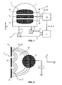
- Fig. 1 shows - roughly schematically simplified - a headrest 1 of a (not shown) motor vehicle seat.
- the headrest 1 is supported in a conventional manner at the upper end of the seat back of the motor vehicle seat and reversible to this seat back in a vertical direction z and independently thereof and in turn reversibly in a horizontal direction x ( Fig. 2 ) adjustable.
- the vertical direction z is arranged at least substantially perpendicular with respect to the surrounding space. It can also be slightly inclined with respect to the verticals of the room.
- the horizontal direction x is approximately parallel to the longitudinal axis of the motor vehicle and with built-in motor vehicle seat thus aligned parallel to the direction of travel.
- the horizontal direction x can be slightly inclined relative to the horizontal space.
- the vertical direction z and the horizontal direction x are approximately perpendicular to one another. In the illustration according to Fig. 1 the horizontal direction x is arranged perpendicular to the plane of the drawing.
- the headrest 1 can be adjusted by means of an associated adjusting device 2 by motor both in the vertical direction z and in the horizontal direction x.
- the adjusting device 2 comprises a first servomotor 3 which is connected to the headrest 1 for vertical adjustment of the headrest 1 via an associated adjusting mechanism 4.
- the adjusting device 2 comprises a further servomotor 5, which in turn acts on the headrest 1 via an associated adjusting mechanism 6.
- the servomotor 3 is arranged in particular in the seat back of the vehicle seat and acts on the adjusting mechanism 4 on spars, with which the headrest 1 is anchored in the usual way in the seat back.
- the servo motor 5, however, is preferably integrated in the headrest 1, wherein on the associated adjusting mechanism 6, a forward facing front part of the headrest 1 relative to a seat back anchored to the back of the headrest 1 is horizontally adjustable.
- the adjusting device 2 comprises an associated motor control unit 7, e.g. is essentially formed by a microcontroller with control software implemented therein, and which drives the servo motors 3 and 5 by outputting a respectively corresponding control current I1 and I2.
- an associated motor control unit 7 e.g. is essentially formed by a microcontroller with control software implemented therein, and which drives the servo motors 3 and 5 by outputting a respectively corresponding control current I1 and I2.
- the headrest 1 assigned to this seat is intended to be set to a vertical setpoint position at which the eye-ear line of the head K (FIG. Fig. 2 ) of the seat occupant is arranged approximately at a height with the surface center of the headrest 1.
- the headrest 1 is intended to be set to a horizontal desired position, in which the distance between the headrest 1 and the head K is a maximum of 5 cm, preferably about 2 cm to 3 cm.
- the sensor device 10 comprises a capacitive proximity sensor 11.
- This proximity sensor 11 is formed from three elongated electrode strips of conductive, flexible material, which are integrated on a front surface of the headrest 1 in this. These electrode strips are arranged parallel with respect to their longitudinal extension and at a distance above each other and comprise a bottom arranged transmitting electrode 12, a topmost arranged further transmitting electrode 13 and a common receiving electrode 14, which is arranged centrally and at a distance between the two transmitting electrodes 12 and 13.
- the sensor device 10 further comprises a sensor control unit 15, which in turn is formed by a microcontroller or an ASIC and is preferably integrated in the headrest 1.
- the sensor device 15 controls the transmitting electrodes 12 and 13 in the time division multiplexing method, ie alternating in time, each with an alternating voltage U1 or U2, on the basis of which the transmitting electrodes 12 and 13 in a space 16 upstream of the proximity sensor 11 (FIG. Fig. 2 ) each generate an alternating electric field F1 or F2.
- the spatial course of these alternating fields F1 and F2 is in Fig. 2 roughly shown schematically.
- Fig. 2 It can be seen that each transmitting electrode 12 and 13 with the common receiving electrode 14 forms a capacitor which is characterized in the electrical sense by a capacitance C1 or C2.
- the head K of the vehicle occupant occupying the vehicle seat also acts to some extent as counterelectrode to the transmitting electrodes 12 and 13 due to the grounding of the human body always present to a certain extent and due to this effect a proportion of each between each of the transmitting electrodes 12 and 13 and the receiving electrode 14 formed field F1 or F2 subtracts.
- the measurable capacitances C1 and C2 are thereby lowered, and the stronger, the closer the head K of the respective associated transmitting electrode 12 or 13 is.
- the sensor control unit 15 detects received signals E1 and E2 in the form of electrical voltages and currents which are generated in the receiving electrode 14 under the influence of the alternating electric fields F1 and F2.
- the sensor control unit 15 calculates, from the received signals E1 and E2, respectively the allocated capacitance C1 or C2 and determines therefrom a measure of the vertical deviation of the current headrest position from the vertical desired position (hereinafter referred to as vertical deviation amount ⁇ z), as well as a measure of the horizontal deviation the current head rest position from the horizontal target position (hereinafter referred to as horizontal deviation amount ⁇ x).
- the sensor control unit 15 controls a visual and / or audible indication in accordance with the deviation amounts ⁇ z and ⁇ x, which enables the vehicle occupant to set the headrest 1 to the vertical and horizontal setpoint position by manual input of control commands.
- the sensor control unit 15 controls the adjusting device 2 directly by outputting the deviation amounts ⁇ z and ⁇ x to the engine control unit 7.
- the sensor control unit 15 additionally transmits a detection signal S to the engine control unit 7, which indicates the presence of the head K in the detection field of the proximity sensor 11.
- the detection signal S is sent when at least one of the capacitances C1 and C2 falls below a predetermined threshold value.
- the engine control unit 7 does not receive the detection signal S over the entire vertical displacement path of the headrest 1 from the sensor control unit 15, it moves the headrest 1 forwards by a predetermined distance by driving the servomotor 5 and repeats the vertical search. If over the entire vertical and horizontal adjustment of the headrest 1 no head K can be detected, the motor control unit 7 moves the headrest 1 in a predetermined standard position (also: safety position), especially in a so-called 2/3 position, in which the headrest 1 in the horizontal direction x in the retracted position and in the vertical direction z is set in an extended to about 2/3 of its vertical adjustment path position.
- a predetermined standard position also: safety position
- the engine control unit 7 starts a horizontal search, during which it activates the headrest 1 by activating the headrest 1 Servo motor 5 in the horizontal direction x moves forward.
- the engine control unit 7 detects the deviation amount ⁇ x and stops the head restraint adjustment when the deviation amount ⁇ x reaches or exceeds the associated threshold value.
- the engine control unit 7 always starts the search from the current head rest position.
- the headrest 1 is therefore not initially moved to the starting position described above.
- the engine control unit 7 preferably performs the horizontal and vertical seeks simultaneously.
- the headrest 1 is thus moved by simultaneous adjustment in the vertical direction z and horizontal direction x on the shortest path to the desired position, if the sensor control unit 15 detects the presence of the head K. If no head K is detected, the motor control unit 7 moves the headrest 1 in the vertical direction z initially upwards, and then again downwards if necessary. If no head K is detected over the entire vertical displacement path of the headrest 1, the engine control unit 7 moves the headrest 1 again into the standard position.
- the search method described above is performed by default when starting the vehicle engine. It is optionally repeated during vehicle operation at regular intervals and / or at the request of the vehicle occupant.
- the engine control unit 7 and the sensor control unit 15 may also be integrated in a common component, in particular a common microcontroller and possibly also in a common software module. Furthermore, the sum and / or difference can also be done at hardware level by electrical circuits. Especially For the summation, the two transmitting electrodes 12 and 13 can also be controlled at the same time.
- the proximity sensor 11 may also comprise more than two transmitting electrodes, for example four transmitting electrodes. In this case, a correspondingly increased number of received signals or variables derived therefrom, in particular the capacitances derived from the received signals, are taken into account in the difference or summation.
Landscapes
- Engineering & Computer Science (AREA)
- Aviation & Aerospace Engineering (AREA)
- Transportation (AREA)
- Mechanical Engineering (AREA)
- Physics & Mathematics (AREA)
- General Physics & Mathematics (AREA)
- Remote Sensing (AREA)
- Life Sciences & Earth Sciences (AREA)
- Environmental & Geological Engineering (AREA)
- Geology (AREA)
- General Life Sciences & Earth Sciences (AREA)
- Electromagnetism (AREA)
- Geophysics (AREA)
- Seats For Vehicles (AREA)
- Air Bags (AREA)
- Chair Legs, Seat Parts, And Backrests (AREA)
- Measurement Of Length, Angles, Or The Like Using Electric Or Magnetic Means (AREA)
Claims (3)
- Dispositif de détection (10) pour déterminer l'écart de la position d'un appui-tête (1) d'un siège de véhicule automobile par rapport à une position de consigne, comprenant- un détecteur de proximité capacitif (11) qui peut être intégré ou est intégré à l'appui-tête (1), et qui comporte∘ deux électrodes d'émission (12, 13) agencées de manière à être espacées verticalement l'une de l'autre, et∘ une électrode de réception commune (14), et- une unité de commande (15), qui est conçue et réalisée en vue de∘ commander les électrodes d'émission (12, 13) pour l'émission d'un champ électrique alternatif (F1, F2),∘ déterminer, à partir des signaux électriques de réception (E1, E2) relevés par l'électrode de réception (14) et renfermant une information concernant la capacité (C1, C2) formée respectivement entre chacune des électrodes d'émission (12, 13) et l'électrode de réception (14), une mesure (Δz, Δx) pour l'écart vertical et horizontal de la position d'appui-tête par rapport à une position de consigne prescrite relative à la position d'une tête (K) d'un occupant du véhicule,∘ déterminer la mesure (Δz) pour l'écart vertical de la position d'appui-tête, à l'aide d'une différence des signaux de réception (E1, E2) associés aux deux électrodes d'émission (12, 13) ou de grandeurs (C1, C2) qui en sont respectivement dérivées, et∘ déterminer la mesure (Δx) pour l'écart horizontal de la position d'appui-tête, à l'aide d'une somme des signaux de réception (E1, E2) associés aux deux électrodes d'émission (12, 13) ou de grandeurs (C1, C2) qui en sont respectivement dérivées.
- Dispositif de détection (10) selon la revendication 1, dans lequel l'unité de commande (15) comprend des moyens techniques de circuits pour la formation de sommes et/ou de différences.
- Dispositif de détection (10) selon la revendication 1, dans lequel l'unité de commande (15) comprend des moyens techniques de programmes pour la formation de sommes et/ou de différences.
Applications Claiming Priority (2)
| Application Number | Priority Date | Filing Date | Title |
|---|---|---|---|
| DE102009009741A DE102009009741B3 (de) | 2009-02-19 | 2009-02-19 | Sensoreinrichtung zur Ermittlung der Abweichung einer Kopfstützenposition von einer Sollposition |
| PCT/EP2010/000399 WO2010094380A1 (fr) | 2009-02-19 | 2010-01-23 | Dispositif de détection destiné à déterminer l'écart de la position d'un appui-tête par rapport à une position prescrite |
Publications (2)
| Publication Number | Publication Date |
|---|---|
| EP2398672A1 EP2398672A1 (fr) | 2011-12-28 |
| EP2398672B1 true EP2398672B1 (fr) | 2015-01-14 |
Family
ID=41606421
Family Applications (1)
| Application Number | Title | Priority Date | Filing Date |
|---|---|---|---|
| EP10708699.3A Not-in-force EP2398672B1 (fr) | 2009-02-19 | 2010-01-23 | Dispositif de détection destiné à déterminer l'écart de la position d'un appui-tête par rapport à une position prescrite |
Country Status (5)
| Country | Link |
|---|---|
| US (1) | US8674708B2 (fr) |
| EP (1) | EP2398672B1 (fr) |
| CN (1) | CN102317112B (fr) |
| DE (1) | DE102009009741B3 (fr) |
| WO (1) | WO2010094380A1 (fr) |
Families Citing this family (12)
| Publication number | Priority date | Publication date | Assignee | Title |
|---|---|---|---|---|
| WO2011117369A1 (fr) | 2010-03-25 | 2011-09-29 | Ident Technology Ag | Dispositif d'électrode, agencement de circuit et procédé d'approche et de détection tactile |
| CN102947128A (zh) * | 2010-06-23 | 2013-02-27 | 株式会社藤仓 | 头枕与头部间的距离测定装置及使用其的头枕位置调整装置、头枕与头部间的距离测定方法及使用其的头枕位置调整方法 |
| DE102011008277B4 (de) * | 2011-01-11 | 2017-01-12 | Brose Fahrzeugteile Gmbh & Co. Kommanditgesellschaft, Bamberg | Sensoreinheit zum berührungslosen Betätigen einer Fahrzeugtür |
| DE102015002128A1 (de) * | 2015-02-19 | 2016-08-25 | Brose Fahrzeugteile Gmbh & Co. Kommanditgesellschaft, Hallstadt | Kapazitiver Näherungssensor für ein Kraftfahrzeug, Kollisionsschutzeinrichtung für ein Kraftfahrzeug und Kraftfahrzeug mit einem kapazitiven Näherungssensor |
| JP6347564B1 (ja) * | 2017-04-26 | 2018-06-27 | 株式会社トライフォース・マネジメント | 物体センサ |
| DE202017103779U1 (de) | 2017-06-26 | 2017-08-25 | Faurecia Autositze Gmbh | Kraftfahrzeugsitzsystem |
| JP6468622B2 (ja) * | 2018-05-22 | 2019-02-13 | 株式会社トライフォース・マネジメント | 物体センサ |
| DE102019116543A1 (de) * | 2019-06-18 | 2020-12-24 | Faurecia Autositze Gmbh | Kraftfahrzeugsitz |
| CN111546950B (zh) * | 2020-05-06 | 2022-05-10 | 广州小鹏汽车制造有限公司 | 调整方法、调整装置、车辆和存储介质 |
| GB2613182A (en) * | 2021-11-26 | 2023-05-31 | Continental Automotive Tech Gmbh | System and apparatus suitable for adjustment of one or more seats, and a processing method in association thereto |
| CN114543644B (zh) * | 2022-02-18 | 2022-11-15 | 广州市欧智智能科技有限公司 | 一种头部位置检测方法、装置、终端和介质 |
| US12583368B2 (en) | 2024-01-30 | 2026-03-24 | GM Global Technology Operations LLC | Positioning system for a vehicle head restraint |
Family Cites Families (8)
| Publication number | Priority date | Publication date | Assignee | Title |
|---|---|---|---|---|
| JPS6411512A (en) * | 1987-07-06 | 1989-01-17 | Aisin Seiki | Headrest driving apparatus |
| DE19916804C1 (de) | 1999-04-14 | 2000-08-10 | Bayerische Motoren Werke Ag | Vorrichtung zum Justieren einer Fahrzeugkopfstütze sowie ein Verfahren unter Verwendung einer derartigen Vorrichtung |
| US7145263B2 (en) * | 2001-10-30 | 2006-12-05 | Lear Corporation | Automatic headrest adjustment control system for a vehicle seat assembly |
| FR2866846B1 (fr) * | 2004-03-01 | 2006-05-19 | Faurecia Sieges Automobile | Systeme de detection de la position de la tete d'un occupant par rapport a un appuie-tete d'un siege de vehicule automobile, et appuie-tete et siege munis d'un tel systeme de detection |
| FR2884775B1 (fr) * | 2005-04-21 | 2007-08-03 | Faurecia Sieges Automobile | Detection de position capacitive par rapport a un appui-tete d'un siege de vehicule |
| JP4306673B2 (ja) * | 2005-11-08 | 2009-08-05 | トヨタ自動車株式会社 | 乗員保護装置 |
| DE102006023102A1 (de) * | 2006-05-16 | 2007-11-22 | Grammer Ag | Kopfstütze für einen Fahrzeugsitz |
| EP2186674B1 (fr) * | 2007-08-27 | 2015-10-07 | Fujikura Ltd. | Dispositif de réglage de position d'appui-tête et procédé de réglage de position d'appui-tête |
-
2009
- 2009-02-19 DE DE102009009741A patent/DE102009009741B3/de not_active Expired - Fee Related
-
2010
- 2010-01-23 WO PCT/EP2010/000399 patent/WO2010094380A1/fr not_active Ceased
- 2010-01-23 EP EP10708699.3A patent/EP2398672B1/fr not_active Not-in-force
- 2010-01-23 CN CN201080008116XA patent/CN102317112B/zh not_active Expired - Fee Related
-
2011
- 2011-08-19 US US13/213,523 patent/US8674708B2/en not_active Expired - Fee Related
Also Published As
| Publication number | Publication date |
|---|---|
| US20120043975A1 (en) | 2012-02-23 |
| DE102009009741B3 (de) | 2010-03-04 |
| EP2398672A1 (fr) | 2011-12-28 |
| WO2010094380A1 (fr) | 2010-08-26 |
| US8674708B2 (en) | 2014-03-18 |
| CN102317112A (zh) | 2012-01-11 |
| CN102317112B (zh) | 2013-11-06 |
Similar Documents
| Publication | Publication Date | Title |
|---|---|---|
| DE102009009741B3 (de) | Sensoreinrichtung zur Ermittlung der Abweichung einer Kopfstützenposition von einer Sollposition | |
| EP2199145B1 (fr) | Dispositif de réglage pour un repose-tête de véhicule automobile | |
| DE102005010594B4 (de) | Lehne für einen Fahrzeugsitz | |
| DE102004050512B4 (de) | Fahrzeug-Fußgängerbestimmungssystem | |
| DE102006000368B4 (de) | Kopfstützengerät für ein Fahrzeug | |
| EP1044844A1 (fr) | Dispositif pour régler un appuie-tête de véhicule ainsi qu'un procédé utilisant un tel dispositif | |
| EP1857318A2 (fr) | Appuie-tête pour un siège de véhicule | |
| DE102021208962A1 (de) | Präaktives fahrzeugsicherheitssitzsystem und verfahren zur verbesserung der geschwindigkeit von präaktiven sicherheitssitzen | |
| DE19826662A1 (de) | Verfahren zur Steuerung des Aufblasverhaltens eines Airbags, insbesondere eines Frontairbags, sowie Vorrichtung zur Durchführung des Verfahrens | |
| WO2019072572A1 (fr) | Dispositif et procédé pour assurer la liberté de mouvement des jambes pour un siège arrière de véhicule à repose-jambe réglable | |
| EP3298477B1 (fr) | Procédé de fonctionnement d'un dispositif de commande ainsi que dispositif de commande pour un véhicule automobile | |
| WO2017198460A1 (fr) | Reconnaissance d'occupation de siège | |
| DE19951120C2 (de) | Vorrichtung und Verfahren zur Erleichterung des Ein- und/oder Aussteigens zu bzw. von einem Fondsitz eines viertürigen Kraftfahrzeuges | |
| EP0832013A1 (fr) | Dispositif pour le reglage d'elements de retenue passifs sur un siege de vehicule automobile | |
| WO2012013224A1 (fr) | Système de protection de passagers | |
| DE102011016633A1 (de) | Verfahren zum Betreiben eines mit einer Hinterachslenkung ausgestatteten Kraftfahrzeugs | |
| AT507518B1 (de) | Vorrichtung zum detektieren eines nahen objekts | |
| EP2105356B1 (fr) | Procédé et appareil de commande destinés à la commande de moyens de protection de personnes pour un véhicule | |
| DE102006005719B4 (de) | Verfahren zur Ansteuerung einer Sicherheitseinrichtung in einem Kraftfahrzeug | |
| DE102009038374A1 (de) | Kopfstütze | |
| DE102016223961A1 (de) | Verfahren und Auslöseschaltung zum Auslösen eines in einem Lenkrad eines Kraftfahrzeugs angeordneten Airbags | |
| EP1492689A1 (fr) | Dispositif de detection de la position d'un vehicule dans une installation de traitement de vehicules | |
| DE10029613A1 (de) | Verfahren zur Herstellung der Sitzposition und/oder der Lenkradposition bei Kraftfahrzeugen | |
| DE102008017951A1 (de) | Vorrichtung zur Höheneinstellung einer Kopfstütze | |
| DE102007044580B4 (de) | Fahrzeuginsassen-Schutzsystem |
Legal Events
| Date | Code | Title | Description |
|---|---|---|---|
| PUAI | Public reference made under article 153(3) epc to a published international application that has entered the european phase |
Free format text: ORIGINAL CODE: 0009012 |
|
| 17P | Request for examination filed |
Effective date: 20110919 |
|
| AK | Designated contracting states |
Kind code of ref document: A1 Designated state(s): AT BE BG CH CY CZ DE DK EE ES FI FR GB GR HR HU IE IS IT LI LT LU LV MC MK MT NL NO PL PT RO SE SI SK SM TR |
|
| DAX | Request for extension of the european patent (deleted) | ||
| GRAP | Despatch of communication of intention to grant a patent |
Free format text: ORIGINAL CODE: EPIDOSNIGR1 |
|
| RIC1 | Information provided on ipc code assigned before grant |
Ipc: G01B 7/00 20060101ALI20140806BHEP Ipc: B60N 2/48 20060101AFI20140806BHEP Ipc: G01V 3/08 20060101ALI20140806BHEP |
|
| INTG | Intention to grant announced |
Effective date: 20140905 |
|
| GRAS | Grant fee paid |
Free format text: ORIGINAL CODE: EPIDOSNIGR3 |
|
| GRAA | (expected) grant |
Free format text: ORIGINAL CODE: 0009210 |
|
| AK | Designated contracting states |
Kind code of ref document: B1 Designated state(s): AT BE BG CH CY CZ DE DK EE ES FI FR GB GR HR HU IE IS IT LI LT LU LV MC MK MT NL NO PL PT RO SE SI SK SM TR |
|
| REG | Reference to a national code |
Ref country code: GB Ref legal event code: FG4D Free format text: NOT ENGLISH |
|
| REG | Reference to a national code |
Ref country code: CH Ref legal event code: EP |
|
| REG | Reference to a national code |
Ref country code: IE Ref legal event code: FG4D Free format text: LANGUAGE OF EP DOCUMENT: GERMAN |
|
| REG | Reference to a national code |
Ref country code: AT Ref legal event code: REF Ref document number: 706840 Country of ref document: AT Kind code of ref document: T Effective date: 20150215 |
|
| REG | Reference to a national code |
Ref country code: DE Ref legal event code: R096 Ref document number: 502010008727 Country of ref document: DE Effective date: 20150305 |
|
| REG | Reference to a national code |
Ref country code: NL Ref legal event code: VDEP Effective date: 20150114 |
|
| REG | Reference to a national code |
Ref country code: LT Ref legal event code: MG4D |
|
| PG25 | Lapsed in a contracting state [announced via postgrant information from national office to epo] |
Ref country code: BE Free format text: LAPSE BECAUSE OF NON-PAYMENT OF DUE FEES Effective date: 20150131 |
|
| PG25 | Lapsed in a contracting state [announced via postgrant information from national office to epo] |
Ref country code: NO Free format text: LAPSE BECAUSE OF FAILURE TO SUBMIT A TRANSLATION OF THE DESCRIPTION OR TO PAY THE FEE WITHIN THE PRESCRIBED TIME-LIMIT Effective date: 20150414 Ref country code: FI Free format text: LAPSE BECAUSE OF FAILURE TO SUBMIT A TRANSLATION OF THE DESCRIPTION OR TO PAY THE FEE WITHIN THE PRESCRIBED TIME-LIMIT Effective date: 20150114 Ref country code: HR Free format text: LAPSE BECAUSE OF FAILURE TO SUBMIT A TRANSLATION OF THE DESCRIPTION OR TO PAY THE FEE WITHIN THE PRESCRIBED TIME-LIMIT Effective date: 20150114 Ref country code: SE Free format text: LAPSE BECAUSE OF FAILURE TO SUBMIT A TRANSLATION OF THE DESCRIPTION OR TO PAY THE FEE WITHIN THE PRESCRIBED TIME-LIMIT Effective date: 20150114 Ref country code: BG Free format text: LAPSE BECAUSE OF FAILURE TO SUBMIT A TRANSLATION OF THE DESCRIPTION OR TO PAY THE FEE WITHIN THE PRESCRIBED TIME-LIMIT Effective date: 20150414 Ref country code: LT Free format text: LAPSE BECAUSE OF FAILURE TO SUBMIT A TRANSLATION OF THE DESCRIPTION OR TO PAY THE FEE WITHIN THE PRESCRIBED TIME-LIMIT Effective date: 20150114 Ref country code: ES Free format text: LAPSE BECAUSE OF FAILURE TO SUBMIT A TRANSLATION OF THE DESCRIPTION OR TO PAY THE FEE WITHIN THE PRESCRIBED TIME-LIMIT Effective date: 20150114 |
|
| REG | Reference to a national code |
Ref country code: CH Ref legal event code: PL |
|
| PG25 | Lapsed in a contracting state [announced via postgrant information from national office to epo] |
Ref country code: PL Free format text: LAPSE BECAUSE OF FAILURE TO SUBMIT A TRANSLATION OF THE DESCRIPTION OR TO PAY THE FEE WITHIN THE PRESCRIBED TIME-LIMIT Effective date: 20150114 Ref country code: LV Free format text: LAPSE BECAUSE OF FAILURE TO SUBMIT A TRANSLATION OF THE DESCRIPTION OR TO PAY THE FEE WITHIN THE PRESCRIBED TIME-LIMIT Effective date: 20150114 Ref country code: IS Free format text: LAPSE BECAUSE OF FAILURE TO SUBMIT A TRANSLATION OF THE DESCRIPTION OR TO PAY THE FEE WITHIN THE PRESCRIBED TIME-LIMIT Effective date: 20150514 Ref country code: GR Free format text: LAPSE BECAUSE OF FAILURE TO SUBMIT A TRANSLATION OF THE DESCRIPTION OR TO PAY THE FEE WITHIN THE PRESCRIBED TIME-LIMIT Effective date: 20150415 Ref country code: NL Free format text: LAPSE BECAUSE OF FAILURE TO SUBMIT A TRANSLATION OF THE DESCRIPTION OR TO PAY THE FEE WITHIN THE PRESCRIBED TIME-LIMIT Effective date: 20150114 |
|
| REG | Reference to a national code |
Ref country code: DE Ref legal event code: R097 Ref document number: 502010008727 Country of ref document: DE |
|
| PG25 | Lapsed in a contracting state [announced via postgrant information from national office to epo] |
Ref country code: CZ Free format text: LAPSE BECAUSE OF FAILURE TO SUBMIT A TRANSLATION OF THE DESCRIPTION OR TO PAY THE FEE WITHIN THE PRESCRIBED TIME-LIMIT Effective date: 20150114 Ref country code: DK Free format text: LAPSE BECAUSE OF FAILURE TO SUBMIT A TRANSLATION OF THE DESCRIPTION OR TO PAY THE FEE WITHIN THE PRESCRIBED TIME-LIMIT Effective date: 20150114 Ref country code: RO Free format text: LAPSE BECAUSE OF FAILURE TO SUBMIT A TRANSLATION OF THE DESCRIPTION OR TO PAY THE FEE WITHIN THE PRESCRIBED TIME-LIMIT Effective date: 20150114 Ref country code: SK Free format text: LAPSE BECAUSE OF FAILURE TO SUBMIT A TRANSLATION OF THE DESCRIPTION OR TO PAY THE FEE WITHIN THE PRESCRIBED TIME-LIMIT Effective date: 20150114 Ref country code: MC Free format text: LAPSE BECAUSE OF FAILURE TO SUBMIT A TRANSLATION OF THE DESCRIPTION OR TO PAY THE FEE WITHIN THE PRESCRIBED TIME-LIMIT Effective date: 20150114 Ref country code: EE Free format text: LAPSE BECAUSE OF FAILURE TO SUBMIT A TRANSLATION OF THE DESCRIPTION OR TO PAY THE FEE WITHIN THE PRESCRIBED TIME-LIMIT Effective date: 20150114 Ref country code: LI Free format text: LAPSE BECAUSE OF NON-PAYMENT OF DUE FEES Effective date: 20150131 Ref country code: CH Free format text: LAPSE BECAUSE OF NON-PAYMENT OF DUE FEES Effective date: 20150131 |
|
| REG | Reference to a national code |
Ref country code: IE Ref legal event code: MM4A |
|
| PLBE | No opposition filed within time limit |
Free format text: ORIGINAL CODE: 0009261 |
|
| STAA | Information on the status of an ep patent application or granted ep patent |
Free format text: STATUS: NO OPPOSITION FILED WITHIN TIME LIMIT |
|
| REG | Reference to a national code |
Ref country code: FR Ref legal event code: PLFP Year of fee payment: 7 |
|
| 26N | No opposition filed |
Effective date: 20151015 |
|
| GBPC | Gb: european patent ceased through non-payment of renewal fee |
Effective date: 20150414 |
|
| PG25 | Lapsed in a contracting state [announced via postgrant information from national office to epo] |
Ref country code: IT Free format text: LAPSE BECAUSE OF FAILURE TO SUBMIT A TRANSLATION OF THE DESCRIPTION OR TO PAY THE FEE WITHIN THE PRESCRIBED TIME-LIMIT Effective date: 20150114 |
|
| PG25 | Lapsed in a contracting state [announced via postgrant information from national office to epo] |
Ref country code: IE Free format text: LAPSE BECAUSE OF NON-PAYMENT OF DUE FEES Effective date: 20150123 Ref country code: GB Free format text: LAPSE BECAUSE OF NON-PAYMENT OF DUE FEES Effective date: 20150414 |
|
| PG25 | Lapsed in a contracting state [announced via postgrant information from national office to epo] |
Ref country code: SI Free format text: LAPSE BECAUSE OF FAILURE TO SUBMIT A TRANSLATION OF THE DESCRIPTION OR TO PAY THE FEE WITHIN THE PRESCRIBED TIME-LIMIT Effective date: 20150114 |
|
| REG | Reference to a national code |
Ref country code: AT Ref legal event code: MM01 Ref document number: 706840 Country of ref document: AT Kind code of ref document: T Effective date: 20150123 |
|
| PG25 | Lapsed in a contracting state [announced via postgrant information from national office to epo] |
Ref country code: AT Free format text: LAPSE BECAUSE OF NON-PAYMENT OF DUE FEES Effective date: 20150123 |
|
| REG | Reference to a national code |
Ref country code: DE Ref legal event code: R081 Ref document number: 502010008727 Country of ref document: DE Owner name: BROSE FAHRZEUGTEILE GMBH & CO. KOMMANDITGESELL, DE Free format text: FORMER OWNER: BROSE FAHRZEUGTEILE GMBH & CO. KOMMANDITGESELLSCHAFT, HALLSTADT, 96103 HALLSTADT, DE |
|
| REG | Reference to a national code |
Ref country code: FR Ref legal event code: PLFP Year of fee payment: 8 |
|
| PG25 | Lapsed in a contracting state [announced via postgrant information from national office to epo] |
Ref country code: MT Free format text: LAPSE BECAUSE OF FAILURE TO SUBMIT A TRANSLATION OF THE DESCRIPTION OR TO PAY THE FEE WITHIN THE PRESCRIBED TIME-LIMIT Effective date: 20150114 |
|
| PG25 | Lapsed in a contracting state [announced via postgrant information from national office to epo] |
Ref country code: SM Free format text: LAPSE BECAUSE OF FAILURE TO SUBMIT A TRANSLATION OF THE DESCRIPTION OR TO PAY THE FEE WITHIN THE PRESCRIBED TIME-LIMIT Effective date: 20150114 Ref country code: HU Free format text: LAPSE BECAUSE OF FAILURE TO SUBMIT A TRANSLATION OF THE DESCRIPTION OR TO PAY THE FEE WITHIN THE PRESCRIBED TIME-LIMIT; INVALID AB INITIO Effective date: 20100123 |
|
| PG25 | Lapsed in a contracting state [announced via postgrant information from national office to epo] |
Ref country code: CY Free format text: LAPSE BECAUSE OF FAILURE TO SUBMIT A TRANSLATION OF THE DESCRIPTION OR TO PAY THE FEE WITHIN THE PRESCRIBED TIME-LIMIT Effective date: 20150114 |
|
| PG25 | Lapsed in a contracting state [announced via postgrant information from national office to epo] |
Ref country code: PT Free format text: LAPSE BECAUSE OF FAILURE TO SUBMIT A TRANSLATION OF THE DESCRIPTION OR TO PAY THE FEE WITHIN THE PRESCRIBED TIME-LIMIT Effective date: 20150514 |
|
| PG25 | Lapsed in a contracting state [announced via postgrant information from national office to epo] |
Ref country code: TR Free format text: LAPSE BECAUSE OF FAILURE TO SUBMIT A TRANSLATION OF THE DESCRIPTION OR TO PAY THE FEE WITHIN THE PRESCRIBED TIME-LIMIT Effective date: 20150114 |
|
| REG | Reference to a national code |
Ref country code: DE Ref legal event code: R079 Ref document number: 502010008727 Country of ref document: DE Free format text: PREVIOUS MAIN CLASS: B60N0002480000 Ipc: B60N0002800000 |
|
| PG25 | Lapsed in a contracting state [announced via postgrant information from national office to epo] |
Ref country code: LU Free format text: LAPSE BECAUSE OF NON-PAYMENT OF DUE FEES Effective date: 20150123 |
|
| REG | Reference to a national code |
Ref country code: FR Ref legal event code: PLFP Year of fee payment: 9 |
|
| PG25 | Lapsed in a contracting state [announced via postgrant information from national office to epo] |
Ref country code: MK Free format text: LAPSE BECAUSE OF FAILURE TO SUBMIT A TRANSLATION OF THE DESCRIPTION OR TO PAY THE FEE WITHIN THE PRESCRIBED TIME-LIMIT Effective date: 20150114 |
|
| PGFP | Annual fee paid to national office [announced via postgrant information from national office to epo] |
Ref country code: DE Payment date: 20190131 Year of fee payment: 10 |
|
| PGFP | Annual fee paid to national office [announced via postgrant information from national office to epo] |
Ref country code: FR Payment date: 20191216 Year of fee payment: 11 |
|
| REG | Reference to a national code |
Ref country code: DE Ref legal event code: R119 Ref document number: 502010008727 Country of ref document: DE |
|
| PG25 | Lapsed in a contracting state [announced via postgrant information from national office to epo] |
Ref country code: DE Free format text: LAPSE BECAUSE OF NON-PAYMENT OF DUE FEES Effective date: 20200801 |
|
| PG25 | Lapsed in a contracting state [announced via postgrant information from national office to epo] |
Ref country code: FR Free format text: LAPSE BECAUSE OF NON-PAYMENT OF DUE FEES Effective date: 20210131 |