EP2399006B1 - Verfahren zum herstellen eines integral beschaufelten rotors sowie rotor - Google Patents
Verfahren zum herstellen eines integral beschaufelten rotors sowie rotor Download PDFInfo
- Publication number
- EP2399006B1 EP2399006B1 EP10708092.1A EP10708092A EP2399006B1 EP 2399006 B1 EP2399006 B1 EP 2399006B1 EP 10708092 A EP10708092 A EP 10708092A EP 2399006 B1 EP2399006 B1 EP 2399006B1
- Authority
- EP
- European Patent Office
- Prior art keywords
- rotor
- joining zone
- welding
- metal powder
- blade
- Prior art date
- Legal status (The legal status is an assumption and is not a legal conclusion. Google has not performed a legal analysis and makes no representation as to the accuracy of the status listed.)
- Not-in-force
Links
Images

Classifications
-
- B—PERFORMING OPERATIONS; TRANSPORTING
- B23—MACHINE TOOLS; METAL-WORKING NOT OTHERWISE PROVIDED FOR
- B23K—SOLDERING OR UNSOLDERING; WELDING; CLADDING OR PLATING BY SOLDERING OR WELDING; CUTTING BY APPLYING HEAT LOCALLY, e.g. FLAME CUTTING; WORKING BY LASER BEAM
- B23K15/00—Electron-beam welding or cutting
- B23K15/0046—Welding
- B23K15/0053—Seam welding
-
- B—PERFORMING OPERATIONS; TRANSPORTING
- B23—MACHINE TOOLS; METAL-WORKING NOT OTHERWISE PROVIDED FOR
- B23K—SOLDERING OR UNSOLDERING; WELDING; CLADDING OR PLATING BY SOLDERING OR WELDING; CUTTING BY APPLYING HEAT LOCALLY, e.g. FLAME CUTTING; WORKING BY LASER BEAM
- B23K15/00—Electron-beam welding or cutting
- B23K15/0046—Welding
- B23K15/0086—Welding welding for purposes other than joining, e.g. build-up welding
-
- B—PERFORMING OPERATIONS; TRANSPORTING
- B23—MACHINE TOOLS; METAL-WORKING NOT OTHERWISE PROVIDED FOR
- B23K—SOLDERING OR UNSOLDERING; WELDING; CLADDING OR PLATING BY SOLDERING OR WELDING; CUTTING BY APPLYING HEAT LOCALLY, e.g. FLAME CUTTING; WORKING BY LASER BEAM
- B23K26/00—Working by laser beam, e.g. welding, cutting or boring
- B23K26/20—Bonding
- B23K26/21—Bonding by welding
- B23K26/211—Bonding by welding with interposition of special material to facilitate connection of the parts
-
- B—PERFORMING OPERATIONS; TRANSPORTING
- B23—MACHINE TOOLS; METAL-WORKING NOT OTHERWISE PROVIDED FOR
- B23K—SOLDERING OR UNSOLDERING; WELDING; CLADDING OR PLATING BY SOLDERING OR WELDING; CUTTING BY APPLYING HEAT LOCALLY, e.g. FLAME CUTTING; WORKING BY LASER BEAM
- B23K26/00—Working by laser beam, e.g. welding, cutting or boring
- B23K26/20—Bonding
- B23K26/32—Bonding taking account of the properties of the material involved
-
- B—PERFORMING OPERATIONS; TRANSPORTING
- B23—MACHINE TOOLS; METAL-WORKING NOT OTHERWISE PROVIDED FOR
- B23K—SOLDERING OR UNSOLDERING; WELDING; CLADDING OR PLATING BY SOLDERING OR WELDING; CUTTING BY APPLYING HEAT LOCALLY, e.g. FLAME CUTTING; WORKING BY LASER BEAM
- B23K26/00—Working by laser beam, e.g. welding, cutting or boring
- B23K26/34—Laser welding for purposes other than joining
- B23K26/342—Build-up welding
-
- B—PERFORMING OPERATIONS; TRANSPORTING
- B23—MACHINE TOOLS; METAL-WORKING NOT OTHERWISE PROVIDED FOR
- B23K—SOLDERING OR UNSOLDERING; WELDING; CLADDING OR PLATING BY SOLDERING OR WELDING; CUTTING BY APPLYING HEAT LOCALLY, e.g. FLAME CUTTING; WORKING BY LASER BEAM
- B23K35/00—Rods, electrodes, materials, or media, for use in soldering, welding, or cutting
- B23K35/02—Rods, electrodes, materials, or media, for use in soldering, welding, or cutting characterised by mechanical features, e.g. shape
- B23K35/0222—Rods, electrodes, materials, or media, for use in soldering, welding, or cutting characterised by mechanical features, e.g. shape for use in soldering or brazing
- B23K35/0233—Sheets or foils
- B23K35/0238—Sheets or foils layered
-
- B—PERFORMING OPERATIONS; TRANSPORTING
- B23—MACHINE TOOLS; METAL-WORKING NOT OTHERWISE PROVIDED FOR
- B23K—SOLDERING OR UNSOLDERING; WELDING; CLADDING OR PLATING BY SOLDERING OR WELDING; CUTTING BY APPLYING HEAT LOCALLY, e.g. FLAME CUTTING; WORKING BY LASER BEAM
- B23K35/00—Rods, electrodes, materials, or media, for use in soldering, welding, or cutting
- B23K35/22—Rods, electrodes, materials, or media, for use in soldering, welding, or cutting characterised by the composition or nature of the material
- B23K35/24—Selection of soldering or welding materials proper
- B23K35/30—Selection of soldering or welding materials proper with the principal constituent melting at less than 1550°C
- B23K35/3033—Ni as the principal constituent
-
- F—MECHANICAL ENGINEERING; LIGHTING; HEATING; WEAPONS; BLASTING
- F01—MACHINES OR ENGINES IN GENERAL; ENGINE PLANTS IN GENERAL; STEAM ENGINES
- F01D—NON-POSITIVE DISPLACEMENT MACHINES OR ENGINES, e.g. STEAM TURBINES
- F01D5/00—Blades; Blade-carrying members; Heating, heat-insulating, cooling or antivibration means on the blades or the members
- F01D5/34—Rotor-blade aggregates of unitary construction, e.g. formed of sheet laminae
-
- B—PERFORMING OPERATIONS; TRANSPORTING
- B23—MACHINE TOOLS; METAL-WORKING NOT OTHERWISE PROVIDED FOR
- B23K—SOLDERING OR UNSOLDERING; WELDING; CLADDING OR PLATING BY SOLDERING OR WELDING; CUTTING BY APPLYING HEAT LOCALLY, e.g. FLAME CUTTING; WORKING BY LASER BEAM
- B23K2101/00—Articles made by soldering, welding or cutting
- B23K2101/001—Turbines
-
- B—PERFORMING OPERATIONS; TRANSPORTING
- B23—MACHINE TOOLS; METAL-WORKING NOT OTHERWISE PROVIDED FOR
- B23K—SOLDERING OR UNSOLDERING; WELDING; CLADDING OR PLATING BY SOLDERING OR WELDING; CUTTING BY APPLYING HEAT LOCALLY, e.g. FLAME CUTTING; WORKING BY LASER BEAM
- B23K2103/00—Materials to be soldered, welded or cut
- B23K2103/18—Dissimilar materials
-
- B—PERFORMING OPERATIONS; TRANSPORTING
- B23—MACHINE TOOLS; METAL-WORKING NOT OTHERWISE PROVIDED FOR
- B23K—SOLDERING OR UNSOLDERING; WELDING; CLADDING OR PLATING BY SOLDERING OR WELDING; CUTTING BY APPLYING HEAT LOCALLY, e.g. FLAME CUTTING; WORKING BY LASER BEAM
- B23K2103/00—Materials to be soldered, welded or cut
- B23K2103/18—Dissimilar materials
- B23K2103/26—Alloys of Nickel and Cobalt and Chromium
-
- F—MECHANICAL ENGINEERING; LIGHTING; HEATING; WEAPONS; BLASTING
- F05—INDEXING SCHEMES RELATING TO ENGINES OR PUMPS IN VARIOUS SUBCLASSES OF CLASSES F01-F04
- F05D—INDEXING SCHEME FOR ASPECTS RELATING TO NON-POSITIVE-DISPLACEMENT MACHINES OR ENGINES, GAS-TURBINES OR JET-PROPULSION PLANTS
- F05D2230/00—Manufacture
- F05D2230/20—Manufacture essentially without removing material
- F05D2230/22—Manufacture essentially without removing material by sintering
-
- F—MECHANICAL ENGINEERING; LIGHTING; HEATING; WEAPONS; BLASTING
- F05—INDEXING SCHEMES RELATING TO ENGINES OR PUMPS IN VARIOUS SUBCLASSES OF CLASSES F01-F04
- F05D—INDEXING SCHEME FOR ASPECTS RELATING TO NON-POSITIVE-DISPLACEMENT MACHINES OR ENGINES, GAS-TURBINES OR JET-PROPULSION PLANTS
- F05D2230/00—Manufacture
- F05D2230/20—Manufacture essentially without removing material
- F05D2230/23—Manufacture essentially without removing material by permanently joining parts together
- F05D2230/232—Manufacture essentially without removing material by permanently joining parts together by welding
- F05D2230/233—Electron beam welding
-
- F—MECHANICAL ENGINEERING; LIGHTING; HEATING; WEAPONS; BLASTING
- F05—INDEXING SCHEMES RELATING TO ENGINES OR PUMPS IN VARIOUS SUBCLASSES OF CLASSES F01-F04
- F05D—INDEXING SCHEME FOR ASPECTS RELATING TO NON-POSITIVE-DISPLACEMENT MACHINES OR ENGINES, GAS-TURBINES OR JET-PROPULSION PLANTS
- F05D2230/00—Manufacture
- F05D2230/20—Manufacture essentially without removing material
- F05D2230/23—Manufacture essentially without removing material by permanently joining parts together
- F05D2230/232—Manufacture essentially without removing material by permanently joining parts together by welding
- F05D2230/234—Laser welding
-
- F—MECHANICAL ENGINEERING; LIGHTING; HEATING; WEAPONS; BLASTING
- F05—INDEXING SCHEMES RELATING TO ENGINES OR PUMPS IN VARIOUS SUBCLASSES OF CLASSES F01-F04
- F05D—INDEXING SCHEME FOR ASPECTS RELATING TO NON-POSITIVE-DISPLACEMENT MACHINES OR ENGINES, GAS-TURBINES OR JET-PROPULSION PLANTS
- F05D2250/00—Geometry
- F05D2250/20—Three-dimensional
- F05D2250/23—Three-dimensional prismatic
- F05D2250/232—Three-dimensional prismatic conical
-
- Y—GENERAL TAGGING OF NEW TECHNOLOGICAL DEVELOPMENTS; GENERAL TAGGING OF CROSS-SECTIONAL TECHNOLOGIES SPANNING OVER SEVERAL SECTIONS OF THE IPC; TECHNICAL SUBJECTS COVERED BY FORMER USPC CROSS-REFERENCE ART COLLECTIONS [XRACs] AND DIGESTS
- Y10—TECHNICAL SUBJECTS COVERED BY FORMER USPC
- Y10T—TECHNICAL SUBJECTS COVERED BY FORMER US CLASSIFICATION
- Y10T29/00—Metal working
- Y10T29/49—Method of mechanical manufacture
- Y10T29/49316—Impeller making
Definitions
- the invention relates to a method for producing an integrally bladed rotor, in particular for a gas turbine, as well as the rotor itself.
- Gas turbine rotors with integral blading are referred to as blisk or bling, depending on whether there is a disk-shaped rotor or rotor with a cross-section in cross-section (referred to below as rotor body).
- Blisk is the short form of Bladed Disk and Bling of Bladed Ring.
- the blades of the rotor consist for example of monocrystalline or other materials that do not allow a fusion welding process. From the prior art, it is known to first add an adapter element to the blade root, which in turn is then welded to the rotor base body.
- connection of blades with rotor disks or in general the joining of components and in particular the welding are known from the DE 10 2004 032 975 A1 .
- EP 2 000 631 A2 and the JP 62107866 A known.
- the object of the invention is to provide a method for producing an integrally bladed rotor, in which negative effects on the material properties can be avoided by the joining operations and the rotor requires no elaborate post-processing after the joining process. Furthermore, a rotor that can be produced as simply as possible should be specified.
- a rotor base body with at least one first welding surface and a blade with a second welding surface are provided.
- rotor base and blade are positioned so that the end faces of the rotor limit the welding surfaces and between the first and second welding surface, a joining zone is formed, which extends between the end faces of the rotor, wherein a first end face of the rotor of the upstream side of the rotor corresponds and a second end face of the rotor corresponds to the rear side of the rotor in the flow direction.
- the joining zone is filled with metal powder and the metal powder is welded by laser or electron beam.
- the joining zone is filled in layers with metal powder, whereby each layer is welded. The layers run in a radial plane of the rotor.
- the blade and the rotor base body need not be moved relative to each other, the blades can be positioned very accurately relative to the rotor base body.
- the joining zone By filling the joining zone using a generative method, such.
- expensive material is saved, which would have to be processed by conventional machining, for example by milling of Sch Strukturwulsten. In this way, even deep joining zones can be filled and welded.
- a simple geometry of the joining zone and an exploitation of the rotational symmetry of the rotor is made possible.
- a plurality of blades and a plurality of associated second welding surfaces are provided.
- the joining zone runs conically. This allows a simple geometry of the welding surfaces and good accessibility for metal powder and laser or electron beam.
- the energy input during welding is selected so that no microscopic melting takes place at the second welding surface of the blade. This prevents a negative influence on the joining process on the material properties of the blade.
- a relief opening is released when filling the joining zone.
- a discharge opening already arises during the joining process and does not have to be produced later by drilling or milling, which saves material and costs.
- an overflow pipe can be embedded in the joining zone.
- this enables accurate positioning of the discharge opening and, on the other hand, limits the depth of the joining zone.
- the metal powder when filling the joining zone, a stripping rake or brushing or rolling (depending on the geometry) is used.
- a stripping rake or brushing or rolling (depending on the geometry) is used.
- the metal powder can be easily distributed in layers of the same height.
- the invention further relates to an integrally bladed rotor having a joining zone between the rotor base body and vanes, which extends between the end faces of the rotor, wherein a first end face of the rotor corresponds to the upstream side of the rotor and a second end face of the rotor in the downstream direction Side of the rotor, the joining zone is filled with welded metal powder.
- the joining zone has layers which run in a radial plane of the rotor.
- FIG. 1 shows a section through a first embodiment of an integrally bladed rotor 10 with a rotor base body 12 and a blade 14 of the numerous blades before the joining operation in which the rotor base body 12 and blade 14 are integrally connected to each other.
- the rotor base body 12 has a tapered first welding surface 16.
- the blade 14 has a tapered second welding surface 18 in the region of the blade root.
- the rotor base body 12 and the blade 14 are positioned relative to one another such that the first welding surface 16 and the second welding surface 18 are opposite one another, wherein a joining zone 20 is formed between the welding surface 16, 18.
- Rotor body 12 and blade 14 touch along a line 22 at the left edge of the welding surfaces 16, 18.
- the left end face of the rotor 10 thus has a direct transition from the rotor body 12 to the blade 14, while on the right end face of the rotor 10, the joint zone 20th between the rotor body 12 and blade 14 is located.
- the left end face of the rotor 10 forms the front side of the rotor 10 in the flow direction.
- the line 22, in which the rotor base body 12 and the blade 14 touch to lie on the right side of the welding surfaces 16, 18 and the rear end face of the rotor 10 has the direct transition between the rotor base body 12 and the blade 14.
- the line 22 is located substantially in the center of the welding surfaces 16, 18 and the welding surfaces 16, 18 taper in both directions, forming a left and a right joining zone.
- FIG. 2 shows the rotor 10 according to FIG. 1 , wherein the joining zone 20 is half filled with metal powder 24.
- a stripping rake 26 shown schematically is used for uniform filling of the joining zone 20.
- the stripping rake 26 can rotate in accordance with the geometry of the rotor 10 and can thus strike over the entire rotationally symmetrical joining zone 20.
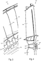
- FIG. 3 shows a perspective view of a second embodiment of the integrally bladed rotor 10.
- the joining zone 20 has in the region of adjacent blades 14 spacers, in each of which a discharge opening 28 is provided.
- the relief openings 28 serve on the one hand to relieve thermal and mechanical stresses in the edge region of the rotor base body 12 and on the other hand to reduce weight and material savings.
- overflow pipes 30 are embedded in the joining zone 20 in the metal powder 24.
- FIG. 4 shows a section through the in FIG. 3 shown rotor 10 at the level of a discharge opening 28.
- the joining zone 20 is substantially completely filled with metal powder 24 with the exception of the discharge opening 28.
- the rotor base body 12 is preferably a forged polycrystal of nickel-based alloys.
- the blades 14 may be made of nickel-base single crystals, directionally solidified materials, or polycrystalline materials, with the materials chosen according to the application needs of the rotor.
- the rotor base body 12 with a first welding surface 16 and at least one blade 14 with a second welding surface 18 are provided.
- the first welding surface 16, to which all blades 14 are welded, extends in particular rotationally symmetrical about the rotor base body 12. It is also possible that a plurality of separate first welding surfaces 16 are provided, wherein, for example, the number of first welding surfaces 16 on the rotor body 12 of the number to be attached blades 14 corresponds.
- Blade 14 and rotor base body 12 are positioned relative to each other so that a joining zone 20 is formed between the first and second welding surfaces 16, 18.
- the joining zone 20 extends rotationally symmetrical about the entire rotor body 12.
- a thin layer of metal powder 24 is introduced into the joining zone 20 and distributed over the entire joining zone 20 with the aid of the stripping rake 26 in a homogeneous thickness.
- the metal powder 24 is then welded by laser or electron beam, wherein the first welding surface 16 and the second welding surface 18 are joined by the welded metal powder 24.
- the energy input during welding can be chosen to be minimal, so that no macroscopic melting takes place at the second welding surface 18 of the blade 14 and the material properties of the blade 14 are preserved.
- a second layer of metal powder 24 is introduced into the joining zone 20 and rewelded. This process is repeated until the entire joining zone 20 is filled with metal powder 24.
- the first and second welding surfaces 16, 18 are tapered surfaces in the illustrated embodiment, thereby providing good accessibility to the metal powder 24 and the laser or electron beam.
- the welding surfaces 16, 18 may also have other geometries.
- FIG. 2 the rotor 10 is shown during the joining process, wherein the joining zone 20 is approximately half filled with metal powder 24. As can be clearly seen in this illustration, the metal powder layers run essentially in the rotor plane (radial plane).
- the manufacturing process is substantially analogous to the first embodiment.
- the joining zone 20 is in this case not rotationally symmetrical, but has widenings in the region of adjacent blades 14, in which at the beginning of the process in the positioning of the rotor base body 12 and blades 14 overflow pipes 30 are arranged to form relief openings 28.
- no metal powder 24 is welded, whereby the discharge opening 28 is released when filling the joining zone 20.
- the overflow pipes 30 form an overflow for excess metal powder 24. Is the joining zone 20, as in FIG. 4 shown, approximately filled, it is possible that excess metal powder 24 is filled in the joint zone 20. By the scrape-rake 26 this excess metal powder 24 is pushed into the relief opening 28 formed by the overflow pipe 30, falls through the discharge opening 28 and can be collected on the other side and reused.
- the welding process is consequently stirred in the lying state of the rotor.
- the rotor 10 after the joining process substantially corresponds to its desired final contour, whereby subsequent processing steps can be saved.
Landscapes
- Engineering & Computer Science (AREA)
- Mechanical Engineering (AREA)
- Physics & Mathematics (AREA)
- Optics & Photonics (AREA)
- Plasma & Fusion (AREA)
- Ceramic Engineering (AREA)
- General Engineering & Computer Science (AREA)
- Powder Metallurgy (AREA)
Description
- Die Erfindung betrifft ein Verfahren zum Herstellen eines integral beschaufelten Rotors, insbesondere für eine Gasturbine, sowie den Rotor selbst.
- Gasturbinenrotoren mit integraler Beschaufelung bezeichnet man abhängig davon, ob ein im Querschnitt scheibenförmiger oder ein im Querschnitt ringförmiger Rotor bzw. Rotorträger (im Folgenden Rotorgrundkörper genannt) vorhanden ist, als Blisk bzw. Bling. Blisk ist die Kurzform von Bladed Disk und Bling von Bladed Ring.
- Aus dem Stand der Technik ist es bekannt, Gasturbinenrotoren mit integraler Beschaufelung durch Fräsen aus dem Vollen herzustellen, was natürlich sehr aufwendig und teuer ist, weshalb dieses Verfahren nur für relativ kleine Gasturbinenrotoren Verwendung gefunden hat.
- Ein anderes, bei großen Rotoren Anwendung findendes Verfahren ist das Reibschweißen. Dabei werden Rotorgrundkörper und die Schaufeln separat hergestellt und anschließend miteinander reibverschweißt, insbesondere durch Linearreibschweißen. Ein Vorteil des Herstellens mittels Schweißen besteht darin, dass Rotorgrundkörper und Turbinenschaufeln aus unterschiedlichen Materialien gefertigt werden können, die den unterschiedlichen Anforderungen dieser Abschnitte des Rotors anpassbar sind. Schwierig ist die Ausrichtung der Schaufeln zum Rotorgrundkörper im gefügten Zustand, insbesondere beim Reibschweißen, bei dem eines der beiden Teile relativ zum anderen bewegt werden muss. Bei Reibschweißverfabren bildet sich im Allgemeinen ein Schweißwulst aus, der nach dem Schweißvorgang durch weitere Bearbeitung des Rotors, beispielsweise durch Fräsen, entfernt werden muss.
- Die Schaufeln des Rotors bestehen beispielsweise aus einkristallinen oder anderen Materialien, die ein Schmelzschweißverfahren nicht ermöglichen. Aus dem Stand der Technik ist es bekannt, zuerst ein Adapterelement an den Schaufelfuß zu fügen, welches dann wiederum an den Rotorgrundkörper angeschweißt wird.
- Weitere Beispiele für das Verbinden von Schaufeln mit Rotorscheiben bzw. allgemein das Verbinden von Bauteilen und insbesondere das Schweißen sind aus der
DE 10 2004 032 975 A1 ,WO 2005/075140 A1 ,US 4,096,615 A ,EP 2 000 631 A2 und derJP 62107866 A - Aufgabe der Erfindung ist es, ein Verfahren zum Herstellen eines integral beschaufelten Rotors zu schaffen, bei dem negative Auswirkungen auf die Materialeigenschaften durch die Fügevorgänge vermieden werden können und der Rotor nach dem Fügevorgang keine aufwendige Nachbearbeitung benötigt. Ferner soll ein möglichst einfach herstellbarer Rotor angegeben werden.
- Das erfindungsgemäße Verfahren sieht hierzu die folgenden Schritte vor. In einem ersten Schritt werden ein Rotorgrundkörper mit wenigstens einer ersten Schweißfläche und eine Schaufel mit einer zweiten Schweißfläche bereitgestellt. Im folgenden Schritt werden Rotorgrundkörper und Schaufel positioniert, sodass die Stirnseiten des Rotors die Schweißflächen begrenzen und zwischen erster und zweiter Schweißfläche eine Fügezone gebildet wird, die sich zwischen den Stirnseiten des Rotors erstreckt, wobei eine erste Stirnfläche des Rotors der in Strömungsrichtung vorderen Seite des Rotors entspricht und eine zweite Stirnfläche des Rotors der in Strömungsrichtung hinteren Seite des Rotors entspricht. In einem abschließenden Schritt erfolgt ein Auffüllen der Fügezone mit Metallpulver und Schweißen des Metallpulvers mittels Laser oder Elektronenstrahl. Dabei wird die Fügezone schichtweise mit Metallpulver aufgefüllt, wobei jede Schicht geschweißt wird. Dabei verlaufen die Schichten in einer Radialebene des Rotors.
- Da bei diesem Verfahren die Schaufel und der Rotorgrundkörper nicht relativ zueinander bewegt werden müssen können die Schaufeln sehr genau relativ zum Rotorgrundkörper positioniert werden. Durch das Auffüllen der Fügezone unter Verwendung eines generativen Verfahrens, wie z. B. des Laserauftragschweißverfahrens, wird teures Material eingespart, das konventionell zerspanend abgearbeitet werden müsste, beispielsweise durch Abfräsen von Schweißwulsten. Auf diese Weise können auch tiefe Fügezonen aufgefüllt und geschweißt werden. Ferner wird eine einfache Geometrie der Fügezone und eine Ausnutzung der Rotationssymmetrie des Rotors ermöglicht.
- Gemäß der bevorzugten Ausführungsform sind natürlich mehrere Schaufeln und mehrere zugeordnete zweite Schweißflächen vorgesehen.
- Vorzugsweise läuft die Fügezone konisch zu. Dies ermöglicht eine einfache Geometrie der Schweißflächen und eine gute Zugänglichkeit für Metallpulver und Laser bzw. Elektronenstrahl.
- Vorzugsweise ist der Energieeintrag beim Schweißen so gewählt, dass an der zweiten Schweißfläche der Schaufel keine mikroskopische Aufschmelzung stattfindet. Dies verhindert eine negative Beeinflussung des Fügevorgang auf die Materialeigenschaften der Schaufel.
- Gemäß einer weiteren Variante des Verfahrens wird beim Auffüllen der Fügezone eine Entlastungsöffnung freigelassen. Auf diese Weise entsteht eine Entlastungsöffriung bereits beim Fügevorgang und muss nicht später durch Bohren oder Fräsen hergestellt werden, wodurch Material und Kosten eingespart werden.
- Zur Ausbildung der Entlastungsöffnung kann ein Überlaufrohr in der Fügezone eingebettet werden. Dies ermöglicht einerseits eine genaue Positionierung der Entlastungsöffnung und begrenzt andererseits die Tiefe der Fügezone.
- Vorzugsweise wird beim Auffüllen der Fügezone ein Abstreif-Rechen oder Bürsten oder Walzen (je nach Geometrie) verwendet. So kann das Metallpulver auf einfache Weise in Schichten gleicher Höhe verteilt werden.
- Die Erfindung betrifft darüber hinaus einen integral beschaufelten Rotor mit einer Fügezone zwischen Rotorgrundkörper und Schaufeln, die sich zwischen den Stirnseiten des Rotors erstreckt, wobei eine erste Stirnfläche des Rotors der in Strömungsrichtung vorderen Seite des Rotors entspricht und eine zweite Stirnfläche des Rotors der in Strömungsrichtung hinteren Seite des Rotors entspricht, wobei die Fügezone mit geschweißtem Metallpulver aufgefüllt ist. Die Fügezone weist dabei Schichten auf, die in einer Radialebene des Rotors verlaufen.
- Weitere Merkmale und Vorteile der Erfindung ergeben sich aus der nachfolgenden Beschreibung und aus den nachfolgenden Zeichnungen, auf die Bezug genommen wird. In den Zeichnungen zeigen:
-
Figur 1 einen Rotorgrundkörper und eine Schaufel eines Rotors gemäß einer ersten Ausführungsform der Erfindung vor dem Fügevorgang; -
Figur 2 den Rotorgrundkörper und die Schaufel gemäßFigur 1 während des Fügevorgang; -
Figur 3 eine perspektivische Ansicht eines Rotors gemäß einer zweiten Ausführungsform der Erfindung; und -
Figur 4 einen Schnitt durch den Rotor gemäßFigur 3 . -
Figur 1 zeigt einen Schnitt durch eine erste Ausführungsform eines integral beschaufelten Rotors 10 mit einem Rotorgrundkörper 12 und einer Schaufel 14 der zahlreichen Schaufeln vor dem Fügevorgang, bei dem Rotorgrundkörper 12 und Schaufel 14 integral miteinander verbunden werden. Der Rotorgrundkörper 12 weist eine konisch zulaufende erste Schweißfläche 16 auf. Die Schaufel 14 weist eine konisch zulaufende zweite Schweißfläche 18 im Bereich des Schaufelfußes auf. - Rotorgrundkörper 12 und Schaufel 14 sind so zueinander positioniert, dass sich die erste Schweißfläche 16 und die zweite Schweißfläche 18 gegenüberliegen, wobei zwischen den Schweißfläche 16, 18 eine Fügezone 20 gebildet wird.
- Rotorgrundkörper 12 und Schaufel 14 berühren sich entlang einer Linie 22 am linken Rand der Schweißflächen 16, 18. Die linke Stirnfläche des Rotors 10 weist somit einen direkten Übergang vom Rotorgrundkörper 12 zur Schaufel 14 auf, während auf der rechten Stirnfläche des Rotors 10 die Fügezone 20 zwischen Rotorgrundkörper 12 und Schaufel 14 liegt.
- In der in
Figur 1 gezeigten Ausführungsform bildet die linke Stirnfläche des Rotors 10 die in Strömungsrichtung vordere Seite des Rotors 10. Es ist natürlich auch möglich, dass die Linie 22, in der sich Rotorgrundkörper 12 und Schaufel 14 berühren, auf der rechten Seite der Schweißflächen 16, 18 liegt und die hintere Stirnfläche des Rotors 10 den direkten Übergang zwischen Rotorgrundkörper 12 und Schaufel 14 aufweist. Darüber hinaus ist auch möglich, dass die Linie 22 im Wesentlichen in der Mitte der Schweißflächen 16, 18 liegt und die Schweißflächen 16, 18 in beiden Richtungen konisch zulaufen, wobei eine linke und eine rechte Fügezone gebildet wird. -
Figur 2 zeigt den Rotor 10 gemäßFigur 1 , wobei die Fügezone 20 zur Hälfte mit Metallpulver 24 aufgefüllt ist. Ein schematisch gezeigter Abstreif-Rechen 26 wird für das gleichmäßige Auffüllen der Fügezone 20 verwendet. Der Abstreif-Rechen 26 kann entsprechend der Geometrie des Rotors 10 rotieren und kann somit über die gesamte rotationssymmetrische Fügezone 20 streichen. -
Figur 3 zeigt eine perspektivische Ansicht einer zweiten Ausführungsform des integral beschaufelten Rotors 10. Die Fügezone 20 weist im Bereich benachbarter Schaufeln 14 Verbreiterungen auf, in denen jeweils eine Entlastungsöffnung 28 vorgesehen ist. Die Entlastungsöffnungen 28 dienen einerseits zur Entlastung von thermischen und mechanischen Spannungen im Randbereich des Rotorgrundkörpers 12 und andererseits zur Gewichtsreduktion und Materialeinsparung. Zur Ausbildung der Entlastungsöffnungen 28 sind Überlaufrohre 30 in der Fügezone 20 im Metallpulver 24 eingebettet. -
Figur 4 zeigt einen Schnitt durch den inFigur 3 gezeigten Rotor 10 auf Höhe einer Entlastungsöffnung 28. Die Fügezone 20 ist mit Ausnahme der Entlastungsöffnung 28 im Wesentlichen vollständig mit Metallpulver 24 aufgefüllt. - Der Rotorgrundkörper 12 ist vorzugsweise ein geschmiedeter Polykristall aus Nickel-Basis-Legierungen.
- Die Schaufeln 14 können aus Nickel-Basis-Einkristallen, gerichtet erstarrten Materialien oder polykristallinen Materialien gefertigt sein, wobei die Materialien je nach Anwendungsbedürfnissen des Rotors gewählt werden.
- Im Folgenden wird das Herstellungsverfahren des integral beschaufelten Rotors 10 beschrieben.
- In einem ersten Verfahrensschritt werden der Rotorgrundkörper 12 mit einer ersten Schweißfläche 16 und wenigstens eine Schaufel 14 mit einer zweiten Schweißfläche 18 bereitgestellt. Die erste Schweißfläche 16, an der alle Schaufeln 14 angeschweißt werden, erstreckt sich insbesondere rotationssymmetrisch um den Rotorgrundkörper 12. Es ist auch möglich, dass mehrere getrennte erste Schweißflächen 16 vorgesehen sind, wobei beispielsweise die Anzahl der ersten Schweißflächen 16 am Rotorgrundkörper 12 der Anzahl der anzufügenden Schaufeln 14 entspricht.
- Es können entweder eine einzige Schaufel 14 oder mehrere Schaufeln 14, insbesondere alle Schaufeln 14, gleichzeitig am Rotorgrundkörper 12 angeschweißt werden. Schaufel 14 und Rotorgrundkörper 12 werden so zueinander positioniert, dass sich zwischen erster und zweiter Schweißfläche 16, 18 eine Fügezone 20 bildet. In der in
Figur 1 gezeigten ersten Ausführungsform erstreckt sich die Fügezone 20 rotationssymmetrisch um den gesamten Rotorgrundkörper 12. - Im nächsten Verfahrensschritt wird eine dünne Schicht Metallpulver 24 in die Fügezone 20 eingefüllt und mithilfe des Abstreif-Rechens 26 in homogener Dicke über die gesamte Fügezone 20 verteilt. Das Metallpulver 24 wird dann mittels Laser oder Elektronenstrahl geschweißt, wobei die erste Schweißfläche 16 und die zweite Schweißfläche 18 durch das geschweißte Metallpulver 24 verbunden werden.
- Indem nur eine dünne Schicht Metallpulver 24 durch den Laser oder Elektronenstrahl geschweißt wird, kann der Energieeintrag beim Schweißen minimal gewählt werden, sodass an der zweiten Schweißfläche 18 der Schaufel 14 keine makroskopische Aufschmelzung stattfindet und die Materialeigenschaften der Schaufel 14 erhalten bleiben.
- Nach dem ersten Schweißvorgang wird eine zweite Schicht Metallpulver 24 in die Fügezone 20 eingebracht und erneut angeschweißt. Dieser Vorgang wird so lange wiederholt, bis die gesamte Fügezone 20 mit Metallpulver 24 aufgefüllt ist.
- Die erste und zweite Schweißfläche 16, 18 sind in der gezeigten Ausführungsform konisch zulaufende Flächen, wodurch eine gute Zugänglichkeit für das Metallpulver 24 und den Laser bzw. Elektronenstrahl erreicht wird. Die Schweißflächen 16, 18 können aber auch andere Geometrien aufweisen.
- In
Figur 2 ist der Rotor 10 während des Fügevorgangs gezeigt, wobei die Fügezone 20 ungefähr zur Hälfte mit Metallpulver 24 aufgefüllt ist. Wie man in dieser Darstellung gut erkennen kann, verlaufen die Metallpulverschichten im Wesentlichen in der Rotorebene (Radialebene). - In der in
Figur 3 und Figur 4 gezeigten zweiten Ausführungsform des Rotors 10 verläuft das Herstellungsverfahren im Wesentlichen analog zur ersten Ausführungsform. Die Fügezone 20 ist hierbei nicht rotationssymmetrisch ausgebildet, sondern weist Verbreiterungen im Bereich von benachbarten Schaufeln 14 auf, in denen zu Beginn des Verfahrens bei der Positionierung von Rotorgrundkörper 12 und Schaufeln 14 Überlaufrohre 30 zur Bildung von Entlastungsöffnungen 28 angeordnet werden. Im Inneren der Überlaufrohre 30 wird kein Metallpulver 24 geschweißt, wodurch beim Auffüllen der Fügezone 20 die Entlastungsöffnung 28 freigelassen wird. - Die Überlaufrohre 30 bilden einen Überlauf für überschüssiges Metallpulver 24. Ist die Fügezone 20, wie in
Figur 4 gezeigt, annähernd aufgefüllt, so ist es möglich, dass überschüssiges Metallpulver 24 in die Fügezone 20 gefüllt wird. Durch den Abstreif-Rechen 26 wird dieses überschüssige Metallpulver 24 in die durch das Überlaufrohr 30 gebildete Entlastungsöffnung 28 geschoben, fällt durch die Entlastungsöffnung 28 und kann auf der anderen Seite gesammelt und wieder verwendet werden. - Das Schweißverfahren wird folglich im liegenden Zustand des Rotors ausgerührt.
- Durch einen solchen generativen Fügevorgang entspricht der Rotor 10 nach dem Fügevorgang im Wesentlichen seiner gewünschten Endkontur, wodurch nachträgliche Bearbeitungsschritte eingespart werden können.
Claims (7)
- Verfahren zur Herstellung eines integral be schaufelten Rotors (10) mit einem Rotorgrundkörper und einer Vielzahl an Schaufeln, insbesondere für eine Gasturbine, mit den Verfahrensschritten:- Bereitstellen eines Rotorgrundkörpers (12) mit wenigstens einer ersten Schweißfläche (16) und einer Schaufel (14) mit einer zweiten Schweißfläche (18);- Positionierung von Rotorgrundkörper (12) und Schaufel (14), sodass die Stirnseiten des Rotors die Schweißflächen (16,18) begrenzen und zwischen erster und zweiter Schweißfläche (16,18) eine Fügezone (20) gebildet wird, die sich zwischen den Stirnseiten des Rotors erstreckt, wobei eine erste Stirnfläche des Rotors (10) der in Strömungsrichtung vorderen Seite des Rotors (10) entspricht und eine zweite Stirnfläche des Rotors (10) der in Strömungsrichtung hinteren Seite des Rotors (10) entspricht;- Auffüllen der Fügezone (20) mit Metallpulver (24) und Schweißen des Metallpulvers (24) mittels Laser oder Elektronenstrahl, wobei die Fügezone (20) schichtweise mit Metallpulver (24) aufgefüllt wird, wobei jede Schicht geschweißt wird und wobei die Schichten in einer Radialebene des Rotors verlaufen.
- Verfahren nach Anspruch 1, dadurch gekennzeichnet, dass die Fügezone (20) konisch zuläuft.
- Verfahren nach einem der vorhergehenden Ansprüche, dadurch gekennzeichnet, dass der Energieeintrag beim Schweißen so gewählt ist, dass an der zweiten Schweißfläche (18) der Schaufel (14) keine makroskopische Aufschmelzung stattfindet.
- Verfahren nach einem der vorhergehenden Ansprüche, dadurch gekennzeichnet, dass beim Auffüllen der Fügezone (20) eine Entlastungsöffnung (28) freigelassen wird.
- Verfahren nach Anspruch 6, dadurch gekennzeichnet, dass zur Ausbildung der Entlastungsöffnung (28) ein Überlaufrohr (30) in der Fügezone (20) eingebettet wird.
- Verfahren nach einem der vorhergehenden Ansprüche, dadurch gekennzeichnet, dass beim Auffüllen der Fügezone (20) ein Abstreif-Rechen (26), eine Abstreifbürste oder eine Walze verwendet wird.
- Integral beschaufelter Rotor (10), insbesondere für eine Gasturbine, mit einer Fügezone (20) zwischen Rotorgrundkörper (12) und Schaufeln (14), die sich zwischen den Stirnseiten des Rotors erstreckt, wobei eine erste Stirnfläche des Rotors (10) der in Strömungsrichtung vorderen Seite des Rotors (10) entspricht und eine zweite Stirnfläche des Rotors (10) der in Strömungsrichtung hinteren Seite des Rotors (10) entspricht, wobei die Fügezone (20) mit geschweißtem Metallpulver (24) aufgefüllt ist, und die Fügezone (20) Schichten aufweist, die in einer Radialebene des Rotors verlaufen.
Applications Claiming Priority (2)
| Application Number | Priority Date | Filing Date | Title |
|---|---|---|---|
| DE102009010025A DE102009010025B4 (de) | 2009-02-21 | 2009-02-21 | Verfahren zum Herstellen eines integral beschaufelten Rotors |
| PCT/DE2010/000100 WO2010094255A1 (de) | 2009-02-21 | 2010-01-30 | Verfahren zum herstellen eines integral beschaufelten rotors sowie rotor |
Publications (2)
| Publication Number | Publication Date |
|---|---|
| EP2399006A1 EP2399006A1 (de) | 2011-12-28 |
| EP2399006B1 true EP2399006B1 (de) | 2017-08-23 |
Family
ID=42111821
Family Applications (1)
| Application Number | Title | Priority Date | Filing Date |
|---|---|---|---|
| EP10708092.1A Not-in-force EP2399006B1 (de) | 2009-02-21 | 2010-01-30 | Verfahren zum herstellen eines integral beschaufelten rotors sowie rotor |
Country Status (4)
| Country | Link |
|---|---|
| US (1) | US8936442B2 (de) |
| EP (1) | EP2399006B1 (de) |
| DE (1) | DE102009010025B4 (de) |
| WO (1) | WO2010094255A1 (de) |
Families Citing this family (3)
| Publication number | Priority date | Publication date | Assignee | Title |
|---|---|---|---|---|
| DE102010034337A1 (de) * | 2010-08-14 | 2012-02-16 | Mtu Aero Engines Gmbh | Verfahren zum Verbinden einer Turbinenschaufel mit einer Turbinenscheibe oder einem Turbinenring |
| US20130259698A1 (en) * | 2012-03-28 | 2013-10-03 | General Electric Company | Method of Joining at Least Two Components, a Method for Rendering a Component Resistant to Eroision, and a Turbine Blade |
| US9551230B2 (en) * | 2015-02-13 | 2017-01-24 | United Technologies Corporation | Friction welding rotor blades to a rotor disk |
Family Cites Families (13)
| Publication number | Priority date | Publication date | Assignee | Title |
|---|---|---|---|---|
| US2778095A (en) * | 1952-01-03 | 1957-01-22 | Maschf Augsburg Nuernberg Ag | Method of welding turbine blades |
| US3003745A (en) * | 1957-10-31 | 1961-10-10 | Bendix Corp | Turbine wheel containment |
| US4096615A (en) | 1977-05-31 | 1978-06-27 | General Motors Corporation | Turbine rotor fabrication |
| JPS62107866A (ja) | 1985-11-05 | 1987-05-19 | Mitsubishi Heavy Ind Ltd | 狭間隙部材の溶接方法 |
| US5038014A (en) | 1989-02-08 | 1991-08-06 | General Electric Company | Fabrication of components by layered deposition |
| US6815636B2 (en) | 2003-04-09 | 2004-11-09 | 3D Systems, Inc. | Sintering using thermal image feedback |
| JP4551082B2 (ja) * | 2003-11-21 | 2010-09-22 | 三菱重工業株式会社 | 溶接方法 |
| DE102004006154A1 (de) | 2004-02-07 | 2005-08-25 | Mtu Aero Engines Gmbh | Verfahren zum Verbinden von Bauteilen |
| DE102004032975A1 (de) * | 2004-07-08 | 2006-02-09 | Mtu Aero Engines Gmbh | Verfahren zum Verbinden von Schaufelblättern mit Schaufelfüßen oder Rotorscheiben bei der Herstellung und/oder Reparatur von Gasturbinenschaufeln oder integral beschaufelten Gasturbinenrotoren |
| DE102004043746B4 (de) * | 2004-09-10 | 2008-09-25 | Mtu Aero Engines Gmbh | Verfahren zur Herstellung eines mit Hohlschaufeln integral beschaufelten Gasturbinenrotors |
| DE102005025348B4 (de) * | 2005-05-31 | 2007-08-02 | Trumpf Werkzeugmaschinen Gmbh + Co. Kg | Verfahren zur Herstellung eines Formkörpers sowie Sensoreinheit zu dessen Durchführung |
| US7887299B2 (en) | 2007-06-07 | 2011-02-15 | Honeywell International Inc. | Rotary body for turbo machinery with mistuned blades |
| JP5061836B2 (ja) * | 2007-10-10 | 2012-10-31 | 株式会社日立プラントテクノロジー | 羽根車の溶接方法及び羽根車 |
-
2009
- 2009-02-21 DE DE102009010025A patent/DE102009010025B4/de not_active Expired - Fee Related
-
2010
- 2010-01-30 WO PCT/DE2010/000100 patent/WO2010094255A1/de not_active Ceased
- 2010-01-30 US US12/998,977 patent/US8936442B2/en not_active Expired - Fee Related
- 2010-01-30 EP EP10708092.1A patent/EP2399006B1/de not_active Not-in-force
Non-Patent Citations (1)
| Title |
|---|
| None * |
Also Published As
| Publication number | Publication date |
|---|---|
| WO2010094255A1 (de) | 2010-08-26 |
| DE102009010025B4 (de) | 2011-06-22 |
| US20110255981A1 (en) | 2011-10-20 |
| US8936442B2 (en) | 2015-01-20 |
| DE102009010025A1 (de) | 2010-09-09 |
| EP2399006A1 (de) | 2011-12-28 |
Similar Documents
| Publication | Publication Date | Title |
|---|---|---|
| DE102010037690A1 (de) | Turbinenrotor-Fabrikation unter Anwendung des Kaltspritzens | |
| DE102007050142A1 (de) | Verfahren zur Herstellung einer Blisk oder eines Blings, damit hergestelltes Bauteil und Turbinenschaufel | |
| DE102013104222A1 (de) | Hybrides Schneidwerkzeug, Spantransportabschnitt sowie Verfahren zur Herstellung eines Schneidwerkzeugs | |
| DE102010036527A1 (de) | Verfahren zum Schließen einer Öffnung in einer Komponente | |
| EP3069803A1 (de) | Schaufel einer strömungsmaschine aus unterschiedlichen werkstoffen und verfahren zur herstellung derselben | |
| DE102015210744A1 (de) | Verfahren zum Fertigen einer Turbinenschaufel | |
| EP3170609A1 (de) | Verfahren zum herstellen eines beschaufelten rotors für eine strömungsmaschine ; entsprechender beschaufelter rotor | |
| DE102009010109A1 (de) | Herstellung einer Turbinenblisk mit einer Oxikations- bzw. Korrosionsschutzschicht | |
| EP3243580B1 (de) | Verfahren zur herstellung einer kantenabdeckung für ein schaufelbauteil eines flugtriebwerks oder einer gasturbine sowie kantenabdeckung für ein schaufelbauteil | |
| DE102006044555A1 (de) | Reparaturverfahren | |
| EP2851146A1 (de) | Verfahren zur Herstellung einer Turbinenschaufel und zugehörige Turbinenschaufel | |
| WO2011009431A1 (de) | Verfahren zum austauschen einer schaufel eines rotors mit integrierter beschaufelung und ein derartiger rotor | |
| EP3081669B1 (de) | Verfahren zur herstellung von gedeckelten laufrädern | |
| EP2399006B1 (de) | Verfahren zum herstellen eines integral beschaufelten rotors sowie rotor | |
| EP2168707A1 (de) | Verfahren zur Herstellung eines integral beschaufelten Rotors sowie Rotor | |
| DE102010034337A1 (de) | Verfahren zum Verbinden einer Turbinenschaufel mit einer Turbinenscheibe oder einem Turbinenring | |
| EP2476864A1 (de) | Schaufel-Scheiben-Einheit für eine Strömungsmaschine sowie Verfahren zur Herstellung | |
| EP2781622A1 (de) | Generatives Verfahren insbesondere zur Herstellung eines Überzugs, Vorrichtung zur Durchführung des Verfahrens, Überzug und ein Bauteilfertigungsverfahren sowie ein Bauteil | |
| EP3281728A1 (de) | Verfahren zur herstellung eines bauteils einer rotationsmaschine sowie bauteil hergestellt nach einem solchen verfahren | |
| DE102009052783A1 (de) | Verfahren zum Herstellen einer Blisk oder eines Blings für eine Strömungsmaschine | |
| DE10343760B4 (de) | Verfahren zur Herstellung oder Reparatur eines beschaufelten Rotors für eine Strömungsmaschine sowie dafür geeignete Schaufeln bzw. Ersatzschaufelabschnitte | |
| DE102009043184A1 (de) | Verfahren zur Reparatur eines integralen Rotors und integraler Rotor | |
| DE102010006907B4 (de) | Verfahren zum Herstellen eines Hohlbauteils für eine Gasturbine | |
| EP2860352A1 (de) | Rotor, zugehöriges Herstellungsverfahren und Laufschaufel | |
| EP3538315B1 (de) | Verfahren zur herstellung eines hohlraums in einer schaufelplattform ; entsprechender schaufel |
Legal Events
| Date | Code | Title | Description |
|---|---|---|---|
| PUAI | Public reference made under article 153(3) epc to a published international application that has entered the european phase |
Free format text: ORIGINAL CODE: 0009012 |
|
| 17P | Request for examination filed |
Effective date: 20110504 |
|
| AK | Designated contracting states |
Kind code of ref document: A1 Designated state(s): AT BE BG CH CY CZ DE DK EE ES FI FR GB GR HR HU IE IS IT LI LT LU LV MC MK MT NL NO PL PT RO SE SI SK SM TR |
|
| DAX | Request for extension of the european patent (deleted) | ||
| 17Q | First examination report despatched |
Effective date: 20120710 |
|
| RAP1 | Party data changed (applicant data changed or rights of an application transferred) |
Owner name: MTU AERO ENGINES AG |
|
| GRAP | Despatch of communication of intention to grant a patent |
Free format text: ORIGINAL CODE: EPIDOSNIGR1 |
|
| INTG | Intention to grant announced |
Effective date: 20170308 |
|
| GRAJ | Information related to disapproval of communication of intention to grant by the applicant or resumption of examination proceedings by the epo deleted |
Free format text: ORIGINAL CODE: EPIDOSDIGR1 |
|
| GRAS | Grant fee paid |
Free format text: ORIGINAL CODE: EPIDOSNIGR3 |
|
| GRAP | Despatch of communication of intention to grant a patent |
Free format text: ORIGINAL CODE: EPIDOSNIGR1 |
|
| INTC | Intention to grant announced (deleted) | ||
| GRAA | (expected) grant |
Free format text: ORIGINAL CODE: 0009210 |
|
| INTG | Intention to grant announced |
Effective date: 20170711 |
|
| AK | Designated contracting states |
Kind code of ref document: B1 Designated state(s): AT BE BG CH CY CZ DK EE ES FI FR GB GR HR HU IE IS IT LI LT LU LV MC MK MT NL NO PL PT RO SE SI SK SM TR |
|
| RBV | Designated contracting states (corrected) |
Designated state(s): AT BE BG CH CY CZ DK EE ES FI FR GB GR HR HU IE IS IT LI LT LU LV MC MK MT NL NO PL PT RO SE SI SK SM TR |
|
| REG | Reference to a national code |
Ref country code: DE Ref legal event code: R108 Ref country code: GB Ref legal event code: FG4D Free format text: NOT ENGLISH |
|
| REG | Reference to a national code |
Ref country code: CH Ref legal event code: EP |
|
| REG | Reference to a national code |
Ref country code: AT Ref legal event code: REF Ref document number: 921571 Country of ref document: AT Kind code of ref document: T Effective date: 20170915 |
|
| REG | Reference to a national code |
Ref country code: IE Ref legal event code: FG4D Free format text: LANGUAGE OF EP DOCUMENT: GERMAN |
|
| REG | Reference to a national code |
Ref country code: SE Ref legal event code: TRGR |
|
| REG | Reference to a national code |
Ref country code: NL Ref legal event code: MP Effective date: 20170823 |
|
| REG | Reference to a national code |
Ref country code: LT Ref legal event code: MG4D |
|
| REG | Reference to a national code |
Ref country code: FR Ref legal event code: PLFP Year of fee payment: 9 |
|
| PG25 | Lapsed in a contracting state [announced via postgrant information from national office to epo] |
Ref country code: NO Free format text: LAPSE BECAUSE OF FAILURE TO SUBMIT A TRANSLATION OF THE DESCRIPTION OR TO PAY THE FEE WITHIN THE PRESCRIBED TIME-LIMIT Effective date: 20171123 Ref country code: HR Free format text: LAPSE BECAUSE OF FAILURE TO SUBMIT A TRANSLATION OF THE DESCRIPTION OR TO PAY THE FEE WITHIN THE PRESCRIBED TIME-LIMIT Effective date: 20170823 Ref country code: FI Free format text: LAPSE BECAUSE OF FAILURE TO SUBMIT A TRANSLATION OF THE DESCRIPTION OR TO PAY THE FEE WITHIN THE PRESCRIBED TIME-LIMIT Effective date: 20170823 Ref country code: NL Free format text: LAPSE BECAUSE OF FAILURE TO SUBMIT A TRANSLATION OF THE DESCRIPTION OR TO PAY THE FEE WITHIN THE PRESCRIBED TIME-LIMIT Effective date: 20170823 Ref country code: LT Free format text: LAPSE BECAUSE OF FAILURE TO SUBMIT A TRANSLATION OF THE DESCRIPTION OR TO PAY THE FEE WITHIN THE PRESCRIBED TIME-LIMIT Effective date: 20170823 |
|
| PG25 | Lapsed in a contracting state [announced via postgrant information from national office to epo] |
Ref country code: PL Free format text: LAPSE BECAUSE OF FAILURE TO SUBMIT A TRANSLATION OF THE DESCRIPTION OR TO PAY THE FEE WITHIN THE PRESCRIBED TIME-LIMIT Effective date: 20170823 Ref country code: BG Free format text: LAPSE BECAUSE OF FAILURE TO SUBMIT A TRANSLATION OF THE DESCRIPTION OR TO PAY THE FEE WITHIN THE PRESCRIBED TIME-LIMIT Effective date: 20171123 Ref country code: ES Free format text: LAPSE BECAUSE OF FAILURE TO SUBMIT A TRANSLATION OF THE DESCRIPTION OR TO PAY THE FEE WITHIN THE PRESCRIBED TIME-LIMIT Effective date: 20170823 Ref country code: IS Free format text: LAPSE BECAUSE OF FAILURE TO SUBMIT A TRANSLATION OF THE DESCRIPTION OR TO PAY THE FEE WITHIN THE PRESCRIBED TIME-LIMIT Effective date: 20171223 Ref country code: LV Free format text: LAPSE BECAUSE OF FAILURE TO SUBMIT A TRANSLATION OF THE DESCRIPTION OR TO PAY THE FEE WITHIN THE PRESCRIBED TIME-LIMIT Effective date: 20170823 Ref country code: GR Free format text: LAPSE BECAUSE OF FAILURE TO SUBMIT A TRANSLATION OF THE DESCRIPTION OR TO PAY THE FEE WITHIN THE PRESCRIBED TIME-LIMIT Effective date: 20171124 |
|
| PG25 | Lapsed in a contracting state [announced via postgrant information from national office to epo] |
Ref country code: CZ Free format text: LAPSE BECAUSE OF FAILURE TO SUBMIT A TRANSLATION OF THE DESCRIPTION OR TO PAY THE FEE WITHIN THE PRESCRIBED TIME-LIMIT Effective date: 20170823 Ref country code: RO Free format text: LAPSE BECAUSE OF FAILURE TO SUBMIT A TRANSLATION OF THE DESCRIPTION OR TO PAY THE FEE WITHIN THE PRESCRIBED TIME-LIMIT Effective date: 20170823 Ref country code: DK Free format text: LAPSE BECAUSE OF FAILURE TO SUBMIT A TRANSLATION OF THE DESCRIPTION OR TO PAY THE FEE WITHIN THE PRESCRIBED TIME-LIMIT Effective date: 20170823 |
|
| PG25 | Lapsed in a contracting state [announced via postgrant information from national office to epo] |
Ref country code: SM Free format text: LAPSE BECAUSE OF FAILURE TO SUBMIT A TRANSLATION OF THE DESCRIPTION OR TO PAY THE FEE WITHIN THE PRESCRIBED TIME-LIMIT Effective date: 20170823 Ref country code: IT Free format text: LAPSE BECAUSE OF FAILURE TO SUBMIT A TRANSLATION OF THE DESCRIPTION OR TO PAY THE FEE WITHIN THE PRESCRIBED TIME-LIMIT Effective date: 20170823 Ref country code: SK Free format text: LAPSE BECAUSE OF FAILURE TO SUBMIT A TRANSLATION OF THE DESCRIPTION OR TO PAY THE FEE WITHIN THE PRESCRIBED TIME-LIMIT Effective date: 20170823 Ref country code: EE Free format text: LAPSE BECAUSE OF FAILURE TO SUBMIT A TRANSLATION OF THE DESCRIPTION OR TO PAY THE FEE WITHIN THE PRESCRIBED TIME-LIMIT Effective date: 20170823 |
|
| PLBE | No opposition filed within time limit |
Free format text: ORIGINAL CODE: 0009261 |
|
| STAA | Information on the status of an ep patent application or granted ep patent |
Free format text: STATUS: NO OPPOSITION FILED WITHIN TIME LIMIT |
|
| 26N | No opposition filed |
Effective date: 20180524 |
|
| PG25 | Lapsed in a contracting state [announced via postgrant information from national office to epo] |
Ref country code: SI Free format text: LAPSE BECAUSE OF FAILURE TO SUBMIT A TRANSLATION OF THE DESCRIPTION OR TO PAY THE FEE WITHIN THE PRESCRIBED TIME-LIMIT Effective date: 20170823 |
|
| REG | Reference to a national code |
Ref country code: CH Ref legal event code: PL |
|
| PG25 | Lapsed in a contracting state [announced via postgrant information from national office to epo] |
Ref country code: MT Free format text: LAPSE BECAUSE OF FAILURE TO SUBMIT A TRANSLATION OF THE DESCRIPTION OR TO PAY THE FEE WITHIN THE PRESCRIBED TIME-LIMIT Effective date: 20170823 |
|
| PG25 | Lapsed in a contracting state [announced via postgrant information from national office to epo] |
Ref country code: LU Free format text: LAPSE BECAUSE OF NON-PAYMENT OF DUE FEES Effective date: 20180130 |
|
| REG | Reference to a national code |
Ref country code: IE Ref legal event code: MM4A |
|
| REG | Reference to a national code |
Ref country code: BE Ref legal event code: MM Effective date: 20180131 |
|
| PG25 | Lapsed in a contracting state [announced via postgrant information from national office to epo] |
Ref country code: CH Free format text: LAPSE BECAUSE OF NON-PAYMENT OF DUE FEES Effective date: 20180131 Ref country code: LI Free format text: LAPSE BECAUSE OF NON-PAYMENT OF DUE FEES Effective date: 20180131 Ref country code: BE Free format text: LAPSE BECAUSE OF NON-PAYMENT OF DUE FEES Effective date: 20180131 |
|
| PG25 | Lapsed in a contracting state [announced via postgrant information from national office to epo] |
Ref country code: IE Free format text: LAPSE BECAUSE OF NON-PAYMENT OF DUE FEES Effective date: 20180130 |
|
| REG | Reference to a national code |
Ref country code: AT Ref legal event code: MM01 Ref document number: 921571 Country of ref document: AT Kind code of ref document: T Effective date: 20180130 |
|
| PG25 | Lapsed in a contracting state [announced via postgrant information from national office to epo] |
Ref country code: AT Free format text: LAPSE BECAUSE OF NON-PAYMENT OF DUE FEES Effective date: 20180130 |
|
| PG25 | Lapsed in a contracting state [announced via postgrant information from national office to epo] |
Ref country code: MC Free format text: LAPSE BECAUSE OF FAILURE TO SUBMIT A TRANSLATION OF THE DESCRIPTION OR TO PAY THE FEE WITHIN THE PRESCRIBED TIME-LIMIT Effective date: 20170823 |
|
| PG25 | Lapsed in a contracting state [announced via postgrant information from national office to epo] |
Ref country code: TR Free format text: LAPSE BECAUSE OF FAILURE TO SUBMIT A TRANSLATION OF THE DESCRIPTION OR TO PAY THE FEE WITHIN THE PRESCRIBED TIME-LIMIT Effective date: 20170823 |
|
| PGFP | Annual fee paid to national office [announced via postgrant information from national office to epo] |
Ref country code: SE Payment date: 20200127 Year of fee payment: 11 Ref country code: GB Payment date: 20200127 Year of fee payment: 11 |
|
| PG25 | Lapsed in a contracting state [announced via postgrant information from national office to epo] |
Ref country code: HU Free format text: LAPSE BECAUSE OF FAILURE TO SUBMIT A TRANSLATION OF THE DESCRIPTION OR TO PAY THE FEE WITHIN THE PRESCRIBED TIME-LIMIT; INVALID AB INITIO Effective date: 20100130 Ref country code: PT Free format text: LAPSE BECAUSE OF FAILURE TO SUBMIT A TRANSLATION OF THE DESCRIPTION OR TO PAY THE FEE WITHIN THE PRESCRIBED TIME-LIMIT Effective date: 20170823 |
|
| PG25 | Lapsed in a contracting state [announced via postgrant information from national office to epo] |
Ref country code: MK Free format text: LAPSE BECAUSE OF NON-PAYMENT OF DUE FEES Effective date: 20170823 Ref country code: CY Free format text: LAPSE BECAUSE OF FAILURE TO SUBMIT A TRANSLATION OF THE DESCRIPTION OR TO PAY THE FEE WITHIN THE PRESCRIBED TIME-LIMIT Effective date: 20170823 |
|
| PGFP | Annual fee paid to national office [announced via postgrant information from national office to epo] |
Ref country code: FR Payment date: 20200123 Year of fee payment: 11 |
|
| REG | Reference to a national code |
Ref country code: SE Ref legal event code: EUG |
|
| GBPC | Gb: european patent ceased through non-payment of renewal fee |
Effective date: 20210130 |
|
| PG25 | Lapsed in a contracting state [announced via postgrant information from national office to epo] |
Ref country code: FR Free format text: LAPSE BECAUSE OF NON-PAYMENT OF DUE FEES Effective date: 20210131 |
|
| PG25 | Lapsed in a contracting state [announced via postgrant information from national office to epo] |
Ref country code: SE Free format text: LAPSE BECAUSE OF NON-PAYMENT OF DUE FEES Effective date: 20210131 Ref country code: GB Free format text: LAPSE BECAUSE OF NON-PAYMENT OF DUE FEES Effective date: 20210130 |