EP2399019B1 - Séparateur d'eau, en particulier pour systèmes d'alimentation en carburant de moteurs à combustion interne dans des véhicules à moteur - Google Patents
Séparateur d'eau, en particulier pour systèmes d'alimentation en carburant de moteurs à combustion interne dans des véhicules à moteur Download PDFInfo
- Publication number
- EP2399019B1 EP2399019B1 EP10702267.5A EP10702267A EP2399019B1 EP 2399019 B1 EP2399019 B1 EP 2399019B1 EP 10702267 A EP10702267 A EP 10702267A EP 2399019 B1 EP2399019 B1 EP 2399019B1
- Authority
- EP
- European Patent Office
- Prior art keywords
- separating
- water separator
- separator according
- housing
- fuel
- Prior art date
- Legal status (The legal status is an assumption and is not a legal conclusion. Google has not performed a legal analysis and makes no representation as to the accuracy of the status listed.)
- Not-in-force
Links
Images
Classifications
-
- F—MECHANICAL ENGINEERING; LIGHTING; HEATING; WEAPONS; BLASTING
- F02—COMBUSTION ENGINES; HOT-GAS OR COMBUSTION-PRODUCT ENGINE PLANTS
- F02M—SUPPLYING COMBUSTION ENGINES IN GENERAL WITH COMBUSTIBLE MIXTURES OR CONSTITUENTS THEREOF
- F02M37/00—Apparatus or systems for feeding liquid fuel from storage containers to carburettors or fuel-injection apparatus; Arrangements for purifying liquid fuel specially adapted for, or arranged on, internal-combustion engines
- F02M37/22—Arrangements for purifying liquid fuel specially adapted for, or arranged on, internal-combustion engines, e.g. arrangements in the feeding system
- F02M37/24—Arrangements for purifying liquid fuel specially adapted for, or arranged on, internal-combustion engines, e.g. arrangements in the feeding system characterised by water separating means
-
- B—PERFORMING OPERATIONS; TRANSPORTING
- B01—PHYSICAL OR CHEMICAL PROCESSES OR APPARATUS IN GENERAL
- B01D—SEPARATION
- B01D17/00—Separation of liquids, not provided for elsewhere, e.g. by thermal diffusion
- B01D17/02—Separation of non-miscible liquids
- B01D17/04—Breaking emulsions
-
- B—PERFORMING OPERATIONS; TRANSPORTING
- B01—PHYSICAL OR CHEMICAL PROCESSES OR APPARATUS IN GENERAL
- B01D—SEPARATION
- B01D17/00—Separation of liquids, not provided for elsewhere, e.g. by thermal diffusion
- B01D17/02—Separation of non-miscible liquids
- B01D17/04—Breaking emulsions
- B01D17/045—Breaking emulsions with coalescers
-
- B—PERFORMING OPERATIONS; TRANSPORTING
- B01—PHYSICAL OR CHEMICAL PROCESSES OR APPARATUS IN GENERAL
- B01D—SEPARATION
- B01D29/00—Filters with filtering elements stationary during filtration, e.g. pressure or suction filters, not covered by groups B01D24/00 - B01D27/00; Filtering elements therefor
- B01D29/11—Filters with filtering elements stationary during filtration, e.g. pressure or suction filters, not covered by groups B01D24/00 - B01D27/00; Filtering elements therefor with bag, cage, hose, tube, sleeve or like filtering elements
- B01D29/13—Supported filter elements
- B01D29/23—Supported filter elements arranged for outward flow filtration
-
- B—PERFORMING OPERATIONS; TRANSPORTING
- B01—PHYSICAL OR CHEMICAL PROCESSES OR APPARATUS IN GENERAL
- B01D—SEPARATION
- B01D35/00—Filtering devices having features not specifically covered by groups B01D24/00 - B01D33/00, or for applications not specifically covered by groups B01D24/00 - B01D33/00; Auxiliary devices for filtration; Filter housing constructions
- B01D35/30—Filter housing constructions
-
- B—PERFORMING OPERATIONS; TRANSPORTING
- B01—PHYSICAL OR CHEMICAL PROCESSES OR APPARATUS IN GENERAL
- B01D—SEPARATION
- B01D36/00—Filter circuits or combinations of filters with other separating devices
- B01D36/003—Filters in combination with devices for the removal of liquids
-
- B—PERFORMING OPERATIONS; TRANSPORTING
- B01—PHYSICAL OR CHEMICAL PROCESSES OR APPARATUS IN GENERAL
- B01D—SEPARATION
- B01D2201/00—Details relating to filtering apparatus
- B01D2201/04—Supports for the filtering elements
- B01D2201/0415—Details of supporting structures
- B01D2201/0423—Details of supporting structures not in the inner side of the cylindrical filtering elements
Definitions
- the invention relates to a water separator, in particular for KraftstoffzuGermansysteme of internal combustion engines in motor vehicles of the type specified in the preamble of claim 1.
- a fuel filter which has in its housing a collecting space for the precipitated from the fuel water.
- the fuel is supplied from above into the filter housing, it being assumed that the heavier water components in the fuel sink down and enter the collecting space.
- part of the water emulsified in the fuel is carried with the fuel through the filter material, so that water is also present in the fuel on the output side of the filter.
- This fuel filter which is used in particular for diesel fuels of an internal combustion engine, comprises two filter stages, a first filter stage being provided for particle filtration.
- This filter stage consists of a hydrophilic filter material which has the property of finely divided water in the fuel to larger water particle elements to coalesce.
- a second filter stage is connected downstream of a hydrophobic material, wherein this second filter stage is located coaxially within the first filter stage. This arrangement is therefore chosen so that the fuel leaving the first filter stage and containing water fractions strikes the material of the last filter stage without deflection.
- a water separator according to the preamble of claim 1 is for example from the DE 20 2007 007 120 U1 known. Furthermore, the describes DE 10 2006 005 108 A1 a fuel filter with a ring filter insert and a separator arranged downstream of the ring filter insert, which has a separated by a chicane from a sedimentation chamber for separated water separation chamber.
- the present invention has for its object to provide a water separator of the generic type, which is simple in construction and with the efficient water separation is achieved. This object is achieved by a water separator with the features of claim 1.
- the housing By the design of the housing as a tubular body having a horizontal longitudinal axis and extending in the direction of the longitudinal axis Partition wall are formed in a simple manner, a deposition chamber and an underlying collecting space, wherein in the deposition chamber, the tubular element is arranged, which extends parallel to the partition wall.
- the housing has a transverse to the longitudinal direction of the division plane, are sealingly joined to the housing parts, wherein the dividing plane preferably is arranged adjacent to the inlet.
- the housing consists of only two parts that can be produced in a simple manner by an injection molding process.
- the housing parts may be made of metal or preferably of plastic.
- the location of the dividing plane near the inlet has the advantage that one of the housing parts at least approximately completely absorbs the separating element, whereas the other housing part merely represents a lid, which may optionally also have positioning means for fixing the position of the separator element.
- the partition wall extends from a rear end of the housing in the direction of a front end of the housing, wherein near the front end, a passage opening between the deposition chamber and collecting space is formed.
- the dividing wall extends up to the dividing plane.
- the inlet and the outlet are arranged in a same direction at opposite ends of the tubular body and coaxially with the tube element. In this way, only a small flow deflection is required on the total distance from inlet to drain.
- the tubular element may extend from the inlet to the outlet and be used as a component in the assembly of the water separator in the housing.
- the separation element expediently comprises two separation stages, wherein the first separation stage is coalescing and the second separation stage is hydrophobic.
- first coalescing separation stage water droplets are formed which, due to their gravitational force, sink downwards towards the dividing wall and are moved along the dividing wall in the direction of the opening for passage into the collecting chamber.
- the second separation stage of a hydrophobic material retains water portions still contained in the fuel or entrained water droplets, so that only fuel can pass through at the second separation stage.
- the second separation stage consists of a deposition fleece arranged downstream of the first separation stage and before the operation, which has a mesh size between 5 ⁇ m and 500 ⁇ m.
- a simple structure of the tubular element is achieved in that it comprises a supporting body, which on its lateral surface of a Abscheidemedium is surrounded, which covers the openings in the tubular element.
- the openings in the support body of the tubular element are preferably formed as longitudinal slots.
- the support body is received with an inlet end in a nozzle, which is formed in the housing and preferably extends coaxially to the inlet.
- a radial partition wall is arranged in the support body in the region of the outlet-side end of the separation medium of the first separation stage. As a result, a flow of the fuel is forced through the first separation stage.
- the tubular element has a pipe section adjoining the supporting body on the other side of the dividing wall, in which radial recesses are provided. Through these radial recesses, the fuel can enter the pipe section, wherein the pipe section is surrounded by a Abscheidevlies in the region of the recesses, which forms the second separation stage.
- an end of the tubular section adjacent to the drain is received in a neck formed in the housing, which preferably extends coaxially to the drain.
- the material of the first separation stage is a close-meshed screen, perforated plate or fabric.
- This material of the first separation stage can be surrounded in a simple manner by two mateable liquid-permeable half-shells and fastened by this to the support body.
- the half-shells have approximately the shape of a cylinder and thus determine the outer diameter of the tubular element, whereby only a small cross-sectional need exists in the housing.
- the half shells are preferably connected to one another by means of latching or clip connections, wherein the support element is clamped between the edges of the half shells. In this way, a fixation of the first Abscheidecut is given on the support element.
- the support element is designed with the partition wall and the pipe section as a one-piece plastic part. As a result, operations are saved in terms of production and assembly.
- a housing 2 is shown, which is designed substantially as a tubular body 3, which has a longitudinal direction LA and at ends 4, 5 is formed in each case approximately spherical segment-shaped.
- the housing 2 has a dividing plane TE transversely to the longitudinal direction LA, so that two housing parts 6, 7 form the tubular body 3 by joining on the dividing plane TE.
- the dividing plane TE is adjacent to a feed 8, so that the housing part 6 comprises approximately only the ball portion of the end 4, whereas the housing part 7 forms the main component of the tubular body 3.
- a nozzle 9 is arranged, which extends substantially coaxially to the inlet 8 and is formed integrally with the housing part 6.
- a extending in the longitudinal direction LA partition 10 is mounted, which extends slightly below the middle to the dividing plane TE.
- the partition wall 10 divided in this way the interior of the housing 2 in a separation chamber 11 and a plenum 12, wherein only in the region of the housing part 6, an opening 13 for connection between the deposition chamber 11 and collecting space 12 is given.
- a drain 14 for the fuel which runs in the same direction as the inlet 8 at the other end 4.
- a nozzle 15 is arranged, which extends at least approximately coaxially to the outlet 14.
- On the housing part 7 is at the end 5 below the drain 14 directly above a bottom 16 of the plenum 12, a water outlet 17 is arranged.
- the housing part 7 is preferably made in one piece as an injection molded part with the partition 10, the drain 14, the nozzle and the water outlet 17.
- the housing parts 6, 7 are preferably made of plastic and are welded in the region of the parting plane, whereby a tight connection is achieved, which is resistant to fuel.
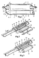
- Fig. 2 shows a separation element 18, which consists of several components, for better understanding, the components are shown partially in exploded view.
- the separating element 18 is designed as a tubular element 19, with a view to a horizontal arrangement in the in Fig. 1 shown deposition chamber 11 in the housing 2.
- Das Pipe element 19 comprises a support body 20, on which radial openings 21 are formed in the form of longitudinal slots.
- the support body 20 is surrounded over the length of the longitudinal slots by a separation medium 22, whereby a first separation stage A1 is formed.
- the separation medium 22, which is, for example, a close-meshed sieve, perforated plate or multilayer fabric, is fastened to the support body 20 by means of half-shells 23, 24 of a cylindrical shape.
- the half-shells 23, 24 consist of a thin-walled, formed into a half cylinder 25, perforated material and a frame 26 which extends over the edges of the half-cylinder 25. On the two frames 26 clips or notches may be provided to connect the two half-shells 23, 24 and thus cause an attachment to the support body 20.
- the production of the half-shells 23, 24 each of two separate parts, namely the half-cylinder 25 and the frame 26, offers the possibility of material combination of plastic and metal, but the half-shells can also be made of the same material.
- a transverse to the longitudinal direction of the partition wall 27 is arranged, which is located at a small distance to the rear in the flow direction S of the fuel end 21 of the openings.
- an element 31 is used for flow guidance, which is inserted so far into the support body 20 until it rests against the partition wall 27.
- the element 31 is designed that the flow cross-section is reduced within the support body 20 in the flow direction S. In this way, uniform loading of the first separation stage A1 over its entire length results.
- a pipe section 28 in which radial recesses 29 are provided.
- the pipe section 28 is surrounded by a Abscheidevlies 30, which spans the recesses 29.
- the Abscheidevlies 30 consists of a hydrophobic material and thus forms a second Abscheidecut A2.
- the mesh size of the Abscheidevlieses 30 may for example be between 5 microns and 500 microns.
- Fig. 3 is a variant to Fig. 2 shown with a separating element 18, which differs from that of the Fig. 2 differs in that the half-cylinder 25 and frame 26 of the half-shell 23 on the one hand and half-shell 24 on the other hand are integrally formed and thus also consist of the same material either of plastic or metal. All other features in Fig. 3 agree with those of Fig. 2 match, so that the same reference numerals are identical for the same parts.
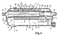
- the Fig. 4 shows a longitudinal section through a fully assembled water separator 1.
- the housing 2 consists of the housing part 6, 7, which form the tubular body 3, the interior of which through the longitudinal direction of the housing 2 extending partition 10 in the separation chamber 11 and the collecting space 12 is divided.
- the separation element 18 is in the form of a tubular element 19.
- the tubular element 19 comprises the support body 20 and the pipe section 28, which are arranged in alignment one behind the other.
- a sleeve 32 is formed, which is matched with respect to its outer periphery to the inner dimension of the nozzle 9 at the inlet 8 and received in this.
- the right end of the pipe section 28 is adapted to the inner dimension of the nozzle 15 at the outlet 14 and held therein.
- the assembly of the tubular element 19 in the housing 2 is possible in a simple manner by first the finished separation element 18 is inserted with its front end of the pipe section 28 in advance in the deposition chamber 11 and inserted into the socket 15. If necessary, measures for radial sealing between the nozzle 15 and the pipe section 28 are provided. Thereafter, the housing part 6 is fed in the direction of the housing part 7 and the nozzle 9 is inserted at the inlet 8 on the sleeve 32, wherein measures for radial sealing can also be taken. The housing part 6 is moved so far in the direction of the housing part 7 until a front edge 33 of the housing part 6 engages in a groove 34 of the housing part 7 and is sealingly connected thereto. Between the first separation stage A1 and the housing part 7 and the partition wall 20 remains an annular space which has a sufficient Flow ensured. All other reference numerals in Fig. 4 agree with those of the same parts Fig. 1 to 3 match.
- the fuel flows into the water separator 1 through the inlet 8 in the direction of the arrow S1 and passes through the sleeve 32 into the interior of the support body 20. Because of the partition wall 27, the fuel passes through the openings 21 designed as slots (see also FIG FIGS. 2 and 3 ) and further in the radial direction through the separation medium 22 and the half-shells 23, 24 in the annular space formed between the half-shells and the inner wall of the housing part 7 and the partition wall 10.
- the first separation stage A1 provides the element 31 for flow guidance in the interior of the support body 20.
Landscapes
- Chemical & Material Sciences (AREA)
- Engineering & Computer Science (AREA)
- Chemical Kinetics & Catalysis (AREA)
- Physics & Mathematics (AREA)
- Thermal Sciences (AREA)
- Combustion & Propulsion (AREA)
- Mechanical Engineering (AREA)
- General Engineering & Computer Science (AREA)
- Filtration Of Liquid (AREA)
- Fuel Cell (AREA)
Claims (15)
- Séparateur d'eau (1), notamment pour des systèmes d'alimentation en carburant de moteurs à combustion interne dans des véhicules automobiles, avec une chambre de séparation (11) réalisée dans un boîtier (2), un élément séparateur (18) placé à l'intérieur de cette chambre et un espace collecteur (12) disposé en dessous et destiné à collecter l'eau séparée du carburant, ainsi qu'avec une entrée (8) et une sortie (14) pour le carburant, le boîtier (2) étant essentiellement formé en tant que corps tubulaire (3) doté d'un axe longitudinal horizontal (LA), et l'élément séparateur (18) comprenant un élément tubulaire (19) disposé à l'horizontale dans la chambre de séparation (11) et pourvu d'ouvertures radiales (21) à travers lesquelles le carburant est acheminé, caractérisé en ce qu'une paroi de séparation (10), qui sépare la chambre de séparation (11) de l'espace collecteur (12), s'étend en direction de l'axe longitudinal (LA), l'élément tubulaire (19) évoluant, tout au moins approximativement, de manière parallèle à la paroi de séparation (10).
- Séparateur d'eau selon la revendication 1, caractérisé en ce que le boîtier (2) fait preuve d'un plan de séparation (TE) évoluant de manière transversale au sens longitudinal (LA) sur lequel des parties de boîtier (6, 7) sont assemblées de façon étanche, le plan de séparation (TE) étant de préférence moulé à proximité de l'entrée (8).
- Séparateur d'eau selon la revendication 1 ou 2, caractérisé en ce que la paroi de séparation (10) s'étend d'une extrémité arrière (5) du boîtier (2) vers une extrémité avant (4) du boîtier (2), une ouverture de passage (13) étant formée, à proximité de l'extrémité avant (4), entre la chambre de séparation (11) et l'espace collecteur (12).
- Séparateur d'eau selon les revendications 2 et 3, caractérisé en ce que la paroi de séparation (10) s'étend jusqu'au plan de séparation (TE).
- Séparateur d'eau selon l'une des revendications 1 à 4, caractérisé en ce que l'entrée (8) et la sortie (14) sont placées dans la même direction à des extrémités opposées (4, 5) du corps tubulaire (3) et de manière coaxiale par rapport à l'élément tubulaire (19).
- Séparateur d'eau selon l'une des revendications 1 à 5, caractérisé en ce que l'élément séparateur (18) comprend deux niveaux de séparation (A1, A2), le premier niveau de séparation (A1) étant coalescent et le deuxième niveau de séparation (A2) étant hydrophobe, le deuxième niveau de séparation (A2) notamment étant constitué d'un non-tissé de séparation (30) disposé en aval du premier niveau de séparation (A1) et en amont de la sortie (14) et doté de mailles d'une taille comprise entre 5 µm et 500 µm.
- Séparateur d'eau selon l'une des revendications 1 à 6, caractérisé en ce que l'élément tubulaire (19) comprend un élément d'appui (20) dont la surface est entourée d'un milieu de séparation (22) qui recouvre les ouvertures (21) de l'élément tubulaire (19), les ouvertures de l'élément d'appui (20) de l'élément tubulaire (19) étant notamment exécutées en tant que fentes longitudinales (21).
- Séparateur d'eau selon la revendication 7, caractérisé en ce qu'une extrémité côté entrée (32) de l'élément d'appui (20) est logée dans une tubulure (9) qui est formée dans le boîtier (2) et qui s'étend de préférence de manière coaxiale par rapport à l'entrée (8).
- Séparateur d'eau selon l'une des revendications 7 ou 8, caractérisé en ce qu'une paroi de séparation radiale (27) est placée dans l'élément d'appui (20) à proximité de l'extrémité côté sortie du milieu de séparation (22) du premier niveau de séparation (A1).
- Séparateur d'eau selon la revendication 9, caractérisé en ce que l'élément tubulaire (19) présente une section de tube (28) raccordée à l'élément d'appui (20) de l'autre côté de la paroi de séparation (27) et dans laquelle sont prévus des évidements radiaux (29).
- Séparateur d'eau selon les revendications 6 et 10, caractérisé en ce que la section de tube (28) est entourée du non-tissé de séparation (30) à proximité des évidements (29).
- Séparateur d'eau selon la revendication 10 ou 11, caractérisé en ce qu'une extrémité de la section de tube (28) voisine à la sortie (14) est logée dans une tubulure (15) formée dans le boîtier (2) et s'étendant de préférence de manière coaxiale par rapport à la sortie (14).
- Séparateur d'eau selon l'une des revendications 6 à 12, caractérisé en ce que le matériau du premier niveau de séparation (A1) est un tamis à mailles serrées, une tôle perforée ou un tissu.
- Séparateur d'eau selon l'une des revendications 7 à 13, caractérisé en ce qu'un élément (31) servant à guider le flux et réduisant dans le sens du flux (S) la section de flux au sein de l'élément d'appui (20) est disposé dans l'élément d'appui (20).
- Séparateur d'eau selon l'une des revendications 1 à 14, caractérisé en ce qu'une tubulure d'écoulement d'eau (17) est placée à l'extrémité (5) du boîtier (2) à laquelle se trouve la sortie (14) pour le carburant, directement au-dessus d'un fond (16) de l'espace collecteur (12).
Applications Claiming Priority (2)
| Application Number | Priority Date | Filing Date | Title |
|---|---|---|---|
| DE202009002303U DE202009002303U1 (de) | 2009-02-18 | 2009-02-18 | Wasserabscheider, insbesondere für Kraftstoffzuführsysteme von Brennkraftmaschinen in Kraftfahrzeugen |
| PCT/EP2010/050625 WO2010094529A1 (fr) | 2009-02-18 | 2010-01-20 | Séparateur d'eau, en particulier pour systèmes d'alimentation en carburant de moteurs à combustion interne dans des véhicules à moteur |
Publications (2)
| Publication Number | Publication Date |
|---|---|
| EP2399019A1 EP2399019A1 (fr) | 2011-12-28 |
| EP2399019B1 true EP2399019B1 (fr) | 2013-04-17 |
Family
ID=42041651
Family Applications (1)
| Application Number | Title | Priority Date | Filing Date |
|---|---|---|---|
| EP10702267.5A Not-in-force EP2399019B1 (fr) | 2009-02-18 | 2010-01-20 | Séparateur d'eau, en particulier pour systèmes d'alimentation en carburant de moteurs à combustion interne dans des véhicules à moteur |
Country Status (6)
| Country | Link |
|---|---|
| US (1) | US9194343B2 (fr) |
| EP (1) | EP2399019B1 (fr) |
| KR (1) | KR101667072B1 (fr) |
| CN (1) | CN102325986B (fr) |
| DE (1) | DE202009002303U1 (fr) |
| WO (1) | WO2010094529A1 (fr) |
Cited By (3)
| Publication number | Priority date | Publication date | Assignee | Title |
|---|---|---|---|---|
| DE102015215777A1 (de) | 2015-08-19 | 2017-02-23 | Mahle International Gmbh | Wasserabscheider |
| US11352991B2 (en) | 2017-09-15 | 2022-06-07 | Ufi Filters S.P.A. | Water separation group |
| US11565204B2 (en) | 2017-09-15 | 2023-01-31 | Ufi Filters S.P.A. | Water separation unit |
Families Citing this family (15)
| Publication number | Priority date | Publication date | Assignee | Title |
|---|---|---|---|---|
| DE202009002303U1 (de) * | 2009-02-18 | 2010-07-15 | Mann+Hummel Gmbh | Wasserabscheider, insbesondere für Kraftstoffzuführsysteme von Brennkraftmaschinen in Kraftfahrzeugen |
| US10561968B2 (en) * | 2013-03-13 | 2020-02-18 | Illinois Tool Works Inc. | Water separation filter |
| DE102015003101A1 (de) * | 2015-03-11 | 2016-09-15 | Mann + Hummel Gmbh | Filterelement |
| JP6380364B2 (ja) * | 2015-12-17 | 2018-08-29 | 株式会社デンソー | 燃料ポンプ及び燃料ポンプモジュール |
| DE102016010778A1 (de) | 2016-09-08 | 2018-03-08 | Mann+Hummel Gmbh | Trennmodul, Wasserabscheidevorrichtung mit einem Trennmodul und Filtersystem mit einer Wasserabscheidevorrichtung |
| DE102016222778A1 (de) * | 2016-11-18 | 2018-05-24 | Siemens Aktiengesellschaft | Verfahren zum Entwässern eines Betriebsstoffs, Entwässerungseinrichtung sowie Betriebsstoff-Versorgungseinrichtung |
| DE102017001380A1 (de) * | 2017-02-14 | 2018-08-16 | Mann+Hummel Gmbh | Kraftstofffilter, Reinigungskartusche und Verwendung |
| GB2560721B (en) * | 2017-03-21 | 2021-01-06 | Bamford Excavators Ltd | An oil filter assembly |
| CN109989862B (zh) * | 2017-12-28 | 2022-05-27 | 上海欧菲滤清器有限公司 | 水分离模块以及燃油过滤分离组件及其组装方法 |
| CN110608117B (zh) * | 2018-06-15 | 2026-04-03 | 上海欧菲滤清器有限公司 | 水分离组 |
| DE102019121342B4 (de) * | 2018-08-15 | 2021-03-18 | Mann+Hummel Gmbh | Filterelement für den Einsatz als Partikelfilter in einem Kühlkreislauf eines elektrochemischen Energiewandlers und Verwendung des Filterelements in einer Anordnung mit einem elektrochemischen Energiewandler und einem Kühlkreislauf |
| RU193731U1 (ru) * | 2019-08-20 | 2019-11-12 | Акционерное общество "Рузаевский завод химического машиностроения" (АО "Рузхиммаш") | Нефтегазовый сепаратор |
| KR102178858B1 (ko) * | 2019-09-25 | 2020-11-13 | 주식회사 코아비스 | 연료펌프용 스트레이너 |
| KR102889287B1 (ko) * | 2023-09-26 | 2025-11-24 | 주식회사 투엔 | 미세수분 제거 장치 |
| WO2025071219A1 (fr) * | 2023-09-26 | 2025-04-03 | 주식회사 투엔 | Appareil d'élimination de micro-humidité |
Family Cites Families (11)
| Publication number | Priority date | Publication date | Assignee | Title |
|---|---|---|---|---|
| DE2918216A1 (de) * | 1978-05-08 | 1979-12-13 | Fram Europ | Verfahren und vorrichtung zum trennen |
| US4740299A (en) | 1985-05-14 | 1988-04-26 | Parker Hannifin Corporation | Filter assembly with threaded collection bowl |
| US5480547A (en) * | 1994-03-08 | 1996-01-02 | Pall Corporation | Corrosive liquid coalescer |
| DE10123190A1 (de) | 2001-05-12 | 2002-11-14 | Mahle Filtersysteme Gmbh | Kraftstofffilter mit wasserabscheidenden Mitteln |
| CN2596054Y (zh) * | 2002-06-12 | 2003-12-31 | 王国利 | 机动车燃油滤水器 |
| DE10333185A1 (de) | 2003-07-22 | 2005-02-24 | Robert Bosch Gmbh | Flacher Kraftstofffilter |
| DE102006005108B4 (de) * | 2006-02-04 | 2017-10-12 | Mahle International Gmbh | Zylindrische Filtereinrichtung |
| ITRE20060113A1 (it) * | 2006-09-28 | 2008-03-29 | Ufi Filters Spa | Gruppo filtrante per carburante |
| DE202007007120U1 (de) * | 2007-05-16 | 2008-10-23 | Mann + Hummel Gmbh | Kraftstoffzuführeinrichtung, insbesondere für eine Brennkraftmaschine |
| DE102009009420A1 (de) * | 2009-02-18 | 2010-09-09 | Mann + Hummel Gmbh | Wasserabscheider insbesondere für Kraftstoffzuführsysteme von Brennkraftmaschinen in Kraftfahrzeugen |
| DE202009002303U1 (de) * | 2009-02-18 | 2010-07-15 | Mann+Hummel Gmbh | Wasserabscheider, insbesondere für Kraftstoffzuführsysteme von Brennkraftmaschinen in Kraftfahrzeugen |
-
2009
- 2009-02-18 DE DE202009002303U patent/DE202009002303U1/de not_active Expired - Lifetime
-
2010
- 2010-01-20 WO PCT/EP2010/050625 patent/WO2010094529A1/fr not_active Ceased
- 2010-01-20 KR KR1020117019706A patent/KR101667072B1/ko active Active
- 2010-01-20 US US13/202,188 patent/US9194343B2/en active Active
- 2010-01-20 CN CN201080008803.1A patent/CN102325986B/zh not_active Expired - Fee Related
- 2010-01-20 EP EP10702267.5A patent/EP2399019B1/fr not_active Not-in-force
Cited By (3)
| Publication number | Priority date | Publication date | Assignee | Title |
|---|---|---|---|---|
| DE102015215777A1 (de) | 2015-08-19 | 2017-02-23 | Mahle International Gmbh | Wasserabscheider |
| US11352991B2 (en) | 2017-09-15 | 2022-06-07 | Ufi Filters S.P.A. | Water separation group |
| US11565204B2 (en) | 2017-09-15 | 2023-01-31 | Ufi Filters S.P.A. | Water separation unit |
Also Published As
| Publication number | Publication date |
|---|---|
| KR101667072B1 (ko) | 2016-10-17 |
| DE202009002303U1 (de) | 2010-07-15 |
| CN102325986B (zh) | 2014-06-11 |
| US20120043267A1 (en) | 2012-02-23 |
| KR20110120295A (ko) | 2011-11-03 |
| US9194343B2 (en) | 2015-11-24 |
| WO2010094529A1 (fr) | 2010-08-26 |
| CN102325986A (zh) | 2012-01-18 |
| EP2399019A1 (fr) | 2011-12-28 |
Similar Documents
| Publication | Publication Date | Title |
|---|---|---|
| EP2399019B1 (fr) | Séparateur d'eau, en particulier pour systèmes d'alimentation en carburant de moteurs à combustion interne dans des véhicules à moteur | |
| EP2226107B1 (fr) | Séparateur d'eau, notamment pour systèmes d'entrée de carburant de moteurs à combustion interne dans des véhicules automobiles | |
| EP2145099B1 (fr) | Dispositif d'amenée de carburant destiné en particulier à un moteur à combustion interne | |
| DE69003407T2 (de) | Integriertes abgestimmtes Einlassystem. | |
| EP2935812B1 (fr) | Dispositif de séparation pour écoulement d'aérosol | |
| DE4216255A1 (de) | Ansaugrohr und Verfahren zu dessen Herstellung | |
| WO2007147598A1 (fr) | Filtre doté d'un insert remplaçable | |
| EP1222010A2 (fr) | Filtre pour liquide, notamment filtre a huile | |
| EP0777046A1 (fr) | Filtre pour carburants, spécialement adapté pour moteurs diesel | |
| DE19907264C1 (de) | Luftansaug-Schalldämpfer mit Wasserabscheider | |
| DE10212407B4 (de) | Tankinternes Kraftstoffpumpensystem | |
| EP3787769B1 (fr) | Élément filtrant à carburant et dispositif filtrant | |
| WO2015075055A1 (fr) | Insert de filtration pour dispositif de filtration | |
| DE102010030987B4 (de) | Fluidfilter | |
| EP2714231B1 (fr) | Filtre a huile d'une boite de vitesses pour vehicules automobiles | |
| DE10063283A1 (de) | Siebfilter für Fluidleitungen, insbesondere für hydraulische Druckleitungen in Brennkraftmaschinen | |
| DE202007003292U1 (de) | Ölabscheider mit mindestens einem Zyklon | |
| DE102010062595B4 (de) | Filtereinrichtung | |
| EP0655269A2 (fr) | Filtre pour carburants liquides | |
| DE20102217U1 (de) | Filter für Flüssigkeiten, insbesondere Kraftstoffe | |
| DE3133343C2 (fr) | ||
| DE102011056352B4 (de) | Kraftstofffilter | |
| DE19716175A1 (de) | Gehäusetopf zur Aufnahme einer Flüssigkeitsförderpumpe | |
| DE19634717A1 (de) | Filtereinrichtung für eine Kraftstoffördereinheit | |
| DE102018003414A1 (de) | Filtereinrichtung, insbesondere Luftfilter, und Verfahren zur Wartung einer Filtereinrichtung sowie deren Verwendung |
Legal Events
| Date | Code | Title | Description |
|---|---|---|---|
| PUAI | Public reference made under article 153(3) epc to a published international application that has entered the european phase |
Free format text: ORIGINAL CODE: 0009012 |
|
| 17P | Request for examination filed |
Effective date: 20110802 |
|
| AK | Designated contracting states |
Kind code of ref document: A1 Designated state(s): AT BE BG CH CY CZ DE DK EE ES FI FR GB GR HR HU IE IS IT LI LT LU LV MC MK MT NL NO PL PT RO SE SI SK SM TR |
|
| DAX | Request for extension of the european patent (deleted) | ||
| GRAP | Despatch of communication of intention to grant a patent |
Free format text: ORIGINAL CODE: EPIDOSNIGR1 |
|
| GRAS | Grant fee paid |
Free format text: ORIGINAL CODE: EPIDOSNIGR3 |
|
| GRAA | (expected) grant |
Free format text: ORIGINAL CODE: 0009210 |
|
| AK | Designated contracting states |
Kind code of ref document: B1 Designated state(s): AT BE BG CH CY CZ DE DK EE ES FI FR GB GR HR HU IE IS IT LI LT LU LV MC MK MT NL NO PL PT RO SE SI SK SM TR |
|
| REG | Reference to a national code |
Ref country code: GB Ref legal event code: FG4D Free format text: NOT ENGLISH |
|
| REG | Reference to a national code |
Ref country code: CH Ref legal event code: EP |
|
| REG | Reference to a national code |
Ref country code: IE Ref legal event code: FG4D Free format text: LANGUAGE OF EP DOCUMENT: GERMAN |
|
| REG | Reference to a national code |
Ref country code: AT Ref legal event code: REF Ref document number: 607451 Country of ref document: AT Kind code of ref document: T Effective date: 20130515 |
|
| REG | Reference to a national code |
Ref country code: DE Ref legal event code: R096 Ref document number: 502010002972 Country of ref document: DE Effective date: 20130613 |
|
| REG | Reference to a national code |
Ref country code: LT Ref legal event code: MG4D |
|
| REG | Reference to a national code |
Ref country code: NL Ref legal event code: VDEP Effective date: 20130417 |
|
| PG25 | Lapsed in a contracting state [announced via postgrant information from national office to epo] |
Ref country code: SI Free format text: LAPSE BECAUSE OF FAILURE TO SUBMIT A TRANSLATION OF THE DESCRIPTION OR TO PAY THE FEE WITHIN THE PRESCRIBED TIME-LIMIT Effective date: 20130417 Ref country code: LT Free format text: LAPSE BECAUSE OF FAILURE TO SUBMIT A TRANSLATION OF THE DESCRIPTION OR TO PAY THE FEE WITHIN THE PRESCRIBED TIME-LIMIT Effective date: 20130417 Ref country code: FI Free format text: LAPSE BECAUSE OF FAILURE TO SUBMIT A TRANSLATION OF THE DESCRIPTION OR TO PAY THE FEE WITHIN THE PRESCRIBED TIME-LIMIT Effective date: 20130417 Ref country code: IS Free format text: LAPSE BECAUSE OF FAILURE TO SUBMIT A TRANSLATION OF THE DESCRIPTION OR TO PAY THE FEE WITHIN THE PRESCRIBED TIME-LIMIT Effective date: 20130817 Ref country code: ES Free format text: LAPSE BECAUSE OF FAILURE TO SUBMIT A TRANSLATION OF THE DESCRIPTION OR TO PAY THE FEE WITHIN THE PRESCRIBED TIME-LIMIT Effective date: 20130728 Ref country code: SE Free format text: LAPSE BECAUSE OF FAILURE TO SUBMIT A TRANSLATION OF THE DESCRIPTION OR TO PAY THE FEE WITHIN THE PRESCRIBED TIME-LIMIT Effective date: 20130417 Ref country code: PT Free format text: LAPSE BECAUSE OF FAILURE TO SUBMIT A TRANSLATION OF THE DESCRIPTION OR TO PAY THE FEE WITHIN THE PRESCRIBED TIME-LIMIT Effective date: 20130819 Ref country code: NO Free format text: LAPSE BECAUSE OF FAILURE TO SUBMIT A TRANSLATION OF THE DESCRIPTION OR TO PAY THE FEE WITHIN THE PRESCRIBED TIME-LIMIT Effective date: 20130717 Ref country code: GR Free format text: LAPSE BECAUSE OF FAILURE TO SUBMIT A TRANSLATION OF THE DESCRIPTION OR TO PAY THE FEE WITHIN THE PRESCRIBED TIME-LIMIT Effective date: 20130718 |
|
| PG25 | Lapsed in a contracting state [announced via postgrant information from national office to epo] |
Ref country code: HR Free format text: LAPSE BECAUSE OF FAILURE TO SUBMIT A TRANSLATION OF THE DESCRIPTION OR TO PAY THE FEE WITHIN THE PRESCRIBED TIME-LIMIT Effective date: 20130417 Ref country code: LV Free format text: LAPSE BECAUSE OF FAILURE TO SUBMIT A TRANSLATION OF THE DESCRIPTION OR TO PAY THE FEE WITHIN THE PRESCRIBED TIME-LIMIT Effective date: 20130417 Ref country code: BG Free format text: LAPSE BECAUSE OF FAILURE TO SUBMIT A TRANSLATION OF THE DESCRIPTION OR TO PAY THE FEE WITHIN THE PRESCRIBED TIME-LIMIT Effective date: 20130717 Ref country code: CY Free format text: LAPSE BECAUSE OF FAILURE TO SUBMIT A TRANSLATION OF THE DESCRIPTION OR TO PAY THE FEE WITHIN THE PRESCRIBED TIME-LIMIT Effective date: 20130417 Ref country code: PL Free format text: LAPSE BECAUSE OF FAILURE TO SUBMIT A TRANSLATION OF THE DESCRIPTION OR TO PAY THE FEE WITHIN THE PRESCRIBED TIME-LIMIT Effective date: 20130417 |
|
| PG25 | Lapsed in a contracting state [announced via postgrant information from national office to epo] |
Ref country code: DK Free format text: LAPSE BECAUSE OF FAILURE TO SUBMIT A TRANSLATION OF THE DESCRIPTION OR TO PAY THE FEE WITHIN THE PRESCRIBED TIME-LIMIT Effective date: 20130417 Ref country code: SK Free format text: LAPSE BECAUSE OF FAILURE TO SUBMIT A TRANSLATION OF THE DESCRIPTION OR TO PAY THE FEE WITHIN THE PRESCRIBED TIME-LIMIT Effective date: 20130417 Ref country code: EE Free format text: LAPSE BECAUSE OF FAILURE TO SUBMIT A TRANSLATION OF THE DESCRIPTION OR TO PAY THE FEE WITHIN THE PRESCRIBED TIME-LIMIT Effective date: 20130417 Ref country code: CZ Free format text: LAPSE BECAUSE OF FAILURE TO SUBMIT A TRANSLATION OF THE DESCRIPTION OR TO PAY THE FEE WITHIN THE PRESCRIBED TIME-LIMIT Effective date: 20130417 |
|
| PLBE | No opposition filed within time limit |
Free format text: ORIGINAL CODE: 0009261 |
|
| STAA | Information on the status of an ep patent application or granted ep patent |
Free format text: STATUS: NO OPPOSITION FILED WITHIN TIME LIMIT |
|
| PG25 | Lapsed in a contracting state [announced via postgrant information from national office to epo] |
Ref country code: RO Free format text: LAPSE BECAUSE OF FAILURE TO SUBMIT A TRANSLATION OF THE DESCRIPTION OR TO PAY THE FEE WITHIN THE PRESCRIBED TIME-LIMIT Effective date: 20130417 Ref country code: NL Free format text: LAPSE BECAUSE OF FAILURE TO SUBMIT A TRANSLATION OF THE DESCRIPTION OR TO PAY THE FEE WITHIN THE PRESCRIBED TIME-LIMIT Effective date: 20130417 Ref country code: IT Free format text: LAPSE BECAUSE OF FAILURE TO SUBMIT A TRANSLATION OF THE DESCRIPTION OR TO PAY THE FEE WITHIN THE PRESCRIBED TIME-LIMIT Effective date: 20130417 |
|
| 26N | No opposition filed |
Effective date: 20140120 |
|
| REG | Reference to a national code |
Ref country code: DE Ref legal event code: R097 Ref document number: 502010002972 Country of ref document: DE Effective date: 20140120 |
|
| BERE | Be: lapsed |
Owner name: MANN+HUMMEL G.M.B.H. Effective date: 20140131 |
|
| PG25 | Lapsed in a contracting state [announced via postgrant information from national office to epo] |
Ref country code: LU Free format text: LAPSE BECAUSE OF FAILURE TO SUBMIT A TRANSLATION OF THE DESCRIPTION OR TO PAY THE FEE WITHIN THE PRESCRIBED TIME-LIMIT Effective date: 20140120 |
|
| REG | Reference to a national code |
Ref country code: CH Ref legal event code: PL |
|
| GBPC | Gb: european patent ceased through non-payment of renewal fee |
Effective date: 20140120 |
|
| PG25 | Lapsed in a contracting state [announced via postgrant information from national office to epo] |
Ref country code: LI Free format text: LAPSE BECAUSE OF NON-PAYMENT OF DUE FEES Effective date: 20140131 Ref country code: CH Free format text: LAPSE BECAUSE OF NON-PAYMENT OF DUE FEES Effective date: 20140131 |
|
| REG | Reference to a national code |
Ref country code: FR Ref legal event code: ST Effective date: 20140930 |
|
| REG | Reference to a national code |
Ref country code: IE Ref legal event code: MM4A |
|
| PG25 | Lapsed in a contracting state [announced via postgrant information from national office to epo] |
Ref country code: GB Free format text: LAPSE BECAUSE OF NON-PAYMENT OF DUE FEES Effective date: 20140120 Ref country code: FR Free format text: LAPSE BECAUSE OF NON-PAYMENT OF DUE FEES Effective date: 20140131 |
|
| PG25 | Lapsed in a contracting state [announced via postgrant information from national office to epo] |
Ref country code: BE Free format text: LAPSE BECAUSE OF NON-PAYMENT OF DUE FEES Effective date: 20140131 Ref country code: IE Free format text: LAPSE BECAUSE OF NON-PAYMENT OF DUE FEES Effective date: 20140120 |
|
| PG25 | Lapsed in a contracting state [announced via postgrant information from national office to epo] |
Ref country code: MC Free format text: LAPSE BECAUSE OF FAILURE TO SUBMIT A TRANSLATION OF THE DESCRIPTION OR TO PAY THE FEE WITHIN THE PRESCRIBED TIME-LIMIT Effective date: 20130417 |
|
| PG25 | Lapsed in a contracting state [announced via postgrant information from national office to epo] |
Ref country code: MT Free format text: LAPSE BECAUSE OF FAILURE TO SUBMIT A TRANSLATION OF THE DESCRIPTION OR TO PAY THE FEE WITHIN THE PRESCRIBED TIME-LIMIT Effective date: 20130417 |
|
| REG | Reference to a national code |
Ref country code: AT Ref legal event code: MM01 Ref document number: 607451 Country of ref document: AT Kind code of ref document: T Effective date: 20150120 |
|
| PG25 | Lapsed in a contracting state [announced via postgrant information from national office to epo] |
Ref country code: SM Free format text: LAPSE BECAUSE OF FAILURE TO SUBMIT A TRANSLATION OF THE DESCRIPTION OR TO PAY THE FEE WITHIN THE PRESCRIBED TIME-LIMIT Effective date: 20130417 |
|
| PG25 | Lapsed in a contracting state [announced via postgrant information from national office to epo] |
Ref country code: AT Free format text: LAPSE BECAUSE OF NON-PAYMENT OF DUE FEES Effective date: 20150120 |
|
| PG25 | Lapsed in a contracting state [announced via postgrant information from national office to epo] |
Ref country code: TR Free format text: LAPSE BECAUSE OF FAILURE TO SUBMIT A TRANSLATION OF THE DESCRIPTION OR TO PAY THE FEE WITHIN THE PRESCRIBED TIME-LIMIT Effective date: 20130417 Ref country code: HU Free format text: LAPSE BECAUSE OF FAILURE TO SUBMIT A TRANSLATION OF THE DESCRIPTION OR TO PAY THE FEE WITHIN THE PRESCRIBED TIME-LIMIT; INVALID AB INITIO Effective date: 20100120 |
|
| PG25 | Lapsed in a contracting state [announced via postgrant information from national office to epo] |
Ref country code: MK Free format text: LAPSE BECAUSE OF FAILURE TO SUBMIT A TRANSLATION OF THE DESCRIPTION OR TO PAY THE FEE WITHIN THE PRESCRIBED TIME-LIMIT Effective date: 20130417 |
|
| REG | Reference to a national code |
Ref country code: DE Ref legal event code: R081 Ref document number: 502010002972 Country of ref document: DE Owner name: MANN+HUMMEL GMBH, DE Free format text: FORMER OWNER: MANN + HUMMEL GMBH, 71638 LUDWIGSBURG, DE |
|
| PGFP | Annual fee paid to national office [announced via postgrant information from national office to epo] |
Ref country code: DE Payment date: 20240119 Year of fee payment: 15 |
|
| REG | Reference to a national code |
Ref country code: DE Ref legal event code: R119 Ref document number: 502010002972 Country of ref document: DE |
|
| PG25 | Lapsed in a contracting state [announced via postgrant information from national office to epo] |
Ref country code: DE Free format text: LAPSE BECAUSE OF NON-PAYMENT OF DUE FEES Effective date: 20250801 |