EP2399623B1 - Device for inserting an insertion member into the tissue of the body of a patient - Google Patents
Device for inserting an insertion member into the tissue of the body of a patient Download PDFInfo
- Publication number
- EP2399623B1 EP2399623B1 EP10006420.3A EP10006420A EP2399623B1 EP 2399623 B1 EP2399623 B1 EP 2399623B1 EP 10006420 A EP10006420 A EP 10006420A EP 2399623 B1 EP2399623 B1 EP 2399623B1
- Authority
- EP
- European Patent Office
- Prior art keywords
- housing
- movement
- tissue
- base plate
- arrangement
- Prior art date
- Legal status (The legal status is an assumption and is not a legal conclusion. Google has not performed a legal analysis and makes no representation as to the accuracy of the status listed.)
- Active
Links
Images


Classifications
-
- A—HUMAN NECESSITIES
- A61—MEDICAL OR VETERINARY SCIENCE; HYGIENE
- A61M—DEVICES FOR INTRODUCING MEDIA INTO, OR ONTO, THE BODY; DEVICES FOR TRANSDUCING BODY MEDIA OR FOR TAKING MEDIA FROM THE BODY; DEVICES FOR PRODUCING OR ENDING SLEEP OR STUPOR
- A61M5/00—Devices for bringing media into the body in a subcutaneous, intra-vascular or intramuscular way; Accessories therefor, e.g. filling or cleaning devices, arm-rests
- A61M5/14—Infusion devices, e.g. infusing by gravity; Blood infusion; Accessories therefor
- A61M5/158—Needles for infusions; Accessories therefor, e.g. for inserting infusion needles, or for holding them on the body
-
- A—HUMAN NECESSITIES
- A61—MEDICAL OR VETERINARY SCIENCE; HYGIENE
- A61M—DEVICES FOR INTRODUCING MEDIA INTO, OR ONTO, THE BODY; DEVICES FOR TRANSDUCING BODY MEDIA OR FOR TAKING MEDIA FROM THE BODY; DEVICES FOR PRODUCING OR ENDING SLEEP OR STUPOR
- A61M5/00—Devices for bringing media into the body in a subcutaneous, intra-vascular or intramuscular way; Accessories therefor, e.g. filling or cleaning devices, arm-rests
- A61M5/14—Infusion devices, e.g. infusing by gravity; Blood infusion; Accessories therefor
- A61M5/158—Needles for infusions; Accessories therefor, e.g. for inserting infusion needles, or for holding them on the body
- A61M2005/1585—Needle inserters
Definitions
- the present invention relates to a device for inserting at least one insertion member having a puncturing tip into the tissue of the body of a patient and for fixing it to the skin of the body and to a method of inserting at least one insertion member having a puncturing tip into the tissue of the body of a patient and of fixing it to the skin of the body by using said device in accordance with the preambles of the independent claims.
- a cannula that is introduced at a suitable location into the body and that remains there over quite a long period of time.
- a cannula arrangement designated as an infusion set or port, depending on its design, is secured on the patient's skin in such a way that the cannula passes through the skin and into the body.
- a sensor arrangement for example, is placed on the patient's body and, with a puncturing tip of a suitable sensor, passes through the skin and into the patient's body.
- the infusion set, the port or the sensor arrangement has to be changed at regular intervals, for example every three days.
- outpatient treatment for example in the case of diabetics
- this is often done by the patients themselves and, on account of the introduction of the infusion cannula or the puncturing tip, respectively, into the skin, is associated with a certain amount of pain.
- US 2002/0022855 A1 discloses such insertion devices for applying infusion sets having a base plate with skin compatible glue to the body of a patient.
- the infusion sets can be placed onto the application site of the body by the force of a pre-tensioned spring, so that the cannula of the infusion set abruptly penetrates into the tissue of the body and the infusion set with its base plate is fixed to the skin of the body.
- the US 2008/08319414 A1 discloses an insertion apparatus for a medical system, such as an ambulatory infusion device, having a cradle unit that is adhesively fixed to a patient's skin. Further disclosed is an inserting device in which an insertion member in form of a soft cannula and a guiding needle (penetrating member) are reliably fixed. The inserting device is temporarily connected with the cradle unit via a releasable snap fit.
- the inserting device further comprises a spring driven drive mechanism for inserting the insertion member with a linear insertion motion into the patient's skin via a corresponding aperture in the cradle unit and subsequently retracting the guiding needle, while the soft cannula establishes a snap-fit connection with the cradle unit.
- a spring driven drive mechanism for inserting the insertion member with a linear insertion motion into the patient's skin via a corresponding aperture in the cradle unit and subsequently retracting the guiding needle, while the soft cannula establishes a snap-fit connection with the cradle unit.
- the WO 2007/140631 A1 , the EP 1970091 A1 , and the EP 1764125 A1 each disclose an infusion device with an insertion member and corresponding insertion devices for inserting the insertion member into the patient's skin in a linear insertion motion.
- the insertion member In an initial position, the insertion member is arranged parallel to a contact surface which, during the insertion process, is adhesively attached to the patient's skin. Prior to the insertion, the insertion member is pivoted into a position where it projects from the contact surface.
- a further disadvantage of the known devices is that the fixation of the infusion set to the skin of the body often is unsatisfactory so that, after the application, the infusion set must by hand be pressed against the skin in order to ensure a proper fixation. This, however, is associated with the risk that the cannula might be flexed or be partially pulled out of the tissue and can result in an irritation of the application site.
- the object of the present invention is to make available a device for and a method of inserting an insertion member having a puncturing tip into the tissue of the body of a patient, which do not have, or at least partially avoid, the disadvantages of the prior art.
- a first aspect of the invention concerns a device for inserting one or several insertion members (of the same or of different kind) having a puncturing tip, like e.g. infusion cannulas and/or sensor tips, into the tissue of the body of a patient and, at the same time, fixing them to the skin of the body.
- the device comprises a housing, an insertion arrangement and drive means.
- the housing provides at least one contact face for placing the device onto the skin of the body of the patient.
- This contact face carries a layer of skin compatible glue for fixing it to the skin of the body.
- skin compatible glues are known to persons skilled in the art and do not need to be further specified here.
- the layer of skin compatible glue is covered by a removable protecting layer, e.g. a protective film, which before use of the device has to be removed in order to make accessible the glue.
- the insertion arrangement is movably arranged within the housing and comprises the one or several insertion members which are to be inserted into the tissue. It furthermore comprises a holder element which is fixedly connected to those part of each of the one or several insertion members which is intended to remain for a longer period inside the tissue. This connection can be established e.g. by bonding or through one piece design.
- the drive means are arranged within the housing of the device. They are designed for effecting an insertion movement of the insertion arrangement from a first position, in which the puncturing tips of the one or several insertion members are set back relative to the contact face of the housing, into a second position, in which said puncturing tips protrude beyond the contact face.
- the contact face of the housing is formed by a base plate which is fixed to the housing in such a manner that, when the insertion arrangement after the insertion movement has been performed is in the second position, it is detachable from the rest of the housing.
- the base plate might be detachable from the housing only after these additional members have been removed or retracted, respectively, especially in cases in which the additional member in the non removed or non-retracted position would impede the detaching.
- the holder element of the insertion arrangement comprises coupling means by which it can be coupled to corresponding coupling means of the base plate in order to establish a connection between the insertion arrangement and the base plate which allows to safely hold the insertion arrangement by means of the base plate at the body of a patient.
- the device is designed in such a manner that the connection between the coupling means of the holder element of the insertion arrangement and the corresponding coupling means of the base plate is automatically established when, by performing the insertion movement, the insertion arrangement is brought into the second position.
- the device according to the invention it becomes possible to fix a base plate, which is used to safely hold the insertion member at the body of the patient, at the desired application site to the skin of the body prior to the insertion of the insertion member into the tissue.
- This has the advantage that the base plate does not need to be accelerated by the drive means during the insertion movement.
- less driving energy is needed for effecting the insertion movement so that the insertion movement can take place with a higher speed, resulting in a further reduction of the pain associated with the piercing of the skin compared to the insertion devices know in the prior art.
- this offers the advantage that, before the insertion of the insertion member into the tissue, the base plate can properly be fixed to the skin of the body at the application site by pressing the device by hand with the layer of skin compatible glue against the skin of the body, thus, the risk of a flexing of the insertion member or of an irritation of the application site due to a movement of the inserted insertion member caused by an insufficient fixation of the base plate is practically eliminated.
- the device is designed in such a manner that the base plate is automatically separated from the rest of the housing when the insertion arrangement is brought into the second position, thus, the rest of the housing can be removed from the base plate without further handling steps.
- the handling of the device is further facilitated and the risk of an irritation of the application site is further reduced.
- At least one of the one or several insertion members of the insertion arrangement comprises, as the part that is intended to remain inside the tissue for a longer period, a soft member and additionally a guiding member associated to this soft member for temporarily stiffening this soft member during its insertion into the tissue.
- the guiding member forms the puncturing tip for piercing the skin of the body of the patient when inserting this insertion member into the tissue.
- the soft member is fixedly connected with the holder element.
- the soft member is coupled to the base plate by means of the coupling means of the holder element and the associated guiding member is coupled to the rest of the housing in such a manner that, when the rest of the housing is removed from the base plate, the guiding member is retained in the rest of the housing and is removed together with the rest of the housing.
- all insertion members of the insertion arrangements comprise a soft member which is intended for remaining for a longer period inside the tissue and an associated guiding member for temporarily stiffening said soft member during insertion into the tissue.
- Such embodiments have the advantage that an irritation of the application site during the application period is kept at a minimum, since the parts of the insertion members which stay in the tissue of the body are soft elements. i.e. are elements which have a certain flexibility so that they can follow movements of the body tissue.
- the device further comprises drive means for effecting, after the insertion movement of the insertion arrangement, a retracting movement of the guiding member from the second position into a third position.
- the puncturing tip of the insertion member comprising the soft member and the associated guiding member is set back relative to the contact face of the housing, so that, when during the retracting movement the soft member is held in the second position by the holder element coupled to the base plate, the guiding member is separated from the soft member.
- the device in that case is designed in such a manner that, after the insertion movement of the insertion arrangement is performed, automatically the retracting movement of the at least one guiding member is performed.
- a soft member like e.g. a soft cannula
- the insertion of a soft member is easy and safe even for unskilled persons, since the risk of an irritation of the puncture site due to an unskilled removal of the guiding member as well as the risk of an unintended contact with the contaminated guiding member or even of an injury caused by a contact with the puncturing tip is virtually eliminated.
- the device is designed in such a manner that, when the guiding member after the retracting movement is arranged in the rest of the housing in the third position and the rest of the housing has been removed from the soft member, the guiding member can not be separated from the rest of the housing or can be separated from the rest of the housing without contacting it or a holder element fixedly connected to it.
- the first alternative is preferred if the housing is designed as a disposable part so that the contaminated guiding member can be disposed together with the rest of the housing.
- the second alternative is preferred if the rest of the housing is intended to be used several times and the guiding member for disposal is separated from the housing. In both cases the advantage is arrived at that for disposal of the contaminated guiding member only the housing needs to be contacted by hand, thus, the risk of a contact with the contaminated guiding member and in particular with its puncturing tip is further reduced.
- the device in which at least one of the one or several insertion members of the insertion arrangement comprises a soft member and an associated guiding member, that the soft member is a soft cannula and the associated guiding member is a guiding needle which extends through the fluid channel of said soft cannula for temporarily stiffening it during introduction into the tissue.
- the guiding needle is retracted into a third position
- the device is designed in such a manner that, when the retracting movement of the at least one guiding needle is performed while the soft cannula is held in the second position by the holder element coupled to the base plate, the guiding needle is pulled out of the fluid channel of the at least one soft cannula.
- the device further comprises activating means for activating the drive means.
- the activating means are designed in such a manner that they can be actuated by the user with one hand. This considerably facilitates the operation of the device and furthermore permits its use for the application of insertion members in body regions which are difficult to access or which are not accessible with both hands.
- the drive means of the device preferably comprise at least one energy source for providing driving energy for the insertion movement and/or, where applicable, for the retracting movement, like e.g. a pre-tensioned spring element, a pressurized gas reservoir, a battery, an accumulator and/or a pyrotechnical propelling charge.
- at least one energy source for providing driving energy for the insertion movement and/or, where applicable, for the retracting movement, like e.g. a pre-tensioned spring element, a pressurized gas reservoir, a battery, an accumulator and/or a pyrotechnical propelling charge.
- the drive means comprise at least one energy storing element for providing driving energy for the insertion movement and/or, where applicable, for the retracting movement, which, before use of the device, must be charged with energy.
- said at least one energy storing element comprises a spring element that can be pre-tensioned and/or a gas reservoir that can be pressurized. Such devices are comfortable in use and allow an insertion movement with defined insertion speed and insertion force.
- the device further comprises manual energy charging means, which can be actuated by hand to transfer power generated by the muscles of the hand of a user to the at least one energy storing element.
- these manual energy charging means are designed in such a manner that they can be actuated with one hand.
- Such embodiments have the advantage that they may be independent from foreign energy sources and, if so, can be operated everywhere and at any time.
- said manual energy charging means comprise a slide-shaped or button-shaped element that can be slid along or pushed into the housing or comprise two housing elements that can be pushed into or towards each other.
- the direction of sliding along the housing, pushing into the housing or pushing into or towards each other preferably is transverse, in particular perpendicular, to the direction of the insertion movement of the insertion arrangement. This considerably facilitates the integration of the manual energy charging means into the device and the operation of the device by the user.
- the device comprises activating means which can be actuated by the user with one hand and furthermore comprises at least one energy storing element and manual energy charging means for charging said energy storing element
- the activating means and the manual energy charging means are designed in such a manner that charging of the at least one energy storing element and activating of the driving means for effecting the insertion movement is effected through the same manual operation.
- the drive means for effecting the insertion movement can be the same or can be different drive means than the drive means for effecting the retracting movement.
- the energy for the insertion movement and the energy for the retraction movement can commonly or separately be provided by one or by several energy sources of the same kind or of different kind, in particular by a combination of hand energy and pressurized gas and/or pre-loaded springs.
- a pre-loaded spring might provide the insertion energy while the hand provides the retraction energy.
- the insertion arrangement in the first position is oriented substantially perpendicular to a plane formed by the at least one contact face of the housing and the insertion movement is a linear movement along an axis perpendicular to said plane.
- the insertion member can be inserted into the tissue of the body of a patient perpendicular to the surface of the skin of the body, which in most of the applications is preferred.
- the insertion arrangement is further oriented substantially parallel to said plane formed by the at least one contact face of the housing and, before the insertion movement can be performed, must be pivoted from said initial position into the first position.
- the device further comprises activating means for activating the drive means
- activating means for activating the drive means it is preferred that the device is designed in such a manner that, upon an actuating of the activating means, the insertion arrangement is automatically moved from the initial position into the first position. This facilitates the use of the device.
- the device is formed by an inserting device which provides the housing without base plate and the drive means, by an insertion head, in particular an infusion set, which provides the insertion arrangement and by a base plate, which can be part of the insertion head or can be separate.
- the insertion head is received within the inserting device for being applied by it to the body of the patient and the base plate is fixed to the housing in order to be pressed with the housing against the skin of the body of a patient.
- the inserting device is designed in such a manner that, after the application of the insertion head, it separation from the base plate and, where applicable, the removal of additional members of the insertion head which have been retained in it, like e.g.
- the guiding members of the applied insertion head it can receive another insertion head for applying it to the body of a patient.
- the amount of waste generated in therapies employing the frequent insertion of insertion members into the body of a patient can be kept at a minimum.
- the device according to the first aspect of the invention is used for applying an infusion set to the body of a patient, preferably an infusion set having a soft cannula.
- the device is placed with its layer of skin compatible glue onto the skin of the body at the desired application site for fixing the base plate to the body.
- the drive means of the device are activated, thereby effecting the insertion movement of the at least one insertion member into the tissue of the body and the coupling of the one or several insertion members to the base plate.
- the rest of the housing is separated from the base plate while the parts of the insertion members which are intended to remain for a longer period within the tissue remain inserted in the tissue of the body of the patient and are fixed to the skin of the body by the base plate.
- the application of an infusion set to the body of a patient can be performed, even by unskilled or hampered persons, in an extremely safe and easy manner, without the risk of a flexing of the insertion member or of an irritation of the application site due to a movement of the inserted insertion member caused by an insufficient fixation of the base plate. Furthermore, the insertion movement can take place with a higher speed compared to methods known from the prior art, resulting in a further reduction of the pain associated with the piercing of the skin.
- the insertion member used in the method is a soft cannula and the guiding member used is a guiding needle which, at the time the soft cannula is inserted into the tissue, extends through the fluid channel of the soft cannula.
- the Figures 1a and 1b show a device 1 according to the invention in a first state (original state), once in a perspective side view ( Fig. 1a ) and once in a perspective longitudinal section ( Fig. 1b ).
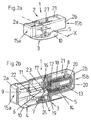
- the device 1 comprises a housing 2 which substantially is formed by two housing elements 2a, 2a which for operating the device can be pushed into each other and a drive unit housing 21 which in the situation shown in these figures is arranged within the second housing element 2b.
- the second housing element 2b On its bottom side, the second housing element 2b carries a base plate 10 providing a contact face 3 for placing the device 1 onto the skin of the body of a patient.
- This contact face 3 carries a layer 4 of skin compatible glue for fixing the base plate 10 to the skin of the body, which layer 4 is covered by a removable protecting film 5 which before use of the device 1 must be removed.
- a cannula arrangement 6 is arranged in a movable manner, which comprises a soft cannula 11 for being inserted into the tissue of the body of the patient and a guiding needle 12 extending through the fluid channel of said soft cannula 11 for temporarily stiffening it during introduction into the tissue.
- the soft cannula 11 together with the guiding needle 12 forms an insertion member 11, 12 according to the claims, wherein the soft cannula is the part of this insertion member that is intended to remain inside the tissue of the body for a longer period.
- the guiding needle 12 at the free end of the cannula arrangement 6 protrudes out of the soft cannula 11, thereby forming a puncturing tip 9 for puncturing the skin of the body of the patient when inserting the soft cannula 11 with the help of the guiding needle 12 into the tissue.
- the soft cannula 11 at its end facing away from the puncturing tip 9 is fixedly connected through material bonding to an adapter housing 7 (holder element 7 according to the claims) providing a port 16 for connecting a catheter to the housing 7 and a fluid channel 17 extending inside the housing 7 between the soft cannula 11 and the port 16, for fluidically connecting the catheter with the soft cannula 11.
- the holder element 14 is in a slidable manner received in a guiding sleeve 18 which in turn in a slidable manner is guided inside the drive unit housing 21 which in a tiltable manner around an axis X is arranged inside the second housing element 2b.
- the soft cannula 11 and the adapter housing 7 are carried by the guiding needle 12. In this state, the cannula arrangement 6 is oriented substantially parallel to a plane formed by the contact face 3.
- the device 1 furthermore comprises helical springs 8, 13 arranged in a coaxial manner within the drive unit housing 21, the function of which will in the course of the proceeding description of the drawings be described more into detail.
- the front faces 15a, 15b (activating means 15a, 15b according to the claims) of the two housing elements 2a, 2b are contacted with the fingertips of the trigger finger and thumb of one hand of the operator and are pressed towards each other.
- the two housing elements 2a, 2b are pushed into each other and the guiding sleeve 18, which carries the cannula arrangement 6, is pushed by the first housing element 2a into the drive unit housing 21 against the force of the two springs 8, 13, which both with one of their two ends abut against the guiding sleeve 18 and with their other end abut against an end of the drive unit housing 21.
- the holder element 14 travels through the centers of the springs 8, 13 and at the end, when both springs 8, 13 are completely pre-tensioned, snaps with resilient hook elements 20 formed at its end behind the end of the inner spring 13 which abuts against the end of the drive unit housing 21.
- latching rockers 27 arranged at the drive unit housing 21 snap behind lugs 28 arranged at the guiding sleeve 18, thereby arresting the guiding sleeve 18 in a state in which the springs 8, 13 are pre-tensioned.
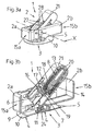
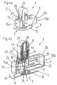
- the drive unit housing 21 with the cannula arrangement 6 carried by it is tilted around its tilting axis X from its initial position, in which the cannula arrangement 6 is oriented parallel to a plane formed by the contact face 3, over an intermediate position shown in the Figures 3a and 3b into its operating position (first position according to the claims) shown in the Figures 4a and 4b , in which the cannula arrangement 6 is oriented perpendicular to the plane formed by the contact face 3.
- the puncturing tip 9 of the guiding needle 12 is set back relative to the contact face 3.
- the tilting movement of the drive unit housing 21 is effected by a pivot formed at the drive unit housing 21 which travels in a guiding slot 22 in the first housing element 2a. As is visible especially in Fig. 4a , in this state the housing elements 2a, 2b are almost fully pushed towards each other.
- the latching rockers 27 are actuated, thereby releasing the lugs 28.
- the force of the pre-tensioned outer spring 8 now drives the guiding sleeve 18 and with it the cannula arrangement 6 in a direction perpendicular to the plane formed by the contact face 3 towards the base plate 10, where at the end of this movement (the insertion movement according to the claims) the adapter housing 7 with protrusions 23 formed at its outside snaps behind resilient hook elements 24 formed at the base plate 10 and thereby in a positive manner is coupled to the base plate 10.
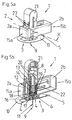
- the guiding sleeve 18 comprises two resilient hook elements 25, which abut with contact surfaces 26 that are inclined relative to the direction of the insertion movement against corresponding contact surfaces formed at the holder element 14 of the guiding needle 12.
- the hook elements 25 are radially blocked by guiding surfaces of the drive unit housing 21, so that during the insertion movement, the holder element 14 in a positive manner in movement direction is coupled to the guiding sleeve 18.
- the hook elements 25 are free to radially expand.
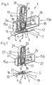
- the holder element 14 is pulled upwards through the force of the inner spring 13, thereby radially expanding the hook elements 25 by its inclined contact surfaces (see the arrows in Fig. 5c ) and pulling the guiding needle 12 out of the soft cannula 11 and out of the septum 19 of the adapter housing 7 (retracting movement according to the claims) into a position in which its puncturing tip 9 is set back relative to the contact face 3 (third position according to the claims).
- the second housing element 2b can be detached from the base plate 10 and can, together with the guiding needle 12 contained therein, be removed from the base plated 10 without any risk that its puncturing tip can be contacted by hand and can cause an injury to persons.
- This situation is shown in Fig. 7 .
Landscapes
- Health & Medical Sciences (AREA)
- Vascular Medicine (AREA)
- Engineering & Computer Science (AREA)
- Anesthesiology (AREA)
- Biomedical Technology (AREA)
- Heart & Thoracic Surgery (AREA)
- Hematology (AREA)
- Life Sciences & Earth Sciences (AREA)
- Animal Behavior & Ethology (AREA)
- General Health & Medical Sciences (AREA)
- Public Health (AREA)
- Veterinary Medicine (AREA)
- Infusion, Injection, And Reservoir Apparatuses (AREA)
Priority Applications (8)
| Application Number | Priority Date | Filing Date | Title |
|---|---|---|---|
| DK10006420.3T DK2399623T3 (da) | 2010-06-21 | 2010-06-21 | Indretning til indføring af et indføringselement i vævet på en patients legeme |
| EP15197830.1A EP3020429B1 (en) | 2010-06-21 | 2010-06-21 | Device for inserting an insertion member into the tissue of the body of a patient |
| EP10006420.3A EP2399623B1 (en) | 2010-06-21 | 2010-06-21 | Device for inserting an insertion member into the tissue of the body of a patient |
| DK15197830.1T DK3020429T3 (da) | 2010-06-21 | 2010-06-21 | Anordning til at indsætte et indsættelseselement i en patients kropsvæv |
| HK13109905.0A HK1182653B (en) | 2010-06-21 | 2011-05-26 | Device for inserting an insertion member into the tissue of the body of a patient |
| CN201180030870.8A CN102946924B (zh) | 2010-06-21 | 2011-05-26 | 用于将插入构件插入患者的身体组织的装置 |
| PCT/CH2011/000124 WO2011160244A1 (en) | 2010-06-21 | 2011-05-26 | Device for inserting an insertion member into the tissue of the body of a patient |
| US13/714,227 US9522228B2 (en) | 2010-06-21 | 2012-12-13 | Device for inserting an insertion member, or a soft member, into body tissue |
Applications Claiming Priority (1)
| Application Number | Priority Date | Filing Date | Title |
|---|---|---|---|
| EP10006420.3A EP2399623B1 (en) | 2010-06-21 | 2010-06-21 | Device for inserting an insertion member into the tissue of the body of a patient |
Related Child Applications (2)
| Application Number | Title | Priority Date | Filing Date |
|---|---|---|---|
| EP15197830.1A Division EP3020429B1 (en) | 2010-06-21 | 2010-06-21 | Device for inserting an insertion member into the tissue of the body of a patient |
| EP15197830.1A Division-Into EP3020429B1 (en) | 2010-06-21 | 2010-06-21 | Device for inserting an insertion member into the tissue of the body of a patient |
Publications (2)
| Publication Number | Publication Date |
|---|---|
| EP2399623A1 EP2399623A1 (en) | 2011-12-28 |
| EP2399623B1 true EP2399623B1 (en) | 2016-02-17 |
Family
ID=42732869
Family Applications (2)
| Application Number | Title | Priority Date | Filing Date |
|---|---|---|---|
| EP10006420.3A Active EP2399623B1 (en) | 2010-06-21 | 2010-06-21 | Device for inserting an insertion member into the tissue of the body of a patient |
| EP15197830.1A Active EP3020429B1 (en) | 2010-06-21 | 2010-06-21 | Device for inserting an insertion member into the tissue of the body of a patient |
Family Applications After (1)
| Application Number | Title | Priority Date | Filing Date |
|---|---|---|---|
| EP15197830.1A Active EP3020429B1 (en) | 2010-06-21 | 2010-06-21 | Device for inserting an insertion member into the tissue of the body of a patient |
Country Status (2)
| Country | Link |
|---|---|
| EP (2) | EP2399623B1 (da) |
| DK (2) | DK3020429T3 (da) |
Families Citing this family (1)
| Publication number | Priority date | Publication date | Assignee | Title |
|---|---|---|---|---|
| WO2012108959A1 (en) * | 2011-02-09 | 2012-08-16 | Becton, Dickinson And Company | Folding inserter for drug delivery infusion set |
Family Cites Families (7)
| Publication number | Priority date | Publication date | Assignee | Title |
|---|---|---|---|---|
| US6607509B2 (en) | 1997-12-31 | 2003-08-19 | Medtronic Minimed, Inc. | Insertion device for an insertion set and method of using the same |
| WO2002081012A2 (de) * | 2001-04-06 | 2002-10-17 | Disetronic Licensing Ag | Infusionsset |
| EP1764126B1 (de) * | 2005-09-15 | 2010-07-14 | F.Hoffmann-La Roche Ag | Insertionskopf mit Griff |
| CA2653568A1 (en) * | 2006-06-07 | 2007-12-13 | F. Hoffmann-La Roche Ag | Arrangement for introducing a liquid into the body of a patient |
| DE502007005457D1 (de) * | 2007-03-14 | 2010-12-09 | Roche Diagnostics Gmbh | Insertionskopf für medizinische oder pharmazeutische Anwendungen |
| US8323250B2 (en) * | 2007-04-30 | 2012-12-04 | Medtronic Minimed, Inc. | Adhesive patch systems and methods |
| US8002752B2 (en) * | 2007-06-25 | 2011-08-23 | Medingo, Ltd. | Protector apparatus |
-
2010
- 2010-06-21 EP EP10006420.3A patent/EP2399623B1/en active Active
- 2010-06-21 DK DK15197830.1T patent/DK3020429T3/da active
- 2010-06-21 DK DK10006420.3T patent/DK2399623T3/da active
- 2010-06-21 EP EP15197830.1A patent/EP3020429B1/en active Active
Also Published As
| Publication number | Publication date |
|---|---|
| EP2399623A1 (en) | 2011-12-28 |
| DK2399623T3 (da) | 2016-05-09 |
| EP3020429B1 (en) | 2020-07-01 |
| EP3020429A1 (en) | 2016-05-18 |
| DK3020429T3 (da) | 2020-08-31 |
Similar Documents
| Publication | Publication Date | Title |
|---|---|---|
| EP2399624B1 (en) | Device for inserting a soft member into the tissue of the body of a patient | |
| US9522228B2 (en) | Device for inserting an insertion member, or a soft member, into body tissue | |
| DK2350080T3 (da) | Usymmetriske pyrrolobenzodiazepin-dimerer til behandling af proliferative sygdomme | |
| US20240148964A1 (en) | Subcutaneous infusion device | |
| JP7203789B2 (ja) | 薬物注入装置のための一体型ばね作動式衝撃挿入 | |
| KR101243037B1 (ko) | 약물 전달 장치용 캡 | |
| EP2531242B1 (en) | Dermal access device | |
| JP2008220963A (ja) | 医療用途又は医薬用途のための挿入ヘッド | |
| MXPA04002493A (es) | Aparato auxiliar de penetracion con lanceta que comprende sistema de lanceta que esta protegido contra reutilizacion. | |
| JP2008532718A (ja) | 取付けパッド、かかる取付けパッドを備えている接着装置、およびかかる装置を患者に装着する方法 | |
| US9694135B2 (en) | Revolving multi-cartridge hypodermic syringe and method of use | |
| CN115103656B (zh) | 笔状注射器装置和注射器系统 | |
| EP2399623B1 (en) | Device for inserting an insertion member into the tissue of the body of a patient | |
| DK2742278T3 (da) | Led-lysprojektor med fresnel- eller planar-konveks-linse, i særdeleshed til biografbelysning | |
| HK1182653B (en) | Device for inserting an insertion member into the tissue of the body of a patient | |
| US20250303056A1 (en) | Semi-disposable drug delivery device | |
| CN101146569A (zh) | 安装垫、含安装垫的粘合装置及将该装置用于患者的方法 | |
| HK1125057B (en) | Insertion head for medical or pharmaceutical applications | |
| HK1135049B (en) | Insertion device for insertion heads, in particular for infusion sets | |
| HK1106460B (en) | Cap for drug delivery devices | |
| HK1135049A1 (en) | Insertion device for insertion heads, in particular for infusion sets | |
| EA040210B1 (ru) | Устройство для доставки лекарственных веществ, приводимое в действие ладонью руки |
Legal Events
| Date | Code | Title | Description |
|---|---|---|---|
| AK | Designated contracting states |
Kind code of ref document: A1 Designated state(s): AL AT BE BG CH CY CZ DE DK EE ES FI FR GB GR HR HU IE IS IT LI LT LU LV MC MK MT NL NO PL PT RO SE SI SK SM TR |
|
| AX | Request for extension of the european patent |
Extension state: BA ME RS |
|
| PUAI | Public reference made under article 153(3) epc to a published international application that has entered the european phase |
Free format text: ORIGINAL CODE: 0009012 |
|
| 17P | Request for examination filed |
Effective date: 20120607 |
|
| 17Q | First examination report despatched |
Effective date: 20121214 |
|
| RIC1 | Information provided on ipc code assigned before grant |
Ipc: A61M 5/158 20060101AFI20141208BHEP Ipc: A61M 5/00 20060101ALN20141208BHEP |
|
| GRAP | Despatch of communication of intention to grant a patent |
Free format text: ORIGINAL CODE: EPIDOSNIGR1 |
|
| INTG | Intention to grant announced |
Effective date: 20150127 |
|
| GRAP | Despatch of communication of intention to grant a patent |
Free format text: ORIGINAL CODE: EPIDOSNIGR1 |
|
| INTG | Intention to grant announced |
Effective date: 20150803 |
|
| GRAS | Grant fee paid |
Free format text: ORIGINAL CODE: EPIDOSNIGR3 |
|
| GRAA | (expected) grant |
Free format text: ORIGINAL CODE: 0009210 |
|
| AK | Designated contracting states |
Kind code of ref document: B1 Designated state(s): AL AT BE BG CH CY CZ DE DK EE ES FI FR GB GR HR HU IE IS IT LI LT LU LV MC MK MT NL NO PL PT RO SE SI SK SM TR |
|
| REG | Reference to a national code |
Ref country code: GB Ref legal event code: FG4D |
|
| REG | Reference to a national code |
Ref country code: CH Ref legal event code: EP |
|
| REG | Reference to a national code |
Ref country code: IE Ref legal event code: FG4D |
|
| REG | Reference to a national code |
Ref country code: AT Ref legal event code: REF Ref document number: 775343 Country of ref document: AT Kind code of ref document: T Effective date: 20160315 |
|
| REG | Reference to a national code |
Ref country code: DE Ref legal event code: R096 Ref document number: 602010030635 Country of ref document: DE |
|
| REG | Reference to a national code |
Ref country code: DK Ref legal event code: T3 Effective date: 20160504 |
|
| REG | Reference to a national code |
Ref country code: FR Ref legal event code: PLFP Year of fee payment: 7 |
|
| REG | Reference to a national code |
Ref country code: NL Ref legal event code: FP |
|
| REG | Reference to a national code |
Ref country code: LT Ref legal event code: MG4D |
|
| REG | Reference to a national code |
Ref country code: AT Ref legal event code: MK05 Ref document number: 775343 Country of ref document: AT Kind code of ref document: T Effective date: 20160217 |
|
| PG25 | Lapsed in a contracting state [announced via postgrant information from national office to epo] |
Ref country code: ES Free format text: LAPSE BECAUSE OF FAILURE TO SUBMIT A TRANSLATION OF THE DESCRIPTION OR TO PAY THE FEE WITHIN THE PRESCRIBED TIME-LIMIT Effective date: 20160217 Ref country code: IT Free format text: LAPSE BECAUSE OF FAILURE TO SUBMIT A TRANSLATION OF THE DESCRIPTION OR TO PAY THE FEE WITHIN THE PRESCRIBED TIME-LIMIT Effective date: 20160217 Ref country code: NO Free format text: LAPSE BECAUSE OF FAILURE TO SUBMIT A TRANSLATION OF THE DESCRIPTION OR TO PAY THE FEE WITHIN THE PRESCRIBED TIME-LIMIT Effective date: 20160517 Ref country code: FI Free format text: LAPSE BECAUSE OF FAILURE TO SUBMIT A TRANSLATION OF THE DESCRIPTION OR TO PAY THE FEE WITHIN THE PRESCRIBED TIME-LIMIT Effective date: 20160217 Ref country code: GR Free format text: LAPSE BECAUSE OF FAILURE TO SUBMIT A TRANSLATION OF THE DESCRIPTION OR TO PAY THE FEE WITHIN THE PRESCRIBED TIME-LIMIT Effective date: 20160518 |
|
| PG25 | Lapsed in a contracting state [announced via postgrant information from national office to epo] |
Ref country code: LV Free format text: LAPSE BECAUSE OF FAILURE TO SUBMIT A TRANSLATION OF THE DESCRIPTION OR TO PAY THE FEE WITHIN THE PRESCRIBED TIME-LIMIT Effective date: 20160217 Ref country code: PT Free format text: LAPSE BECAUSE OF FAILURE TO SUBMIT A TRANSLATION OF THE DESCRIPTION OR TO PAY THE FEE WITHIN THE PRESCRIBED TIME-LIMIT Effective date: 20160617 Ref country code: AT Free format text: LAPSE BECAUSE OF FAILURE TO SUBMIT A TRANSLATION OF THE DESCRIPTION OR TO PAY THE FEE WITHIN THE PRESCRIBED TIME-LIMIT Effective date: 20160217 Ref country code: SE Free format text: LAPSE BECAUSE OF FAILURE TO SUBMIT A TRANSLATION OF THE DESCRIPTION OR TO PAY THE FEE WITHIN THE PRESCRIBED TIME-LIMIT Effective date: 20160217 Ref country code: LT Free format text: LAPSE BECAUSE OF FAILURE TO SUBMIT A TRANSLATION OF THE DESCRIPTION OR TO PAY THE FEE WITHIN THE PRESCRIBED TIME-LIMIT Effective date: 20160217 Ref country code: PL Free format text: LAPSE BECAUSE OF FAILURE TO SUBMIT A TRANSLATION OF THE DESCRIPTION OR TO PAY THE FEE WITHIN THE PRESCRIBED TIME-LIMIT Effective date: 20160217 |
|
| PG25 | Lapsed in a contracting state [announced via postgrant information from national office to epo] |
Ref country code: EE Free format text: LAPSE BECAUSE OF FAILURE TO SUBMIT A TRANSLATION OF THE DESCRIPTION OR TO PAY THE FEE WITHIN THE PRESCRIBED TIME-LIMIT Effective date: 20160217 |
|
| REG | Reference to a national code |
Ref country code: DE Ref legal event code: R097 Ref document number: 602010030635 Country of ref document: DE |
|
| PG25 | Lapsed in a contracting state [announced via postgrant information from national office to epo] |
Ref country code: SK Free format text: LAPSE BECAUSE OF FAILURE TO SUBMIT A TRANSLATION OF THE DESCRIPTION OR TO PAY THE FEE WITHIN THE PRESCRIBED TIME-LIMIT Effective date: 20160217 Ref country code: CZ Free format text: LAPSE BECAUSE OF FAILURE TO SUBMIT A TRANSLATION OF THE DESCRIPTION OR TO PAY THE FEE WITHIN THE PRESCRIBED TIME-LIMIT Effective date: 20160217 Ref country code: RO Free format text: LAPSE BECAUSE OF FAILURE TO SUBMIT A TRANSLATION OF THE DESCRIPTION OR TO PAY THE FEE WITHIN THE PRESCRIBED TIME-LIMIT Effective date: 20160217 Ref country code: SM Free format text: LAPSE BECAUSE OF FAILURE TO SUBMIT A TRANSLATION OF THE DESCRIPTION OR TO PAY THE FEE WITHIN THE PRESCRIBED TIME-LIMIT Effective date: 20160217 |
|
| PLBE | No opposition filed within time limit |
Free format text: ORIGINAL CODE: 0009261 |
|
| STAA | Information on the status of an ep patent application or granted ep patent |
Free format text: STATUS: NO OPPOSITION FILED WITHIN TIME LIMIT |
|
| PG25 | Lapsed in a contracting state [announced via postgrant information from national office to epo] |
Ref country code: BE Free format text: LAPSE BECAUSE OF FAILURE TO SUBMIT A TRANSLATION OF THE DESCRIPTION OR TO PAY THE FEE WITHIN THE PRESCRIBED TIME-LIMIT Effective date: 20160217 |
|
| 26N | No opposition filed |
Effective date: 20161118 |
|
| PG25 | Lapsed in a contracting state [announced via postgrant information from national office to epo] |
Ref country code: MC Free format text: LAPSE BECAUSE OF FAILURE TO SUBMIT A TRANSLATION OF THE DESCRIPTION OR TO PAY THE FEE WITHIN THE PRESCRIBED TIME-LIMIT Effective date: 20160217 |
|
| PG25 | Lapsed in a contracting state [announced via postgrant information from national office to epo] |
Ref country code: BG Free format text: LAPSE BECAUSE OF FAILURE TO SUBMIT A TRANSLATION OF THE DESCRIPTION OR TO PAY THE FEE WITHIN THE PRESCRIBED TIME-LIMIT Effective date: 20160517 Ref country code: SI Free format text: LAPSE BECAUSE OF FAILURE TO SUBMIT A TRANSLATION OF THE DESCRIPTION OR TO PAY THE FEE WITHIN THE PRESCRIBED TIME-LIMIT Effective date: 20160217 |
|
| REG | Reference to a national code |
Ref country code: IE Ref legal event code: MM4A |
|
| REG | Reference to a national code |
Ref country code: FR Ref legal event code: PLFP Year of fee payment: 8 |
|
| PG25 | Lapsed in a contracting state [announced via postgrant information from national office to epo] |
Ref country code: IE Free format text: LAPSE BECAUSE OF NON-PAYMENT OF DUE FEES Effective date: 20160621 |
|
| REG | Reference to a national code |
Ref country code: FR Ref legal event code: PLFP Year of fee payment: 9 |
|
| PG25 | Lapsed in a contracting state [announced via postgrant information from national office to epo] |
Ref country code: CY Free format text: LAPSE BECAUSE OF FAILURE TO SUBMIT A TRANSLATION OF THE DESCRIPTION OR TO PAY THE FEE WITHIN THE PRESCRIBED TIME-LIMIT Effective date: 20160217 Ref country code: HU Free format text: LAPSE BECAUSE OF FAILURE TO SUBMIT A TRANSLATION OF THE DESCRIPTION OR TO PAY THE FEE WITHIN THE PRESCRIBED TIME-LIMIT; INVALID AB INITIO Effective date: 20100621 |
|
| PG25 | Lapsed in a contracting state [announced via postgrant information from national office to epo] |
Ref country code: IS Free format text: LAPSE BECAUSE OF FAILURE TO SUBMIT A TRANSLATION OF THE DESCRIPTION OR TO PAY THE FEE WITHIN THE PRESCRIBED TIME-LIMIT Effective date: 20160217 Ref country code: LU Free format text: LAPSE BECAUSE OF NON-PAYMENT OF DUE FEES Effective date: 20160621 Ref country code: TR Free format text: LAPSE BECAUSE OF FAILURE TO SUBMIT A TRANSLATION OF THE DESCRIPTION OR TO PAY THE FEE WITHIN THE PRESCRIBED TIME-LIMIT Effective date: 20160217 Ref country code: MK Free format text: LAPSE BECAUSE OF FAILURE TO SUBMIT A TRANSLATION OF THE DESCRIPTION OR TO PAY THE FEE WITHIN THE PRESCRIBED TIME-LIMIT Effective date: 20160217 Ref country code: HR Free format text: LAPSE BECAUSE OF FAILURE TO SUBMIT A TRANSLATION OF THE DESCRIPTION OR TO PAY THE FEE WITHIN THE PRESCRIBED TIME-LIMIT Effective date: 20160217 Ref country code: MT Free format text: LAPSE BECAUSE OF NON-PAYMENT OF DUE FEES Effective date: 20160630 |
|
| PG25 | Lapsed in a contracting state [announced via postgrant information from national office to epo] |
Ref country code: AL Free format text: LAPSE BECAUSE OF FAILURE TO SUBMIT A TRANSLATION OF THE DESCRIPTION OR TO PAY THE FEE WITHIN THE PRESCRIBED TIME-LIMIT Effective date: 20160217 |
|
| REG | Reference to a national code |
Ref country code: DE Ref legal event code: R081 Ref document number: 602010030635 Country of ref document: DE Owner name: ROCHE DIABETES CARE GMBH, DE Free format text: FORMER OWNER: ROCHE DIAGNOSTICS GMBH, 68305 MANNHEIM, DE |
|
| PGFP | Annual fee paid to national office [announced via postgrant information from national office to epo] |
Ref country code: NL Payment date: 20230511 Year of fee payment: 14 |
|
| REG | Reference to a national code |
Ref country code: NL Ref legal event code: MM Effective date: 20240701 |
|
| PG25 | Lapsed in a contracting state [announced via postgrant information from national office to epo] |
Ref country code: NL Free format text: LAPSE BECAUSE OF NON-PAYMENT OF DUE FEES Effective date: 20240701 |
|
| PG25 | Lapsed in a contracting state [announced via postgrant information from national office to epo] |
Ref country code: NL Free format text: LAPSE BECAUSE OF NON-PAYMENT OF DUE FEES Effective date: 20240701 |
|
| PGFP | Annual fee paid to national office [announced via postgrant information from national office to epo] |
Ref country code: DE Payment date: 20250520 Year of fee payment: 16 |
|
| PGFP | Annual fee paid to national office [announced via postgrant information from national office to epo] |
Ref country code: GB Payment date: 20250520 Year of fee payment: 16 Ref country code: DK Payment date: 20250520 Year of fee payment: 16 |
|
| PGFP | Annual fee paid to national office [announced via postgrant information from national office to epo] |
Ref country code: FR Payment date: 20250520 Year of fee payment: 16 |
|
| PGFP | Annual fee paid to national office [announced via postgrant information from national office to epo] |
Ref country code: CH Payment date: 20250701 Year of fee payment: 16 |