EP2399692A1 - Moule continu pour la coulée d'éléments en coulée à partir d'un métal en fusion - Google Patents
Moule continu pour la coulée d'éléments en coulée à partir d'un métal en fusion Download PDFInfo
- Publication number
- EP2399692A1 EP2399692A1 EP11171279A EP11171279A EP2399692A1 EP 2399692 A1 EP2399692 A1 EP 2399692A1 EP 11171279 A EP11171279 A EP 11171279A EP 11171279 A EP11171279 A EP 11171279A EP 2399692 A1 EP2399692 A1 EP 2399692A1
- Authority
- EP
- European Patent Office
- Prior art keywords
- mold
- permanent
- casting
- package
- continuous casting
- Prior art date
- Legal status (The legal status is an assumption and is not a legal conclusion. Google has not performed a legal analysis and makes no representation as to the accuracy of the status listed.)
- Granted
Links
Images

Classifications
-
- B—PERFORMING OPERATIONS; TRANSPORTING
- B22—CASTING; POWDER METALLURGY
- B22C—FOUNDRY MOULDING
- B22C9/00—Moulds or cores; Moulding processes
- B22C9/06—Permanent moulds for shaped castings
-
- B—PERFORMING OPERATIONS; TRANSPORTING
- B22—CASTING; POWDER METALLURGY
- B22C—FOUNDRY MOULDING
- B22C9/00—Moulds or cores; Moulding processes
- B22C9/02—Sand moulds or like moulds for shaped castings
-
- B—PERFORMING OPERATIONS; TRANSPORTING
- B22—CASTING; POWDER METALLURGY
- B22C—FOUNDRY MOULDING
- B22C9/00—Moulds or cores; Moulding processes
- B22C9/10—Cores; Manufacture or installation of cores
- B22C9/103—Multipart cores
Definitions
- the invention relates to a permanent casting mold for casting a casting from a molten metal, which is composed of at least two permanent mold parts delimiting the mold cavity of the permanent casting mold from the environment, which remain intact when the casting is removed from the mold.
- Continuous casting molds of this type also known as "casting molds" in technical terminology, are used, for example, in mass production to cast cylinder heads for internal combustion engines from an aluminum melt.
- the object of the invention was to provide a way, a complex shaped component, as it represents a cylinder head with a molded on the type of the above cylinder head design turbocharger housing, reliable in high volumes and cost casting technology to finished.
- a permanent casting mold according to the invention for casting a casting from a molten metal is composed of at least two permanent mold parts which delimit the cavity of the permanent casting mold from the environment.
- the permanent moldings are characterized by the fact that they are not destroyed during removal of the casting, but preserved and can be reused accordingly for many casting runs.
- casting cores or molded parts can also be positioned as usual in a permanent casting mold according to the invention within the mold cavity, which decay into many free-flowing individual parts as a result of targeted mechanical force or the thermal stresses occurring during the casting. Casting cores of this type are required, for example, in permanent casting molds if channels, cavities, etc. are to be formed within the respective casting.
- this mold package consists of a material which breaks when the cast part is completely removed from the mold and surrounds a mold cavity section.
- the mold cavity section surrounded by the mold package is in communication with the mold cavity of the permanent mold, so that melt filled into the mold cavity of the permanent mold passes into the mold cavity section of the mold package and vice versa.
- the permanent casting mold is supplemented by a mold package which, viewed individually, is designed in the manner of a lost casting mold and is newly created for each casting process.
- a mold package which, viewed individually, is designed in the manner of a lost casting mold and is newly created for each casting process.
- the invention combines the advantages of a permanent mold with the advantages of a mold package designed as a lost mold. Since the volume of the functional part respectively imaged by the mold package is small compared to the volume that is imaged in the mold cavity surrounded by the permanent mold parts, the expense to be taken into account for the production of the mold package is also in relation to the advantages resulting from the design according to the invention a mold can be achieved, low.
- the mold package associated parts of the permanent mold and the mold package can be designed so that in the finished composite permanent mold the mold package is applied to an outer surface of the permanent mold.
- a separate seal may be provided for sealing the existing between the permanent mold and the mold package joining gap. This can for example also be arranged so that it acts between the peripheral wall of the opening, which is associated with the mold package, and a corresponding surface of the mold package.
- At least one first mold element and formed on at least one of the Treasureg cashformmaschine a corresponding to the first mold element shaped second mold element may be formed on the mold package, the form-fitting with the mold element of the mold package cooperates.
- the respective shaping elements acting in the manner of core marks can be designed such that they not only define the position of the mold package in relation to the permanent moldings, but also ensure a captive hold of the mold package on the associated permanent moldings.
- the opening of the permanent mold associated with the mold package may contribute to the proper alignment of the mold package when the opening of the permanent mold associated with the mold package widens, at least in sections, starting from the mold cavity of the permanent mold in the direction of the outer surface of the permanent mold.
- the opening is then designed in the manner of a funnel in such a way that the mold package inserted into the opening is automatically aligned during its mounting on the surfaces of the widening sections lying against it.
- the edge region, which surrounds the opening associated with the mold package may be designed tapering at least in sections in the direction of the mold cavity of the permanent mold or in the manner of a throat.
- the mold package forming the functional element to be molded will typically be composed of two or more moldings or mold cores.
- the mold package can map a functional part, which is integrally connected to the cylinder head with finished cast cylinder head and has at least one channel which is connected without interruption with a channel of the cylinder head.
- a functional part may be, for example, the housing or a housing part of a turbocharger.
- the mold package may, for example, moldings, through which the outer shape of the housing or housing part is determined, and mold cores, which image the exhaust passage and an optionally additionally provided cooling fluid channel in the housing.
- the mold package then comprises a first mold core which images a water channel of the functional part connected to the water jacket of the cylinder head to be cast, and a second mold core which images an exhaust gas duct connected to an exhaust pipe of the cylinder head.
- a continuous casting mold which is supplemented according to the invention by a mold package which is made from a mold material which breaks down into many individual parts during removal from the mold, is suitable in particular for producing cast parts from a light metal melt, in particular an aluminum melt, since the use of such light metal melts is particularly advantageous
- Benefit from the chill casting in combination with the benefits of Formvolsses can be used to produce, for example, complex cylinder head designs for internal combustion engines, which on the one hand optimal Function integration and on the other hand, a minimization of production costs.
- At least one molding element may be provided on the casting mold for imaging a first receiving point on the casting.
- a first reception point or several such initial reception points are used in particular in automated machining as a starting point for the measurement of the geometry of the respective casting.
- the Clearage determine the "zero points" for the alignment of the machining tool or the respective workpiece to be machined in the x-, y- and z-direction.
- the portion of the casting shown in the destructible mold package is a special one Machining must be subjected to the particular requirements, for example, in terms of geometry, in particular the correct position positioning of the respective processing sections, provided, it may be useful if an additional mold element is provided on the mold, which at the imaged in the mold package section of Cast part forms an additional Clearageyak.
- This additional initial reception point can form the basis for an additional reference system which is independent of the reference system, which is based on the initial reception generally provided on the casting.
- This possibility proves to be particularly advantageous if an exhaust-gas turbocharger housing is depicted in the mold package, the mounting surface of which and the machined functional geometries for the turbocharger to be assembled require machining performed with extreme precision.
- the permanent mold 1 is mounted on a support plate 2.
- the carrier plate 2 is arranged for example on a transport system, not shown, which transports the permanent mold 1 to a casting station, also not shown here.
- the permanent casting mold 1 is composed of a molded part 3, which is usually made of molding sand, and of several permanent casting moldings, of which the permanent mold parts 4, 5, 6 are visible here.
- the molded part 3 forms the cover, the permanent mold part 4 a first side wall, the permanent mold part 6 a second side wall and the permanent mold part 5 a bottom of the permanent mold 1.
- the permanent mold parts of the permanent mold 1 can be made in a known manner from a suitable steel, the so high temperature and wear resistant is that the permanent moldings can be reused for a large number of casting operations.
- the permanent mold parts of the permanent mold 1 define a mold cavity 7 of the permanent mold 1 with respect to the environment U and have on their the mold cavity 7 associated side mold elements 8.9, through which the outer shape of the cylinder head to be cast is displayed.
- the mold core 12 which is arranged at a distance between the mold cores 10, 11, forms an exhaust gas duct integrated into the cylinder head to be cast, by means of which, in accordance with FIG EP 2 143 926 A1 described development, the exhaust gas outlets of the cylinder head to be cast are performed together to an outlet opening.
- the one side wall of the permanent mold 1 forming permanent mold part 5 is formed starting from the edge, which is assigned to the lid of the permanent mold 1 forming mold part 3, an opening 13 which extends in the direction of the opposite edge.
- the mandrels 10,11,12 are each designed so that they end at the opening 13 and project into the opening 13 of the permanent mold 1.
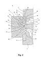
- the width of the opening 13 is at the same time dimensioned so that it receives a projection 20 of a mold package 21, which is arranged on the outside of the permanent mold part 6.
- This projection 20 of the mold package 21 fills the opening 13 of the permanent mold 1 completely and lies with its laterally beyond the projection 20, the permanent mold part 6 associated wall surfaces close to the outer surface of the permanent mold part 6.
- the split in the vertical direction in the present embodiment mold package 21 is made of several moldings 22,23 and mold cores 24,25 composed, which are each prepared in a conventional manner from a per se known, mixed with a suitable binder molding sand.
- the mold part 22 forms one half of the block-shaped mold package 21 in the assembled state, while the other half of the mold package 21 is formed by the mold part 23.
- the mold parts 22, 23 enclose a mold cavity section 26 in which the mold cores 24, 25 are arranged and which is open in the area of the end face of the projection 20 seated in the opening 13 of the permanent mold 1 for the mold cavity 7 delimited by the permanent mold parts 4-6.
- the mold package 21 is used for the simultaneous integral casting of a housing for an exhaust gas-driven, provided with a water-cooled turbocharger to be poured in the permanent mold 1 cylinder head.
- the one mold core 24 of the mold package 21 forms a water jacket channel of the housing to be cast.
- the mandrel 24 has a curved shape in the manner of a spiral or a screw. That in the representation in Fig. 2 lower end 27 of the mandrel 24 is to be positioned and shaped so that this end flush with its face fully flushed and accurately positioned at its associated end face of the mandrel 11 in sitting at the permanent mold part 6 mold package 21, the lower part of the water jacket to be cast Cylinder head maps.
- the second mold core 25 of the mold package 21 forms a waste gas channel which is hot in practical use and is seated in the space delimited by the mold core 24 and likewise has a helical shape.
- lower end portion 30 is positioned and shaped so that its face flush over the entire surface of its associated end face of the mold core 12, which images the integrated exhaust duct of the cylinder head to be cast.
- peg-shaped projection 31 Starting from the lower end portion 30 of the mandrel 25 follows the contour of the mandrel 24 in a formed at its other end, peg-shaped projection 31 whose longitudinal axis L is usually parallel to the flat outer surface of the permanent mold part 6 extends.
- the projection 31 is seated with its free end positively in a correspondingly shaped, not visible here recess of the molding 22 and forms at the housing to be cast from an outlet from which can later accommodate the impeller of the turbocharger.
- Both between the mold cavity portion 26 delimiting inner surfaces 32 of the mold parts 22,23 and the outer surface 34 facing them of the mold core 24 and between the inner, the mold core 25 facing surface 35 of the mold core 24 and the mold core 24 facing peripheral surface 36 is continuous a substantially constant distance. Accordingly, in the mold cavity portion 26 of the mold package 21, a first spiral outer channel 37 and, separated therefrom, a second, likewise spiral, inner channel 38 are formed. Both channels 37, 38 are connected to the permanent mold part 6 mounted mold package 21 with their one as with their other end each uninterruptible with a free, not occupied by mandrels area of the mold cavity 7 of the permanent mold 1.
- the melt flows into the channels 37, 38 of the mold package 21 without interruption when a certain fill level is reached, until these are likewise completely filled.
- cylinder head formed in the outer channel 38 light metal correspondingly forms the outer wall of the integrally cast on the cylinder head housing for the turbocharger, while the material solidified in the channel 37 by the Mold core 24 demarcated water jacket of the turbocharger housing relative to the illustrated by the mold core 25 exhaust passage of the turbocharger.
- the demolding of the cast on the cylinder head turbocharger housing is done in a conventional manner in that the mold parts 22,23 and the mandrels 24,25 are destroyed by the action of external forces. This can be done for example by shaking the cylinder head, as is usually carried out to destroy the sitting in the mold cavity 7 mandrels 10 - 12 and trickle out of the finished cylinder head.
- the positionally correct orientation of the mold package 21 on the permanent mold part 6 or in the opening 13 can also be supported by the fact that the edge surface portions surrounding the opening 13 at least in the region of Fig. 2 Lower edge portion 14 is tapered starting from its the mold cavity 7 associated edge in the direction of the outer surface of the permanent mold part 6 so that the opening 13 extends at least in this area in the direction of the environment U in the manner of a funnel, the opening 13 in the direction of the mold cavity 7 so narrowed conically.
- the surface portion of the projection 20 of the mold package 21 assigned to this bevelled portion 14 is bevelled in a corresponding manner, the mold package 21 is centered automatically in its position on the permanent mold part 6, at least in the direction of the height of the permanent mold 1.
- the mold package 21 is supported by a bracket 41.
- the support plate 2 may be formed in a conventional manner, a core mark on which the mold package 21 is fixed positively with respect to its position relative to the associated permanent mold part 6.
Landscapes
- Engineering & Computer Science (AREA)
- Mechanical Engineering (AREA)
- Molds, Cores, And Manufacturing Methods Thereof (AREA)
Applications Claiming Priority (1)
| Application Number | Priority Date | Filing Date | Title |
|---|---|---|---|
| DE201010025285 DE102010025285A1 (de) | 2010-06-28 | 2010-06-28 | Dauergießform zum Gießen von Gussstücken aus einer Metallschmelze |
Publications (2)
| Publication Number | Publication Date |
|---|---|
| EP2399692A1 true EP2399692A1 (fr) | 2011-12-28 |
| EP2399692B1 EP2399692B1 (fr) | 2015-02-18 |
Family
ID=44721165
Family Applications (1)
| Application Number | Title | Priority Date | Filing Date |
|---|---|---|---|
| EP20110171279 Active EP2399692B1 (fr) | 2010-06-28 | 2011-06-24 | Moule pour la coulée d'éléments en coulée à partir d'un métal en fusion |
Country Status (2)
| Country | Link |
|---|---|
| EP (1) | EP2399692B1 (fr) |
| DE (1) | DE102010025285A1 (fr) |
Cited By (5)
| Publication number | Priority date | Publication date | Assignee | Title |
|---|---|---|---|---|
| CN104741547A (zh) * | 2015-04-01 | 2015-07-01 | 无锡蠡湖增压技术股份有限公司 | 一种带热碰模的压气壳用无砂芯金属模具 |
| CN106180577A (zh) * | 2016-09-28 | 2016-12-07 | 江苏华培动力科技有限公司 | 双涡流涡壳砂芯无缝组合工艺 |
| CN106424582A (zh) * | 2016-10-28 | 2017-02-22 | 江苏华培动力科技有限公司 | 涡轮增压器壳体铸造用砂芯成型工艺 |
| CN112566739A (zh) * | 2018-11-09 | 2021-03-26 | 宝马股份公司 | 用于制造曲轴箱的锭模和方法 |
| CN116493545A (zh) * | 2022-01-27 | 2023-07-28 | 大众汽车股份公司 | 用于硬模铸造的铸造模具 |
Families Citing this family (1)
| Publication number | Priority date | Publication date | Assignee | Title |
|---|---|---|---|---|
| DE102017211876B3 (de) | 2017-07-12 | 2018-08-16 | Bayerische Motoren Werke Aktiengesellschaft | Kokille sowie Verfahren zum Herstellen eines Bauteils |
Citations (3)
| Publication number | Priority date | Publication date | Assignee | Title |
|---|---|---|---|---|
| EP0872295A1 (fr) * | 1997-04-15 | 1998-10-21 | Wärtsilä NSD Schweiz AG | Moule de coulage et procédé de fabrication de pièces coulées creuses et pièces coulées creuses |
| EP1536141A1 (fr) * | 2003-11-28 | 2005-06-01 | BorgWarner Inc. | Carter pour un turbocompresseur |
| EP2143922A1 (fr) | 2008-07-11 | 2010-01-13 | Ford Global Technologies, LLC | Culasse avec collecteur d'échappement et turbocompresseur |
Family Cites Families (4)
| Publication number | Priority date | Publication date | Assignee | Title |
|---|---|---|---|---|
| DE202004020207U1 (de) * | 2004-12-27 | 2005-04-07 | Univ Magdeburg Tech | Einrichtung zum Schwerkraftgießen von Leichtmetallgussteilen im Kokillen-Gießverfahren |
| US7438117B2 (en) * | 2006-01-19 | 2008-10-21 | Gm Global Technology Operations, Inc. | Cylinder block casting bulkhead window formation |
| DE102007004050B4 (de) * | 2007-01-22 | 2010-03-18 | Ks Aluminium-Technologie Gmbh | Vorrichtung zum Herstellen eines Zylinderkurbelgehäuses |
| DE102007030482B4 (de) * | 2007-06-30 | 2018-12-20 | Dr. Ing. H.C. F. Porsche Aktiengesellschaft | Kühlkanäle im Zylinderkopf einer Brennkraftmaschine |
-
2010
- 2010-06-28 DE DE201010025285 patent/DE102010025285A1/de not_active Withdrawn
-
2011
- 2011-06-24 EP EP20110171279 patent/EP2399692B1/fr active Active
Patent Citations (4)
| Publication number | Priority date | Publication date | Assignee | Title |
|---|---|---|---|---|
| EP0872295A1 (fr) * | 1997-04-15 | 1998-10-21 | Wärtsilä NSD Schweiz AG | Moule de coulage et procédé de fabrication de pièces coulées creuses et pièces coulées creuses |
| EP1536141A1 (fr) * | 2003-11-28 | 2005-06-01 | BorgWarner Inc. | Carter pour un turbocompresseur |
| EP2143922A1 (fr) | 2008-07-11 | 2010-01-13 | Ford Global Technologies, LLC | Culasse avec collecteur d'échappement et turbocompresseur |
| EP2143926A1 (fr) | 2008-07-11 | 2010-01-13 | Ford Global Technologies, LLC | Combinaison d'une culasse et d'une turbine |
Cited By (6)
| Publication number | Priority date | Publication date | Assignee | Title |
|---|---|---|---|---|
| CN104741547A (zh) * | 2015-04-01 | 2015-07-01 | 无锡蠡湖增压技术股份有限公司 | 一种带热碰模的压气壳用无砂芯金属模具 |
| CN106180577A (zh) * | 2016-09-28 | 2016-12-07 | 江苏华培动力科技有限公司 | 双涡流涡壳砂芯无缝组合工艺 |
| CN106180577B (zh) * | 2016-09-28 | 2018-11-27 | 江苏华培动力科技有限公司 | 双涡流涡壳砂芯无缝组合工艺 |
| CN106424582A (zh) * | 2016-10-28 | 2017-02-22 | 江苏华培动力科技有限公司 | 涡轮增压器壳体铸造用砂芯成型工艺 |
| CN112566739A (zh) * | 2018-11-09 | 2021-03-26 | 宝马股份公司 | 用于制造曲轴箱的锭模和方法 |
| CN116493545A (zh) * | 2022-01-27 | 2023-07-28 | 大众汽车股份公司 | 用于硬模铸造的铸造模具 |
Also Published As
| Publication number | Publication date |
|---|---|
| EP2399692B1 (fr) | 2015-02-18 |
| DE102010025285A1 (de) | 2011-12-29 |
Similar Documents
| Publication | Publication Date | Title |
|---|---|---|
| DE102014101080B3 (de) | Vorrichtung zur Herstellung eines Zylinderkurbelgehäuses im Niederdruck- oder Schwerkraftgießverfahren | |
| EP2399692B1 (fr) | Moule pour la coulée d'éléments en coulée à partir d'un métal en fusion | |
| EP2091678B1 (fr) | Moule de coulée pour la coulée d'une pièce et utilisation de ce moule de coulée | |
| EP2945760B1 (fr) | Moule permettant d'obtenir des pièces en fonte, en particulier des blocs-cylindres et des culasses, avec raccordement fonctionnel de la masselotte | |
| DE2738635A1 (de) | Mehrfachgiessform | |
| EP3570992A1 (fr) | Moule de coulée pour couler des pièces coulées façonnées complexes et utilisation d'un tel moule de coulée | |
| EP0872295B1 (fr) | Moule de coulage et procédé de fabrication de pièces coulées creuses et pièces coulées creuses | |
| DE112014004716T5 (de) | Verfahren und Gießmaschine zum Gießen von Metallteilen | |
| DE69908212T2 (de) | Verfahren und Einrichtung zum Giessen von Teilen aus Leichtmetall-Legierungen | |
| DE102013021197B3 (de) | Verfahren zum Herstellen eines Gießkerns sowie Gießkern | |
| DE69313180T2 (de) | Giessform zur Herstellung von dünnwandigen Gussstücken durch Schwerkraftgiessen | |
| DE10153721B4 (de) | Gießwerkzeug zur Herstellung eines Zylinderkurbelgehäuses | |
| EP1981667B1 (fr) | Procédé de montage d'un moule pour couler une pièce en métal fondu | |
| EP1002602A1 (fr) | Dispositif et procédé pour la fabrication d'un bloc moteur | |
| DE102010025286B4 (de) | Leichtmetallgussteil für einen Verbrennungsmotor | |
| EP1948374B1 (fr) | Moule permanent et piece de coulee inseree | |
| EP0231520A1 (fr) | Procédé et dispositif pour le raccordement d'un nouveau lingot continu dans une installation de coulée continue | |
| EP1204516B1 (fr) | Procede de realisation d'un corps creux par la technique de moulage a noyau fusible | |
| DE102007015051A1 (de) | Kern für Druckgiessformen | |
| EP1872885A2 (fr) | Bloc moteur et procédé de fabrication | |
| DE102019110785A1 (de) | Verfahren für das semi-permanente gussverfahren | |
| DE112011102887B4 (de) | Form, Verwendung und Entwurfsverfahren der Form | |
| EP0656819A1 (fr) | Procede et dispositifs permettant de couler des elements | |
| DE102005030814B4 (de) | Gussform für den Metallguss | |
| EP3427859A1 (fr) | Noyau de coulée pour une armature sanitaire et armature sanitaire |
Legal Events
| Date | Code | Title | Description |
|---|---|---|---|
| AK | Designated contracting states |
Kind code of ref document: A1 Designated state(s): AL AT BE BG CH CY CZ DE DK EE ES FI FR GB GR HR HU IE IS IT LI LT LU LV MC MK MT NL NO PL PT RO RS SE SI SK SM TR |
|
| AX | Request for extension of the european patent |
Extension state: BA ME |
|
| PUAI | Public reference made under article 153(3) epc to a published international application that has entered the european phase |
Free format text: ORIGINAL CODE: 0009012 |
|
| 17P | Request for examination filed |
Effective date: 20120625 |
|
| GRAP | Despatch of communication of intention to grant a patent |
Free format text: ORIGINAL CODE: EPIDOSNIGR1 |
|
| INTG | Intention to grant announced |
Effective date: 20140724 |
|
| GRAP | Despatch of communication of intention to grant a patent |
Free format text: ORIGINAL CODE: EPIDOSNIGR1 |
|
| INTG | Intention to grant announced |
Effective date: 20140825 |
|
| GRAS | Grant fee paid |
Free format text: ORIGINAL CODE: EPIDOSNIGR3 |
|
| GRAA | (expected) grant |
Free format text: ORIGINAL CODE: 0009210 |
|
| AK | Designated contracting states |
Kind code of ref document: B1 Designated state(s): AL AT BE BG CH CY CZ DE DK EE ES FI FR GB GR HR HU IE IS IT LI LT LU LV MC MK MT NL NO PL PT RO RS SE SI SK SM TR |
|
| REG | Reference to a national code |
Ref country code: GB Ref legal event code: FG4D Free format text: NOT ENGLISH |
|
| REG | Reference to a national code |
Ref country code: CH Ref legal event code: EP |
|
| REG | Reference to a national code |
Ref country code: AT Ref legal event code: REF Ref document number: 710439 Country of ref document: AT Kind code of ref document: T Effective date: 20150315 |
|
| REG | Reference to a national code |
Ref country code: IE Ref legal event code: FG4D Free format text: LANGUAGE OF EP DOCUMENT: GERMAN |
|
| REG | Reference to a national code |
Ref country code: DE Ref legal event code: R096 Ref document number: 502011005884 Country of ref document: DE Effective date: 20150402 |
|
| REG | Reference to a national code |
Ref country code: NL Ref legal event code: VDEP Effective date: 20150218 |
|
| REG | Reference to a national code |
Ref country code: LT Ref legal event code: MG4D |
|
| PG25 | Lapsed in a contracting state [announced via postgrant information from national office to epo] |
Ref country code: FI Free format text: LAPSE BECAUSE OF FAILURE TO SUBMIT A TRANSLATION OF THE DESCRIPTION OR TO PAY THE FEE WITHIN THE PRESCRIBED TIME-LIMIT Effective date: 20150218 Ref country code: HR Free format text: LAPSE BECAUSE OF FAILURE TO SUBMIT A TRANSLATION OF THE DESCRIPTION OR TO PAY THE FEE WITHIN THE PRESCRIBED TIME-LIMIT Effective date: 20150218 Ref country code: NO Free format text: LAPSE BECAUSE OF FAILURE TO SUBMIT A TRANSLATION OF THE DESCRIPTION OR TO PAY THE FEE WITHIN THE PRESCRIBED TIME-LIMIT Effective date: 20150518 Ref country code: SE Free format text: LAPSE BECAUSE OF FAILURE TO SUBMIT A TRANSLATION OF THE DESCRIPTION OR TO PAY THE FEE WITHIN THE PRESCRIBED TIME-LIMIT Effective date: 20150218 Ref country code: LT Free format text: LAPSE BECAUSE OF FAILURE TO SUBMIT A TRANSLATION OF THE DESCRIPTION OR TO PAY THE FEE WITHIN THE PRESCRIBED TIME-LIMIT Effective date: 20150218 Ref country code: ES Free format text: LAPSE BECAUSE OF FAILURE TO SUBMIT A TRANSLATION OF THE DESCRIPTION OR TO PAY THE FEE WITHIN THE PRESCRIBED TIME-LIMIT Effective date: 20150218 |
|
| PG25 | Lapsed in a contracting state [announced via postgrant information from national office to epo] |
Ref country code: RS Free format text: LAPSE BECAUSE OF FAILURE TO SUBMIT A TRANSLATION OF THE DESCRIPTION OR TO PAY THE FEE WITHIN THE PRESCRIBED TIME-LIMIT Effective date: 20150218 Ref country code: NL Free format text: LAPSE BECAUSE OF FAILURE TO SUBMIT A TRANSLATION OF THE DESCRIPTION OR TO PAY THE FEE WITHIN THE PRESCRIBED TIME-LIMIT Effective date: 20150218 Ref country code: LV Free format text: LAPSE BECAUSE OF FAILURE TO SUBMIT A TRANSLATION OF THE DESCRIPTION OR TO PAY THE FEE WITHIN THE PRESCRIBED TIME-LIMIT Effective date: 20150218 Ref country code: GR Free format text: LAPSE BECAUSE OF FAILURE TO SUBMIT A TRANSLATION OF THE DESCRIPTION OR TO PAY THE FEE WITHIN THE PRESCRIBED TIME-LIMIT Effective date: 20150519 Ref country code: IS Free format text: LAPSE BECAUSE OF FAILURE TO SUBMIT A TRANSLATION OF THE DESCRIPTION OR TO PAY THE FEE WITHIN THE PRESCRIBED TIME-LIMIT Effective date: 20150618 |
|
| PG25 | Lapsed in a contracting state [announced via postgrant information from national office to epo] |
Ref country code: CZ Free format text: LAPSE BECAUSE OF FAILURE TO SUBMIT A TRANSLATION OF THE DESCRIPTION OR TO PAY THE FEE WITHIN THE PRESCRIBED TIME-LIMIT Effective date: 20150218 Ref country code: RO Free format text: LAPSE BECAUSE OF FAILURE TO SUBMIT A TRANSLATION OF THE DESCRIPTION OR TO PAY THE FEE WITHIN THE PRESCRIBED TIME-LIMIT Effective date: 20150218 Ref country code: SK Free format text: LAPSE BECAUSE OF FAILURE TO SUBMIT A TRANSLATION OF THE DESCRIPTION OR TO PAY THE FEE WITHIN THE PRESCRIBED TIME-LIMIT Effective date: 20150218 Ref country code: DK Free format text: LAPSE BECAUSE OF FAILURE TO SUBMIT A TRANSLATION OF THE DESCRIPTION OR TO PAY THE FEE WITHIN THE PRESCRIBED TIME-LIMIT Effective date: 20150218 Ref country code: EE Free format text: LAPSE BECAUSE OF FAILURE TO SUBMIT A TRANSLATION OF THE DESCRIPTION OR TO PAY THE FEE WITHIN THE PRESCRIBED TIME-LIMIT Effective date: 20150218 |
|
| REG | Reference to a national code |
Ref country code: DE Ref legal event code: R097 Ref document number: 502011005884 Country of ref document: DE |
|
| PG25 | Lapsed in a contracting state [announced via postgrant information from national office to epo] |
Ref country code: PL Free format text: LAPSE BECAUSE OF FAILURE TO SUBMIT A TRANSLATION OF THE DESCRIPTION OR TO PAY THE FEE WITHIN THE PRESCRIBED TIME-LIMIT Effective date: 20150218 |
|
| PLBE | No opposition filed within time limit |
Free format text: ORIGINAL CODE: 0009261 |
|
| STAA | Information on the status of an ep patent application or granted ep patent |
Free format text: STATUS: NO OPPOSITION FILED WITHIN TIME LIMIT |
|
| 26N | No opposition filed |
Effective date: 20151119 |
|
| PG25 | Lapsed in a contracting state [announced via postgrant information from national office to epo] |
Ref country code: MC Free format text: LAPSE BECAUSE OF FAILURE TO SUBMIT A TRANSLATION OF THE DESCRIPTION OR TO PAY THE FEE WITHIN THE PRESCRIBED TIME-LIMIT Effective date: 20150218 |
|
| REG | Reference to a national code |
Ref country code: CH Ref legal event code: PL |
|
| PG25 | Lapsed in a contracting state [announced via postgrant information from national office to epo] |
Ref country code: SI Free format text: LAPSE BECAUSE OF FAILURE TO SUBMIT A TRANSLATION OF THE DESCRIPTION OR TO PAY THE FEE WITHIN THE PRESCRIBED TIME-LIMIT Effective date: 20150218 Ref country code: LU Free format text: LAPSE BECAUSE OF FAILURE TO SUBMIT A TRANSLATION OF THE DESCRIPTION OR TO PAY THE FEE WITHIN THE PRESCRIBED TIME-LIMIT Effective date: 20150624 |
|
| REG | Reference to a national code |
Ref country code: IE Ref legal event code: MM4A |
|
| PG25 | Lapsed in a contracting state [announced via postgrant information from national office to epo] |
Ref country code: CH Free format text: LAPSE BECAUSE OF NON-PAYMENT OF DUE FEES Effective date: 20150630 Ref country code: IE Free format text: LAPSE BECAUSE OF NON-PAYMENT OF DUE FEES Effective date: 20150624 Ref country code: LI Free format text: LAPSE BECAUSE OF NON-PAYMENT OF DUE FEES Effective date: 20150630 |
|
| REG | Reference to a national code |
Ref country code: FR Ref legal event code: PLFP Year of fee payment: 6 |
|
| PG25 | Lapsed in a contracting state [announced via postgrant information from national office to epo] |
Ref country code: MT Free format text: LAPSE BECAUSE OF FAILURE TO SUBMIT A TRANSLATION OF THE DESCRIPTION OR TO PAY THE FEE WITHIN THE PRESCRIBED TIME-LIMIT Effective date: 20150218 |
|
| PG25 | Lapsed in a contracting state [announced via postgrant information from national office to epo] |
Ref country code: BG Free format text: LAPSE BECAUSE OF FAILURE TO SUBMIT A TRANSLATION OF THE DESCRIPTION OR TO PAY THE FEE WITHIN THE PRESCRIBED TIME-LIMIT Effective date: 20150218 Ref country code: HU Free format text: LAPSE BECAUSE OF FAILURE TO SUBMIT A TRANSLATION OF THE DESCRIPTION OR TO PAY THE FEE WITHIN THE PRESCRIBED TIME-LIMIT; INVALID AB INITIO Effective date: 20110624 Ref country code: SM Free format text: LAPSE BECAUSE OF FAILURE TO SUBMIT A TRANSLATION OF THE DESCRIPTION OR TO PAY THE FEE WITHIN THE PRESCRIBED TIME-LIMIT Effective date: 20150218 |
|
| REG | Reference to a national code |
Ref country code: FR Ref legal event code: PLFP Year of fee payment: 7 |
|
| PG25 | Lapsed in a contracting state [announced via postgrant information from national office to epo] |
Ref country code: CY Free format text: LAPSE BECAUSE OF FAILURE TO SUBMIT A TRANSLATION OF THE DESCRIPTION OR TO PAY THE FEE WITHIN THE PRESCRIBED TIME-LIMIT Effective date: 20150218 |
|
| PG25 | Lapsed in a contracting state [announced via postgrant information from national office to epo] |
Ref country code: BE Free format text: LAPSE BECAUSE OF NON-PAYMENT OF DUE FEES Effective date: 20150630 |
|
| REG | Reference to a national code |
Ref country code: AT Ref legal event code: MM01 Ref document number: 710439 Country of ref document: AT Kind code of ref document: T Effective date: 20160624 |
|
| PG25 | Lapsed in a contracting state [announced via postgrant information from national office to epo] |
Ref country code: TR Free format text: LAPSE BECAUSE OF FAILURE TO SUBMIT A TRANSLATION OF THE DESCRIPTION OR TO PAY THE FEE WITHIN THE PRESCRIBED TIME-LIMIT Effective date: 20150218 |
|
| PG25 | Lapsed in a contracting state [announced via postgrant information from national office to epo] |
Ref country code: AT Free format text: LAPSE BECAUSE OF NON-PAYMENT OF DUE FEES Effective date: 20160624 |
|
| REG | Reference to a national code |
Ref country code: FR Ref legal event code: PLFP Year of fee payment: 8 |
|
| PG25 | Lapsed in a contracting state [announced via postgrant information from national office to epo] |
Ref country code: MK Free format text: LAPSE BECAUSE OF FAILURE TO SUBMIT A TRANSLATION OF THE DESCRIPTION OR TO PAY THE FEE WITHIN THE PRESCRIBED TIME-LIMIT Effective date: 20150218 Ref country code: PT Free format text: LAPSE BECAUSE OF FAILURE TO SUBMIT A TRANSLATION OF THE DESCRIPTION OR TO PAY THE FEE WITHIN THE PRESCRIBED TIME-LIMIT Effective date: 20150218 |
|
| PG25 | Lapsed in a contracting state [announced via postgrant information from national office to epo] |
Ref country code: AL Free format text: LAPSE BECAUSE OF FAILURE TO SUBMIT A TRANSLATION OF THE DESCRIPTION OR TO PAY THE FEE WITHIN THE PRESCRIBED TIME-LIMIT Effective date: 20150218 |
|
| PGFP | Annual fee paid to national office [announced via postgrant information from national office to epo] |
Ref country code: GB Payment date: 20240620 Year of fee payment: 14 |
|
| PGFP | Annual fee paid to national office [announced via postgrant information from national office to epo] |
Ref country code: FR Payment date: 20240619 Year of fee payment: 14 |
|
| PGFP | Annual fee paid to national office [announced via postgrant information from national office to epo] |
Ref country code: IT Payment date: 20240620 Year of fee payment: 14 |
|
| PGFP | Annual fee paid to national office [announced via postgrant information from national office to epo] |
Ref country code: DE Payment date: 20250618 Year of fee payment: 15 |
|
| GBPC | Gb: european patent ceased through non-payment of renewal fee |
Effective date: 20250624 |
|
| PG25 | Lapsed in a contracting state [announced via postgrant information from national office to epo] |
Ref country code: GB Free format text: LAPSE BECAUSE OF NON-PAYMENT OF DUE FEES Effective date: 20250624 |
|
| PG25 | Lapsed in a contracting state [announced via postgrant information from national office to epo] |
Ref country code: IT Free format text: LAPSE BECAUSE OF NON-PAYMENT OF DUE FEES Effective date: 20250624 |
|
| PG25 | Lapsed in a contracting state [announced via postgrant information from national office to epo] |
Ref country code: FR Free format text: LAPSE BECAUSE OF NON-PAYMENT OF DUE FEES Effective date: 20250630 |