EP2399721A1 - Kalibrier- und Kühleinrichtung für Extrusionsprofile - Google Patents
Kalibrier- und Kühleinrichtung für Extrusionsprofile Download PDFInfo
- Publication number
- EP2399721A1 EP2399721A1 EP11171620A EP11171620A EP2399721A1 EP 2399721 A1 EP2399721 A1 EP 2399721A1 EP 11171620 A EP11171620 A EP 11171620A EP 11171620 A EP11171620 A EP 11171620A EP 2399721 A1 EP2399721 A1 EP 2399721A1
- Authority
- EP
- European Patent Office
- Prior art keywords
- calibration
- cooling device
- water tank
- segments
- vacuum source
- Prior art date
- Legal status (The legal status is an assumption and is not a legal conclusion. Google has not performed a legal analysis and makes no representation as to the accuracy of the status listed.)
- Withdrawn
Links
Images



Classifications
-
- B—PERFORMING OPERATIONS; TRANSPORTING
- B29—WORKING OF PLASTICS; WORKING OF SUBSTANCES IN A PLASTIC STATE IN GENERAL
- B29C—SHAPING OR JOINING OF PLASTICS; SHAPING OF MATERIAL IN A PLASTIC STATE, NOT OTHERWISE PROVIDED FOR; AFTER-TREATMENT OF THE SHAPED PRODUCTS, e.g. REPAIRING
- B29C48/00—Extrusion moulding, i.e. expressing the moulding material through a die or nozzle which imparts the desired form; Apparatus therefor
- B29C48/25—Component parts, details or accessories; Auxiliary operations
- B29C48/88—Thermal treatment of the stream of extruded material, e.g. cooling
- B29C48/90—Thermal treatment of the stream of extruded material, e.g. cooling with calibration or sizing, i.e. combined with fixing or setting of the final dimensions of the extruded article
- B29C48/908—Thermal treatment of the stream of extruded material, e.g. cooling with calibration or sizing, i.e. combined with fixing or setting of the final dimensions of the extruded article characterised by calibrator surface, e.g. structure or holes for lubrication, cooling or venting
-
- B—PERFORMING OPERATIONS; TRANSPORTING
- B29—WORKING OF PLASTICS; WORKING OF SUBSTANCES IN A PLASTIC STATE IN GENERAL
- B29C—SHAPING OR JOINING OF PLASTICS; SHAPING OF MATERIAL IN A PLASTIC STATE, NOT OTHERWISE PROVIDED FOR; AFTER-TREATMENT OF THE SHAPED PRODUCTS, e.g. REPAIRING
- B29C48/00—Extrusion moulding, i.e. expressing the moulding material through a die or nozzle which imparts the desired form; Apparatus therefor
- B29C48/03—Extrusion moulding, i.e. expressing the moulding material through a die or nozzle which imparts the desired form; Apparatus therefor characterised by the shape of the extruded material at extrusion
- B29C48/09—Articles with cross-sections having partially or fully enclosed cavities, e.g. pipes or channels
-
- B—PERFORMING OPERATIONS; TRANSPORTING
- B29—WORKING OF PLASTICS; WORKING OF SUBSTANCES IN A PLASTIC STATE IN GENERAL
- B29C—SHAPING OR JOINING OF PLASTICS; SHAPING OF MATERIAL IN A PLASTIC STATE, NOT OTHERWISE PROVIDED FOR; AFTER-TREATMENT OF THE SHAPED PRODUCTS, e.g. REPAIRING
- B29C48/00—Extrusion moulding, i.e. expressing the moulding material through a die or nozzle which imparts the desired form; Apparatus therefor
- B29C48/03—Extrusion moulding, i.e. expressing the moulding material through a die or nozzle which imparts the desired form; Apparatus therefor characterised by the shape of the extruded material at extrusion
- B29C48/09—Articles with cross-sections having partially or fully enclosed cavities, e.g. pipes or channels
- B29C48/10—Articles with cross-sections having partially or fully enclosed cavities, e.g. pipes or channels flexible, e.g. blown foils
-
- B—PERFORMING OPERATIONS; TRANSPORTING
- B29—WORKING OF PLASTICS; WORKING OF SUBSTANCES IN A PLASTIC STATE IN GENERAL
- B29C—SHAPING OR JOINING OF PLASTICS; SHAPING OF MATERIAL IN A PLASTIC STATE, NOT OTHERWISE PROVIDED FOR; AFTER-TREATMENT OF THE SHAPED PRODUCTS, e.g. REPAIRING
- B29C48/00—Extrusion moulding, i.e. expressing the moulding material through a die or nozzle which imparts the desired form; Apparatus therefor
- B29C48/03—Extrusion moulding, i.e. expressing the moulding material through a die or nozzle which imparts the desired form; Apparatus therefor characterised by the shape of the extruded material at extrusion
- B29C48/12—Articles with an irregular circumference when viewed in cross-section, e.g. window profiles
-
- B—PERFORMING OPERATIONS; TRANSPORTING
- B29—WORKING OF PLASTICS; WORKING OF SUBSTANCES IN A PLASTIC STATE IN GENERAL
- B29C—SHAPING OR JOINING OF PLASTICS; SHAPING OF MATERIAL IN A PLASTIC STATE, NOT OTHERWISE PROVIDED FOR; AFTER-TREATMENT OF THE SHAPED PRODUCTS, e.g. REPAIRING
- B29C48/00—Extrusion moulding, i.e. expressing the moulding material through a die or nozzle which imparts the desired form; Apparatus therefor
- B29C48/25—Component parts, details or accessories; Auxiliary operations
- B29C48/78—Thermal treatment of the extrusion moulding material or of preformed parts or layers, e.g. by heating or cooling
- B29C48/875—Thermal treatment of the extrusion moulding material or of preformed parts or layers, e.g. by heating or cooling for achieving a non-uniform temperature distribution, e.g. using barrels having both cooling and heating zones
-
- B—PERFORMING OPERATIONS; TRANSPORTING
- B29—WORKING OF PLASTICS; WORKING OF SUBSTANCES IN A PLASTIC STATE IN GENERAL
- B29C—SHAPING OR JOINING OF PLASTICS; SHAPING OF MATERIAL IN A PLASTIC STATE, NOT OTHERWISE PROVIDED FOR; AFTER-TREATMENT OF THE SHAPED PRODUCTS, e.g. REPAIRING
- B29C48/00—Extrusion moulding, i.e. expressing the moulding material through a die or nozzle which imparts the desired form; Apparatus therefor
- B29C48/25—Component parts, details or accessories; Auxiliary operations
- B29C48/88—Thermal treatment of the stream of extruded material, e.g. cooling
- B29C48/90—Thermal treatment of the stream of extruded material, e.g. cooling with calibration or sizing, i.e. combined with fixing or setting of the final dimensions of the extruded article
- B29C48/901—Thermal treatment of the stream of extruded material, e.g. cooling with calibration or sizing, i.e. combined with fixing or setting of the final dimensions of the extruded article of hollow bodies
- B29C48/903—Thermal treatment of the stream of extruded material, e.g. cooling with calibration or sizing, i.e. combined with fixing or setting of the final dimensions of the extruded article of hollow bodies externally
-
- B—PERFORMING OPERATIONS; TRANSPORTING
- B29—WORKING OF PLASTICS; WORKING OF SUBSTANCES IN A PLASTIC STATE IN GENERAL
- B29C—SHAPING OR JOINING OF PLASTICS; SHAPING OF MATERIAL IN A PLASTIC STATE, NOT OTHERWISE PROVIDED FOR; AFTER-TREATMENT OF THE SHAPED PRODUCTS, e.g. REPAIRING
- B29C48/00—Extrusion moulding, i.e. expressing the moulding material through a die or nozzle which imparts the desired form; Apparatus therefor
- B29C48/25—Component parts, details or accessories; Auxiliary operations
- B29C48/88—Thermal treatment of the stream of extruded material, e.g. cooling
- B29C48/90—Thermal treatment of the stream of extruded material, e.g. cooling with calibration or sizing, i.e. combined with fixing or setting of the final dimensions of the extruded article
- B29C48/904—Thermal treatment of the stream of extruded material, e.g. cooling with calibration or sizing, i.e. combined with fixing or setting of the final dimensions of the extruded article using dry calibration, i.e. no quenching tank, e.g. with water spray for cooling or lubrication
-
- B—PERFORMING OPERATIONS; TRANSPORTING
- B29—WORKING OF PLASTICS; WORKING OF SUBSTANCES IN A PLASTIC STATE IN GENERAL
- B29C—SHAPING OR JOINING OF PLASTICS; SHAPING OF MATERIAL IN A PLASTIC STATE, NOT OTHERWISE PROVIDED FOR; AFTER-TREATMENT OF THE SHAPED PRODUCTS, e.g. REPAIRING
- B29C48/00—Extrusion moulding, i.e. expressing the moulding material through a die or nozzle which imparts the desired form; Apparatus therefor
- B29C48/25—Component parts, details or accessories; Auxiliary operations
- B29C48/88—Thermal treatment of the stream of extruded material, e.g. cooling
- B29C48/90—Thermal treatment of the stream of extruded material, e.g. cooling with calibration or sizing, i.e. combined with fixing or setting of the final dimensions of the extruded article
- B29C48/905—Thermal treatment of the stream of extruded material, e.g. cooling with calibration or sizing, i.e. combined with fixing or setting of the final dimensions of the extruded article using wet calibration, i.e. in a quenching tank
-
- B—PERFORMING OPERATIONS; TRANSPORTING
- B29—WORKING OF PLASTICS; WORKING OF SUBSTANCES IN A PLASTIC STATE IN GENERAL
- B29C—SHAPING OR JOINING OF PLASTICS; SHAPING OF MATERIAL IN A PLASTIC STATE, NOT OTHERWISE PROVIDED FOR; AFTER-TREATMENT OF THE SHAPED PRODUCTS, e.g. REPAIRING
- B29C48/00—Extrusion moulding, i.e. expressing the moulding material through a die or nozzle which imparts the desired form; Apparatus therefor
- B29C48/25—Component parts, details or accessories; Auxiliary operations
- B29C48/92—Measuring, controlling or regulating
-
- B—PERFORMING OPERATIONS; TRANSPORTING
- B29—WORKING OF PLASTICS; WORKING OF SUBSTANCES IN A PLASTIC STATE IN GENERAL
- B29C—SHAPING OR JOINING OF PLASTICS; SHAPING OF MATERIAL IN A PLASTIC STATE, NOT OTHERWISE PROVIDED FOR; AFTER-TREATMENT OF THE SHAPED PRODUCTS, e.g. REPAIRING
- B29C2791/00—Shaping characteristics in general
- B29C2791/004—Shaping under special conditions
- B29C2791/006—Using vacuum
-
- B—PERFORMING OPERATIONS; TRANSPORTING
- B29—WORKING OF PLASTICS; WORKING OF SUBSTANCES IN A PLASTIC STATE IN GENERAL
- B29C—SHAPING OR JOINING OF PLASTICS; SHAPING OF MATERIAL IN A PLASTIC STATE, NOT OTHERWISE PROVIDED FOR; AFTER-TREATMENT OF THE SHAPED PRODUCTS, e.g. REPAIRING
- B29C2948/00—Indexing scheme relating to extrusion moulding
- B29C2948/92—Measuring, controlling or regulating
- B29C2948/92504—Controlled parameter
- B29C2948/92514—Pressure
-
- B—PERFORMING OPERATIONS; TRANSPORTING
- B29—WORKING OF PLASTICS; WORKING OF SUBSTANCES IN A PLASTIC STATE IN GENERAL
- B29C—SHAPING OR JOINING OF PLASTICS; SHAPING OF MATERIAL IN A PLASTIC STATE, NOT OTHERWISE PROVIDED FOR; AFTER-TREATMENT OF THE SHAPED PRODUCTS, e.g. REPAIRING
- B29C2948/00—Indexing scheme relating to extrusion moulding
- B29C2948/92—Measuring, controlling or regulating
- B29C2948/92819—Location or phase of control
- B29C2948/92923—Calibration, after-treatment or cooling zone
-
- B—PERFORMING OPERATIONS; TRANSPORTING
- B29—WORKING OF PLASTICS; WORKING OF SUBSTANCES IN A PLASTIC STATE IN GENERAL
- B29C—SHAPING OR JOINING OF PLASTICS; SHAPING OF MATERIAL IN A PLASTIC STATE, NOT OTHERWISE PROVIDED FOR; AFTER-TREATMENT OF THE SHAPED PRODUCTS, e.g. REPAIRING
- B29C48/00—Extrusion moulding, i.e. expressing the moulding material through a die or nozzle which imparts the desired form; Apparatus therefor
- B29C48/25—Component parts, details or accessories; Auxiliary operations
- B29C48/88—Thermal treatment of the stream of extruded material, e.g. cooling
- B29C48/885—External treatment, e.g. by using air rings for cooling tubular films
-
- B—PERFORMING OPERATIONS; TRANSPORTING
- B29—WORKING OF PLASTICS; WORKING OF SUBSTANCES IN A PLASTIC STATE IN GENERAL
- B29C—SHAPING OR JOINING OF PLASTICS; SHAPING OF MATERIAL IN A PLASTIC STATE, NOT OTHERWISE PROVIDED FOR; AFTER-TREATMENT OF THE SHAPED PRODUCTS, e.g. REPAIRING
- B29C48/00—Extrusion moulding, i.e. expressing the moulding material through a die or nozzle which imparts the desired form; Apparatus therefor
- B29C48/25—Component parts, details or accessories; Auxiliary operations
- B29C48/88—Thermal treatment of the stream of extruded material, e.g. cooling
- B29C48/911—Cooling
- B29C48/9115—Cooling of hollow articles
- B29C48/912—Cooling of hollow articles of tubular films
-
- B—PERFORMING OPERATIONS; TRANSPORTING
- B29—WORKING OF PLASTICS; WORKING OF SUBSTANCES IN A PLASTIC STATE IN GENERAL
- B29C—SHAPING OR JOINING OF PLASTICS; SHAPING OF MATERIAL IN A PLASTIC STATE, NOT OTHERWISE PROVIDED FOR; AFTER-TREATMENT OF THE SHAPED PRODUCTS, e.g. REPAIRING
- B29C48/00—Extrusion moulding, i.e. expressing the moulding material through a die or nozzle which imparts the desired form; Apparatus therefor
- B29C48/25—Component parts, details or accessories; Auxiliary operations
- B29C48/88—Thermal treatment of the stream of extruded material, e.g. cooling
- B29C48/919—Thermal treatment of the stream of extruded material, e.g. cooling using a bath, e.g. extruding into an open bath to coagulate or cool the material
-
- B—PERFORMING OPERATIONS; TRANSPORTING
- B29—WORKING OF PLASTICS; WORKING OF SUBSTANCES IN A PLASTIC STATE IN GENERAL
- B29L—INDEXING SCHEME ASSOCIATED WITH SUBCLASS B29C, RELATING TO PARTICULAR ARTICLES
- B29L2031/00—Other particular articles
- B29L2031/001—Profiled members, e.g. beams, sections
- B29L2031/003—Profiled members, e.g. beams, sections having a profiled transverse cross-section
Definitions
- the invention relates to a calibration and cooling device according to the preamble of claim 1.
- Dry and wet calibration are often combined in known calibration and cooling devices of this type. For dry calibration, several calibration segments are provided, all connected to a cooling circuit and connected to a vacuum source. After leaving the last calibration segment of the dry calibration, the extruded hollow profile strand passes into the water tank for wet calibration.
- the structure of the known such calibration and cooling devices, as shown for example in the AT 4441 U1 is relatively complicated due to the cooling channels required in each individual calibration segment of the drying channels. In addition there are the numerous necessary connections with cooling circuits and a vacuum source.
- the aim of the invention is to avoid this disadvantage and to propose a calibration and cooling device of the type mentioned, which is characterized by a simpler structure.
- the proposed measures have the advantage that only one calibration segment needs to be equipped with cooling channels. As a result, the remaining Kalibriersegmente can be made very simple and it accounts for the cooling of the Kalibriersegmente by the water of the water tank and the previously required connections with a cooling circuit. Although this is no longer a mere dry calibration, this does not interfere with the determination of the present invention. It is sufficient to dry calibration in the first segment, where temperature and negative pressure can be set individually; the other segments can all be maintained at the same temperature and vacuum by simply being placed in the water tank.
- the number of calibration segments can be simply increased or decreased.
- the required number of calibration segments for the respective hollow profiler can simply be plugged together and connected to each other, e.g. be connected by means of screws.
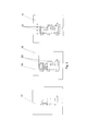
- Fig. 1 schematically a side view of a calibration and cooling device according to the invention
- Fig. 2 schematically a part of the side view on an enlarged scale
- Fig. 3 schematically a view of the first Kalibriersegments
- Fig. 4 schematic side views of different calibration segments
- Fig. 5 schematic views of various support panels
- Fig. 6 schematically a front view of the calibration and cooling device according to the invention.
- the calibration and cooling device according to Fig. 1 has a water tank 1, which has a partitioned chamber 2. In this case, the entire tank 1 is closed with a cover 3, below which there is a free space 4, which is connected to a vacuum source, not shown. As a result, there is a corresponding negative pressure in the water tank 1.
- Kalibriersegmente 6 7 are arranged, which connect to a first Kalibriersegment 5, which passes through a wall 9 of the tank 1.
- the calibration segments 6 are formed substantially identical.
- the calibration segment 7 corresponds to the calibration segments 6, but passes through the wall 8, which separates the chamber 2.
- support apertures 10, 11, 12 are arranged, wherein the support panel 12 forms the completion of the tank 1.
- the first Kalibriersegment 5 a corresponding to the desired shape of the extruded hollow profile breakthrough 13, which also made Fig. 6 can be seen.
- This breakthrough 13 is surrounded by channels 14, which lead to terminals 16 and serve as cooling channels, which are connectable to a separate cooling circuit.
- Further connections 15 connect a vacuum source with a chamber 22 surrounding the aperture 13, which is connected to the interior of the aperture 13 via slots (not shown).
- a still softer extruded strand entering the calibration segment 5 (and subsequently passing through the further calibration segments 6, 7) can be held on the inner wall of the opening 13, wherein inside the Hollow profiles of the normal air pressure prevails.
- the hollow section is also cooled and hardened. Due to the contact with the inner wall of the openings 13 of the Kalibriersegmente 5, 6, 7 caused by the cooling shrinkage of the material of the hollow profile on the inside, so that the dimensional accuracy of the outer contour of the hollow profile is maintained.
- connection fitting 17 For connection to the cooling circuit and the vacuum source a connection fitting 17 is provided.
- the calibration segment 5, as shown Fig. 4 can be seen, two lugs 18, 19, of which the projection 18 is held in the wall 9 of the tank 1 and the projection 19 serves as a centering approach, which engages in a centering of a subsequent Kalibriersegments 6, which also has one of the desired outer contour of the extruded strand corresponding breakthrough 13 has.
- 6 channels 20 are incorporated at one end faces of the Kalibriersegmente, which are in communication with the inner wall of the opening, so that the pressure prevailing in the chamber 2 negative pressure acts on the extrusion line.
- the centering lugs 19 of the calibration segments 5, 6 engage in centering recesses of the adjacent Kalibriersegmentes, whereby such a calibration unit can be easily adapted by varying the number of Kalibriersegmente 6 to the respective requirements.
- a calibration segment 7 is held in the partition 8 of the tank 1 and has no centering approach. This represents the end of a calibration unit.
- the support panels 10, 11, 12 are provided with an opening 13, whose shape corresponds to the desired contour of the hollow profile.
- bores 23 are provided, which are arranged near the opening 13 and allow a flow through the support panel 10, 11. It is the Supporting panel 10 is provided with a recess 24 which allows an overflow in this area.
- the support panel 12 closes the water tank 1 and allows the passage of the calibrated hollow profile strand.
Landscapes
- Engineering & Computer Science (AREA)
- Mechanical Engineering (AREA)
- Physics & Mathematics (AREA)
- Thermal Sciences (AREA)
- Extrusion Moulding Of Plastics Or The Like (AREA)
Abstract
Kalibrier- und Kühleinrichtung für extrudierte Kunststoff-Hohlprofile, die mehrere Kalibriersegmente (5,6,7) mit - dem gewünschten Profil entsprechenden - Durchbrüchen (13) aufweist. Zu den Innenwänden führen mit einer Unterdruckquelle in Verbindung stehende Kanäle. Den Kalibriersegmenten (5,6,7) ist ein Wassertank (1) nachgeordnet, in dem Stützblenden (10,11,12) angeordnet sind, deren Durchbrüche der Außenkontur des Hohlprofils entsprechen. Der Wassertank (1) ist abgeschlossen und weist einen Freiraum (4) auf, der mit einer Unterdruckquelle in Verbindung steht. Um einen einfachen Aufbau einer solchen Einrichtung zu ermöglichen, ist vorgesehen, dass nur dasjenige Kalibriersegment (5), welches vom zu kalibrierenden Hohlprofil zuerst durchsetzt wird, an einen eigenen Kühlkreislauf angeschlossen und mit einem eigenen Anschluss an eine Unterdruckquelle versehen ist und dass die übrigen Kalibriersegmente (6,7) im Wassertank (1) angeordnet sind.
Description
- Die Erfindung betrifft eine Kalibrier- und Kühleinrichtung nach dem Oberbegriff des Anspruchs 1.
- Mit derartigen Kalibrier- und Kühleinrichtungen werden oft relativ kompliziert geformte Hohlprofile, wie z.B. Profile zur Herstellung von Fensterrahmen, kalibriert und gekühlt. Dabei ist es erforderlich, dass die Außenkontur des Hohlprofils in engen Toleranzen gehalten wird. Dies wird durch den an der Innenwand der Durchbrüche der Kalibriersegmente herrschenden Unterdruck erreicht, der dafür sorgt, dass das noch weiche, extrudierte Hohlprofil an die Innenwand der Kalibriersegmente gepresst wird und an einem Zusammenfallen gehindert wird.
- Bei bekannten derartigen Kalibrier- und Kühleinrichtungen sind oft Trocken- und Nasskalibrierung kombiniert. Bei der Trockenkalibrierung sind mehrere Kalibriersegmente vorgesehen, die alle mit einem Kühlkreislauf verbunden sind und die an eine Unterdruckquelle angeschlossen sind. Nach dem Verlassen des letzten Kalibriersegments der Trockenkalibrierung gelangt der extrudierte Hohlprofilstrang zur Nasskalibrierung in den Wassertank.
- Der Aufbau der bekannten derartigen Kalibrier- und Kühleinrichtungen, wie sie beispielsweise in der
AT 4441 U1 - Ziel der Erfindung ist es, diesen Nachteil zu vermeiden und eine Kalibrier- und Kühleinrichtung der eingangs erwähnten Art vorzuschlagen, die sich durch einen einfacheren Aufbau auszeichnet.
- Erfindungsgemäß wird dies durch die kennzeichnenden Merkmale des Anspruchs 1 erreicht.
- Durch die vorgeschlagenen Maßnahmen ergibt sich der Vorteil, dass lediglich ein Kalibriersegment mit Kühlkanälen ausgestattet zu werden braucht. Dadurch können die übrigen Kalibriersegmente sehr einfach gestaltet werden und es entfallen aufgrund der Kühlung der Kalibriersegmente durch das Wasser des Wassertanks auch die bisher erforderlichen Verbindungen mit einem Kühlkreislauf. Es ist dies dann zwar keine reine Trockenkalibrierung mehr, aber dies stört nicht, wie im Rahmen der vorliegenden Erfindung festgestellt wurde. Es genügt die Trockenkalibrierung im ersten Segment, wo Temperatur und Unterdruck individuell eingestellt werden kann; die weiteren Segmente können alle auf der gleichen Temperatur und dem gleichen Unterdruck gehalten werden, indem sie einfach im Wassertank angeordnet sind.
- Durch die Merkmale des Anspruchs 2 ergibt sich der Vorteil, dass der Druck in der Kammer unabhängig vom übrigen Wassertank geregelt werden kann, d.h. die eigentliche Nasskalibrierung kann mit geringerem Unterdruck erfolgen, wie dies auch bisher üblich war.
- Um eine einfache Anpassung der Zahl der Kalibriersegmente an die jeweiligen Erfordernisse zu ermöglichen, ist es vorteilhaft, die Merkmale des Anspruchs 3 vorzusehen. Dabei kann je nach Bedarf die Zahl der Kalibriersegmente einfach erhöht oder vermindert werden. Die für das jeweilige Hohlprofilerforderliche Anzahl von Kalibriersegmenten kann einfach zusammengesteckt und miteinander, z.B. mittels Schrauben, verbunden werden.
- Eine in konstruktiver Hinsicht sehr einfache Lösung ergibt sich durch die Merkmale des Anspruchs 4.
- Um einen kompakten Aufbau der Kalibrier- und Kühleinrichtung sicherzustellen, können die Merkmale des Anspruchs 5 vorgesehen werden.
- Weiters können die Merkmale des Anspruchs 6 vorgesehen sein. Durch diese Maßnahmen ergibt sich der Vorteil, dass eine laminare Strömung vermieden wird und daher ein sehr guter Wärmeaustausch zwischen dem zu kühlenden Strang des Hohlprofils und dem Wasser erfolgt.
- Die Erfindung wird nun anhand der Zeichnungen näher erläutert. Dabei zeigt:
Fig. 1 schematisch eine Seitenansicht einer erfindungsgemäßen Kalibrier- und Kühleinrichtung;Fig. 2 schematisch einen Teil der Seitenansicht in vergrößertem Maßstab;Fig. 3 schematisch eine Ansicht des ersten Kalibriersegments;Fig. 4 schematisch Seitenansichten verschiedener Kalibriersegmente;Fig. 5 schematisch Ansichten verschiedener Stützblenden; undFig. 6 schematisch eine Frontansicht der erfindungsgemäßen Kalibrier- und Kühleinrichtung. - Die Kalibrier- und Kühleinrichtung gemäß
Fig. 1 weist einen Wassertank 1 auf, der eine abgeteilte Kammer 2 aufweist. Dabei ist der gesamte Tank 1 mit einem Deckel 3 abgeschlossen, unter dem sich ein Freiraum 4 befindet, der mit einer nicht dargestellten Unterdruckquelle verbunden ist. Dadurch herrscht im Wassertank 1 ein entsprechender Unterdruck. - In der Kammer 2 sind Kalibriersegmente 6, 7 angeordnet, die an ein erstes Kalibriersegment 5 anschließen, das eine Wand 9 des Tanks 1 durchsetzt. Die Kalibriersegmente 6 sind im Wesentlichen baugleich ausgebildet. Das Kalibriersegment 7 entspricht den Kalibriersegmenten 6, durchsetzt jedoch die Wand 8, die die Kammer 2 abtrennt.
- Außerhalb der Kammer 2 sind in Bewegungsrichtung eines extrudierten Hohlprofilstranges in immer größer werdenden Abständen Stützblenden 10, 11, 12 angeordnet, wobei die Stützblende 12 den Abschluss des Tanks 1 bildet.
- Wie aus
Fig. 3 zu ersehen ist, weist das erste Kalibriersegment 5 einen der gewünschten Form des extrudierten Hohlprofils entsprechenden Durchbruch 13 auf, der auch ausFig. 6 zu ersehen ist. Dieser Durchbruch 13 ist von Kanälen 14 umgeben, die zu Anschlüssen 16 führen und als Kühlkanäle dienen, die mit einem separaten Kühlkreislauf verbindbar sind. - Weitere Anschlüsse 15 verbinden eine Unterdruckquelle mit einer den Durchbruch 13 umgebenden Kammer 22, die über Schlitze (nicht dargestellt) mit dem Inneren des Durchbruchs 13 verbunden ist. Dadurch kann ein noch weicher extrudierter Strang, der in das Kalibriersegment 5 eintritt (und danach die weiteren Kalibriersegmente 6, 7 durchläuft), an der Innenwand des Durchbruchs 13 gehalten werden, wobei im Inneren des Hohlprofils der normale Luftdruck herrscht. Dabei wird das Hohlprofil auch gekühlt und erhärtet. Aufgrund der Anlage an der Innenwand der Durchbrüche 13 der Kalibriersegmente 5, 6, 7 erfolgt die durch die Abkühlung bedingte Schrumpfung des Materials des Hohlprofils an dessen Innenseite, sodass die Maßhaltigkeit der Außenkontur des Hohlprofils erhalten bleibt.
- Zum Anschluss an den Kühlkreislauf und die Unterdruckquelle ist eine Anschlussgarnitur 17 vorgesehen.
- An der äußeren Stirnseite des Kalibriersegments 5 ist dieses mit einer Abdeckung 21 abgedeckt, damit die als Nuten ausgeführten Kanäle 14, 22 geschlossen sind.
- Das Kalibriersegment 5 weist, wie aus
Fig. 4 zu ersehen ist, zwei Ansätze 18, 19 auf, von denen der Ansatz 18 in der Wand 9 des Tanks 1 gehalten ist und der Ansatz 19 als Zentrieransatz dient, der in eine Zentrierausnehmung eines anschließenden Kalibriersegments 6 eingreift, das ebenfalls einen der gewünschten Außenkontur des extrudierten Stranges entsprechenden Durchbruch 13 aufweist. Dabei sind an den einen Stirnseiten der Kalibriersegmente 6 Kanäle 20 eingearbeitet, die mit der Innenwand des Durchbruchs in Verbindung stehen, sodass der in der Kammer 2 herrschende Unterdruck auf den Extrusionsstrang wirkt. Die Zentrieransätze 19 der Kalibriersegmente 5, 6 greifen in Zentriervertiefungen des benachbarten Kalibriersegmentes ein, wodurch eine solche Kalibriereinheit sehr einfach durch Variation der Zahl der Kalibriersegmente 6 an die jeweiligen Erfordernisse angepasst werden kann. - Ein Kalibriersegment 7 ist in der Trennwand 8 des Tanks 1 gehalten und weist keinen Zentrieransatz auf. Dieses stellt das Ende einer Kalibriereinheit dar.
- Wie aus
Fig. 5 zu ersehen ist, sind die Stützblenden 10, 11, 12 mit einem Durchbruch 13 versehen, dessen Gestalt der gewünschten Kontur des Hohlprofils entspricht. Bei den Stützblenden 10 und 11 sind Bohrungen 23 vorgesehen, die nahe dem Durchbruch 13 angeordnet sind und eine Durchströmung der Stützblende 10, 11 ermöglichen. Dabei ist die Stützblende 10 mit einer Ausnehmung 24 versehen, die ein Überströmen in diesem Bereich ermöglicht. - Die Stützblende 12 schließt den Wassertank 1 ab und ermöglicht den Durchtritt des kalibrierten Hohlprofilstranges.
Claims (6)
- Kalibrier- und Kühleinrichtung für extrudierte Kunststoff-Hohlprofile, die mehrere Kalibriersegmente (5, 6, 7) aufweist, welche mit - dem gewünschten Profil entsprechenden - Durchbrüchen (13) versehen sind, zu deren Innenwänden mit einer Unterdruckquelle in Verbindung stehende Kanäle (15, 22) führen, wobei den Kalibriersegmenten (5, 6, 7) ein Wassertank (1), in dem Stützblenden (10, 11, 12) angeordnet sind, deren Durchbrüche (13) der Außenkontur des Hohlprofils entsprechen, nachgeordnet ist, der abgeschlossen ist und einen Freiraum (4) aufweist, der mit einer Unterdruckquelle in Verbindung steht, dadurch gekennzeichnet, dass nur jenes Kalibriersegment (5), welches vom zu kalibrierenden Hohlprofil zuerst durchsetzt wird, an einen eigenen Kühlkreislauf angeschlossen und mit einem eigenen Anschluss an eine Unterdruckquelle versehen ist und dass die weiteren Kalibriersegmente (6, 7) im Wassertank (1) angeordnet sind und durch das umgebende Wasser gekühlt sind.
- Kalibrier- und Kühleinrichtung nach Anspruch 1, dadurch gekennzeichnet, dass die weiteren Kalibriersegmente (6, 7) in einer Kammer (2) des Wassertanks (1) angeordnet sind, deren Unterdruck unabhängig von dem des restlichen Wassertanks einstellbar ist.
- Kalibrier- und Kühleinrichtung nach Anspruch 1 oder 2, dadurch gekennzeichnet, dass die Kalibriersegmente (5, 6) Zentrieransätze (19) bzw. entsprechende -ausnehmungen aufweisen.
- Kalibrier- und Kühleinrichtung nach einem der Ansprüche 1 bis 3, dadurch gekennzeichnet, dass die Kanäle zur Herstellung einer Verbindung mit der Unterdruckquelle bei den weiteren Kalibriersegmenten (6, 7) durch zwischen den einzelnen Kalibriersegmenten (6, 7) angeordnete Schlitze (20) gebildet sind.
- Kalibrier- und Kühleinrichtung nach einem der Ansprüche 1 bis 4, dadurch gekennzeichnet, dass das erste, mit einem eigenen Kühlkreislauf verbundene Kalibriersegment (5) dicht in einer Wand des Wassertanks (1) gehalten ist.
- Kalibrier- und Kühleinrichtung nach einem der Ansprüche 1 bis 5, dadurch gekennzeichnet, dass die Stützblenden (10, 11) mit Bohrungen (23) versehen sind, wobei die Bohrungen einander benachbarter Stützelemente (10, 11) gegeneinander versetzt angeordnet sind.
Applications Claiming Priority (1)
| Application Number | Priority Date | Filing Date | Title |
|---|---|---|---|
| AT0040910U AT12251U1 (de) | 2010-06-28 | 2010-06-28 | Kalibrier- und kühleinrichtung |
Publications (1)
| Publication Number | Publication Date |
|---|---|
| EP2399721A1 true EP2399721A1 (de) | 2011-12-28 |
Family
ID=44786940
Family Applications (1)
| Application Number | Title | Priority Date | Filing Date |
|---|---|---|---|
| EP11171620A Withdrawn EP2399721A1 (de) | 2010-06-28 | 2011-06-28 | Kalibrier- und Kühleinrichtung für Extrusionsprofile |
Country Status (2)
| Country | Link |
|---|---|
| EP (1) | EP2399721A1 (de) |
| AT (1) | AT12251U1 (de) |
Citations (8)
| Publication number | Priority date | Publication date | Assignee | Title |
|---|---|---|---|---|
| DE1911223A1 (de) * | 1969-03-05 | 1970-09-17 | Bellaplast Heller & Co Maschb | Einfuehrungsvorrichtung fuer Kunststoffrohr-Kalibratoren |
| DE2239746A1 (de) * | 1972-08-12 | 1974-02-21 | Reifenhaeuser Kg | Vorrichtung zum kalibrieren von stranggepressten profilen, insbes. hohlprofilen, aus thermoplastischem kunststoff |
| DE2239747A1 (de) * | 1972-08-12 | 1974-02-21 | Reifenhaeuser Kg | Vorrichtung zum kalibrieren von profilen, insbes. hohlprofilen aus thermoplastischem kunststoff |
| EP0925905A1 (de) * | 1997-12-22 | 1999-06-30 | Technoplast Kunststofftechnik Gesellschaft m.b.H. | Vorrichtung zum Abkühlen und Kalibrieren von extrudierten Kunststoffprofilen |
| DE19917837A1 (de) * | 1998-04-27 | 1999-10-28 | Greiner & Soehne C A | Kalibriervorrichtung mit zumindest einem Kalibrierwerkzeug |
| DE19857574A1 (de) * | 1998-12-14 | 2000-10-12 | Koemmerling Kunststoff | Vorrichtung zum Abkühlen und Kalibrieren extrudierter Kunststoffprofile |
| AT4441U1 (de) | 2001-02-14 | 2001-07-25 | Greiner Extrusionstechnik Gmbh | Kalibriervorrichtung mit zumindest einem kalibrierwerkzeug |
| US20060159794A1 (en) * | 2002-12-12 | 2006-07-20 | Meinhard Schwaiger | Method for regulating the vacuum supply of calibration tools |
-
2010
- 2010-06-28 AT AT0040910U patent/AT12251U1/de not_active IP Right Cessation
-
2011
- 2011-06-28 EP EP11171620A patent/EP2399721A1/de not_active Withdrawn
Patent Citations (8)
| Publication number | Priority date | Publication date | Assignee | Title |
|---|---|---|---|---|
| DE1911223A1 (de) * | 1969-03-05 | 1970-09-17 | Bellaplast Heller & Co Maschb | Einfuehrungsvorrichtung fuer Kunststoffrohr-Kalibratoren |
| DE2239746A1 (de) * | 1972-08-12 | 1974-02-21 | Reifenhaeuser Kg | Vorrichtung zum kalibrieren von stranggepressten profilen, insbes. hohlprofilen, aus thermoplastischem kunststoff |
| DE2239747A1 (de) * | 1972-08-12 | 1974-02-21 | Reifenhaeuser Kg | Vorrichtung zum kalibrieren von profilen, insbes. hohlprofilen aus thermoplastischem kunststoff |
| EP0925905A1 (de) * | 1997-12-22 | 1999-06-30 | Technoplast Kunststofftechnik Gesellschaft m.b.H. | Vorrichtung zum Abkühlen und Kalibrieren von extrudierten Kunststoffprofilen |
| DE19917837A1 (de) * | 1998-04-27 | 1999-10-28 | Greiner & Soehne C A | Kalibriervorrichtung mit zumindest einem Kalibrierwerkzeug |
| DE19857574A1 (de) * | 1998-12-14 | 2000-10-12 | Koemmerling Kunststoff | Vorrichtung zum Abkühlen und Kalibrieren extrudierter Kunststoffprofile |
| AT4441U1 (de) | 2001-02-14 | 2001-07-25 | Greiner Extrusionstechnik Gmbh | Kalibriervorrichtung mit zumindest einem kalibrierwerkzeug |
| US20060159794A1 (en) * | 2002-12-12 | 2006-07-20 | Meinhard Schwaiger | Method for regulating the vacuum supply of calibration tools |
Also Published As
| Publication number | Publication date |
|---|---|
| AT12251U1 (de) | 2012-02-15 |
Similar Documents
| Publication | Publication Date | Title |
|---|---|---|
| DE2344658A1 (de) | Vorrichtung zum dimensionieren von extrudierten kunststoffgegenstaenden | |
| DE10112736B4 (de) | Heizwalze für eine Heizeinrichtung zum Erwärmen einer Folienbahn aus thermoplastischem Kunststoff | |
| DE1504253C3 (de) | Längsspritzkopf mit Dorn zum Herstellen von Hohlprofilen | |
| AT412770B (de) | Formgebungseinrichtung für eine extrusionsanlage | |
| DE1657315A1 (de) | Verbesserte Plattenelektrode-Einheit fuer eine elektrostatische Niederschlagsvorrichtung | |
| DE202010003895U1 (de) | Werkzeugkomponente für ein Blasformwerkzeug | |
| DE19941160B4 (de) | Zylinder für einen Schneckenextruder mit Kanälen für ein Temperiermedium | |
| DE4016368A1 (de) | Spruehkopf einer spruehvorrichtung zum aufspruehen von fluessigkeiten, insbesondere trennmitteln | |
| EP2399721A1 (de) | Kalibrier- und Kühleinrichtung für Extrusionsprofile | |
| DE2341323C2 (de) | Schalttafel für Fahrzeuge, insbesondere Kraftfahrzeuge | |
| DE102007011042B4 (de) | Verfahren zum Herstellen eines Sprühbalkens, Sprühbalken und Druckmaschine mit Sprühbalken | |
| WO2015051936A1 (de) | Vorrichtung zum anschluss von sanitärarmaturen | |
| WO2004011227A1 (de) | Wassrestandsregelung für die kühleinrichtung einer extrusionsanlage | |
| AT413966B (de) | Kühlvorrichtung für strangpressprofile | |
| DE19903699A1 (de) | Formwerkzeug | |
| AT410299B (de) | Vorrichtung zum kühlen und kalibrieren eines extrudierten kunststoffprofils | |
| EP1884723A1 (de) | Baueinheit | |
| AT507720A1 (de) | Kalibrierblock für extrusionsvorrichtung | |
| DE1779993C3 (de) | Formmaschine zur Verarbeitung von aufschäumbaren Kunststoffen. Ausscheidung aus: 1504592 | |
| DE29902820U1 (de) | Temperierbare Walze, insbesondere heizbare Kalanderwalze | |
| DE2125742C3 (de) | Formkasten zur Formung eines Formkörpers aus thermoplastischen expandierfähigen Teilchen | |
| DE102012215851A1 (de) | Vorrichtung zum Bereitstellen einer elektrischen oder fluiden Anschlussstelle | |
| EP2735810B1 (de) | Luftauslass | |
| EP1867459B1 (de) | Vorrichtung zum Kalibrieren und Kühlen von Kunststoffprofilen | |
| DE10237730B4 (de) | Vorrichtung zum Kalibrieren von Kunststoffprofilen |
Legal Events
| Date | Code | Title | Description |
|---|---|---|---|
| AK | Designated contracting states |
Kind code of ref document: A1 Designated state(s): AL AT BE BG CH CY CZ DE DK EE ES FI FR GB GR HR HU IE IS IT LI LT LU LV MC MK MT NL NO PL PT RO RS SE SI SK SM TR |
|
| AX | Request for extension of the european patent |
Extension state: BA ME |
|
| PUAI | Public reference made under article 153(3) epc to a published international application that has entered the european phase |
Free format text: ORIGINAL CODE: 0009012 |
|
| STAA | Information on the status of an ep patent application or granted ep patent |
Free format text: STATUS: THE APPLICATION IS DEEMED TO BE WITHDRAWN |
|
| 18D | Application deemed to be withdrawn |
Effective date: 20120629 |