EP2399748B1 - Cartouche d'encre pour imprimante à jet d'encre - Google Patents
Cartouche d'encre pour imprimante à jet d'encre Download PDFInfo
- Publication number
- EP2399748B1 EP2399748B1 EP09840250.6A EP09840250A EP2399748B1 EP 2399748 B1 EP2399748 B1 EP 2399748B1 EP 09840250 A EP09840250 A EP 09840250A EP 2399748 B1 EP2399748 B1 EP 2399748B1
- Authority
- EP
- European Patent Office
- Prior art keywords
- ink
- cartridge
- jet printer
- sensor
- cartridge body
- Prior art date
- Legal status (The legal status is an assumption and is not a legal conclusion. Google has not performed a legal analysis and makes no representation as to the accuracy of the status listed.)
- Not-in-force
Links
- 230000001681 protective effect Effects 0.000 claims description 16
- 230000005484 gravity Effects 0.000 claims description 10
- 238000000034 method Methods 0.000 claims description 6
- 230000008569 process Effects 0.000 claims description 6
- 238000001514 detection method Methods 0.000 description 24
- 238000010586 diagram Methods 0.000 description 11
- 230000007246 mechanism Effects 0.000 description 11
- 238000009434 installation Methods 0.000 description 10
- 238000004519 manufacturing process Methods 0.000 description 7
- 239000000463 material Substances 0.000 description 4
- 239000003570 air Substances 0.000 description 3
- 230000008859 change Effects 0.000 description 3
- 230000005540 biological transmission Effects 0.000 description 2
- 239000012080 ambient air Substances 0.000 description 1
- 230000008901 benefit Effects 0.000 description 1
- 230000007547 defect Effects 0.000 description 1
- 230000001419 dependent effect Effects 0.000 description 1
- 238000011900 installation process Methods 0.000 description 1
- 238000000465 moulding Methods 0.000 description 1
- 230000003287 optical effect Effects 0.000 description 1
- 230000001737 promoting effect Effects 0.000 description 1
- 230000001012 protector Effects 0.000 description 1
- 230000009467 reduction Effects 0.000 description 1
- 230000004044 response Effects 0.000 description 1
Images


Classifications
-
- B—PERFORMING OPERATIONS; TRANSPORTING
- B41—PRINTING; LINING MACHINES; TYPEWRITERS; STAMPS
- B41J—TYPEWRITERS; SELECTIVE PRINTING MECHANISMS, i.e. MECHANISMS PRINTING OTHERWISE THAN FROM A FORME; CORRECTION OF TYPOGRAPHICAL ERRORS
- B41J2/00—Typewriters or selective printing mechanisms characterised by the printing or marking process for which they are designed
- B41J2/005—Typewriters or selective printing mechanisms characterised by the printing or marking process for which they are designed characterised by bringing liquid or particles selectively into contact with a printing material
- B41J2/01—Ink jet
- B41J2/17—Ink jet characterised by ink handling
- B41J2/175—Ink supply systems ; Circuit parts therefor
- B41J2/17566—Ink level or ink residue control
-
- B—PERFORMING OPERATIONS; TRANSPORTING
- B41—PRINTING; LINING MACHINES; TYPEWRITERS; STAMPS
- B41J—TYPEWRITERS; SELECTIVE PRINTING MECHANISMS, i.e. MECHANISMS PRINTING OTHERWISE THAN FROM A FORME; CORRECTION OF TYPOGRAPHICAL ERRORS
- B41J2/00—Typewriters or selective printing mechanisms characterised by the printing or marking process for which they are designed
- B41J2/005—Typewriters or selective printing mechanisms characterised by the printing or marking process for which they are designed characterised by bringing liquid or particles selectively into contact with a printing material
- B41J2/01—Ink jet
- B41J2/17—Ink jet characterised by ink handling
- B41J2/175—Ink supply systems ; Circuit parts therefor
- B41J2/17503—Ink cartridges
- B41J2/17513—Inner structure
-
- B—PERFORMING OPERATIONS; TRANSPORTING
- B41—PRINTING; LINING MACHINES; TYPEWRITERS; STAMPS
- B41J—TYPEWRITERS; SELECTIVE PRINTING MECHANISMS, i.e. MECHANISMS PRINTING OTHERWISE THAN FROM A FORME; CORRECTION OF TYPOGRAPHICAL ERRORS
- B41J2/00—Typewriters or selective printing mechanisms characterised by the printing or marking process for which they are designed
- B41J2/005—Typewriters or selective printing mechanisms characterised by the printing or marking process for which they are designed characterised by bringing liquid or particles selectively into contact with a printing material
- B41J2/01—Ink jet
- B41J2/17—Ink jet characterised by ink handling
- B41J2/175—Ink supply systems ; Circuit parts therefor
- B41J2/17566—Ink level or ink residue control
- B41J2002/17573—Ink level or ink residue control using optical means for ink level indication
Definitions
- the invention relates to cartridges for ink-jet printers.
- Cartridges of the preamble part of claim 1 are known from EP 1 772 274 A2 .
- US 4,604,633 relates to an ink-jet recording apparatus having a detecting means for detecting an ink-pressure or an ink-residual quantity disposed to a part of an ink-supply system for supplying ink from an ink-reservoir.
- the upper part of a common ink chamber of the recording head has an opening which is attached with and is covered by a flexible diaphragm to form a flexible upper wall of the common ink.
- a rotation supporting shaft is provided to the upper part of a regulator frame.
- An arm is made freely swingable. A part of the arm has a connector which is attached to the flexible diaphragm.
- a light shielding plate is fixed to the tip of the arm. In the neighborhood of the light shielding plate, there is fixed a photodetector with a light emitting element and a light receiving element. The light shielding plate is so arranged as to shield the optical path of the photodetector.
- WO 2005/000684 A2 relates to an inkjet recording apparatus which includes an apparatus main body, a paper feed tray and a paper delivery tray. At one side of a front portion of the apparatus, a cartridge load unit of the apparatus is provided. The cartridge load unit allows to remove ink cartridges.
- the apparatus main body includes a carriage that includes four recording heads, each corresponding to an ink jet head.
- the carriage also includes a sub tank for each color for supplying ink to the recording head. Ink may be supplied to the sub tanks from the ink cartridges via an ink supply tube.
- the sub tank includes a container main body that forms an ink accommodating portion and a flexible film member that seals the opening of the ink accommodating member. A negative pressure lever is forced toward the film member by a spring.
- Detection electrodes are placed on the upper side of the container main body for detecting whether the amount of gas within the sub tank has reached a predetermined level based on a conduction change between the detection electrodes.
- a full tank detection sensor may be placed at the end portion of the negative pressure lever. Supplying of ink may be performed until the electrodes detect that the sub tank has reached its full capacity.
- EP 1 772 274 A2 discloses an ink cartridge to be mounted in an ink jet recording system.
- a colored ink cartridge is equipped with a case, which covers roughly.the entire body of ink reservoir element, and a protector, which is attached to this case and protects ink reservoir element, when the ink cartridge is fed.
- An ink reservoir element is primarily equipped with a frame part, which forms an ink reservoir chamber, an ink supply part, an ambient air intake part, a detection part and a film, which is welded to both sides of the frame part.
- a detection part projects outward from the frame part.
- the detection part is equipped with an enclosure part, which encloses the end of an sensor arm by sandwiching it with a pair of wall surfaces and forms a passage through which the sensor arm can be displaced.
- the sensor arm rotates according to the amount of remaining ink inside the ink reservoir chamber.
- the sensor arm is primarily equipped with a balance part, which is formed from a material with a lower specific gravity than that of the ink.
- An arm part is used as a light-blocking part that blocks the range of possible detection of remaining an ink detection sensor.
- the multifunction device may comprise an ink cartridge attachment detection sensor. When the ink cartridge has been attached to the correct attachment position, the edge of the case protruding parts will press a protruding piece of the ink cartridge attachment detection sensor and the ink cartridge attachment detection sensor will send a signal to the control board.
- Existing cartridges for ink-jet printers include a cartridge body, a protective cover moving relatively to the cartridge body under pressure, a detection mechanism for cartridge and remaining ink volume, wherein the cartridge body includes an ink storage chamber, an ink outlet for providing ink to the printing head and an air inlet.
- the cartridge must include two kinds of detection mechanism in order to ensure the normal operation of cartridge after installed in the printer.
- one detection mechanism at first prevents the light from the emission member of the second sensor from returning to the reception member of the second sensor, and then allows such light to return to the reception member of the second sensor with the installation progress.
- the other detection mechanism prevents the light from the emission member of the first sensor from returning to the reception member of the first sensor, and finally, the light from the emission member of the first and second sensors is prevented from returning to corresponding reception member.
- Installation detection is completed after that, and then the printer gives a prompt that cartridge installation is completed to go to the next operation.
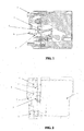
- the mechanism of the existing cartridge for detecting cartridge and ink volume is shown as FIG. 1 , comprising the first detecting member a, the second detecting member b, the third detecting member c, a light transmission member d and a movable lever e.
- the said detection mechanism is realized by shielding the light from sensor, whereof the operating principle is as follows: when cartridge is installed in the printer, the light from the second sensor in the printer is shielded by the second detecting member b initially and then connected without the shield of the second detecting member b with the installation of cartridge. After that, the light from the first sensor is shielded by the first detecting member a, and finally the light from the second sensor is also shielded by the third detecting member c, whereafter the printer gives a prompt of the existence of cartridge for the next operation.
- the said third detecting member c is comprised of a light transmission member d and a non-transparent movable lever e, the position of the latter may vary with the ink volume in the cartridge, and the light from the second sensor can detect the ink volume in the cartridge according to the fact whether the light is shielded by the third detecting member c.
- the prior-art solution involves too many detecting members and the processes are too complex in terms of installation detection of the printer.
- the defect is the design of lever.
- Complex processes of float installation reduce the production efficiency of the cartridge.
- the material for the light-shielding member moving with the change of ink volume in the cartridge must be non-transparent, while black PP material is used in the above project, so it is required to mix the black color with PP material uniformly during molding production, otherwise identification will not be performed accurately for installation of cartridge into the printer.
- the light-shielding member has to move with the change of the ink volume in the cartridge, which requires many members, resulting in complex production processes and inferior identification accuracy.
- An advantage of this invention is a simplified production process.
- the invention may comprise the following elements:
- a cartridge for ink-jet printer comprising a cartridge body, a protective cover moving relatively to the cartridge body under pressure and a detection mechanism for cartridge and remaining ink volume, the said cartridge body including an ink storage chamber, an ink outlet for providing ink to the printing head and an air inlet, characterized in that the said detection mechanism of cartridge and remaining ink volume includes the first and second detecting members respectively matching to the first and second sensors of the printer, and a soft support cap set on the cartridge body and connecting to the ink storage chamber, the said second detecting member includes a movable lever, a fixed shaft set on the cartridge body, and a position adjustment member for the movable lever set on the protective cover, of which the said movable lever is connected with the rotating shaft of the cartridge body through the fixed shaft, the position adjustment member of the movable lever can be connected to the under-part of the movable lever under gravity, and the said soft support cap is located at the position corresponding to dropping position of the movable lever under gravity so as to be connected with the movable lever when the position
- the said position adjustment member of movable lever is a draw hook.
- a sealed ink bag is installed in the said ink chamber, the sealed ink bag is connected with the said support cap.
- the detection mechanism for cartridge and remaining ink volume includes the first and second detecting members respectively matching to the first and second sensors on the printer, and a soft support cap set on the cartridge body and connecting to the ink storage chamber, wherein the said second detecting member includes a movable lever, a fixed shaft set on the cartridge body, and a position adjustment member for the movable lever set on the protective cover, of which the said movable lever is connected with the rotating shaft of the cartridge body through the fixed shaft, the position adjustment member of the movable lever can be connected to the under-part of the movable lever under the gravity of movable member, and the said soft support cap is located at the position corresponding to dropping position of the movable lever under gravity so as to be connected with the movable lever when the position adjustment member of the movable lever is above the soft support cap.
- the said second detecting member includes a movable lever, a fixed shaft set on the cartridge body, and a position adjustment member for the movable lever set on the protective cover, of which the said movable
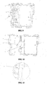
- FIGs. 2 and 10 show a cartridge for ink-jet printer, comprising a cartridge body 1, a protective cover 2 moving relatively to the cartridge body 1 under pressure and a detection mechanism for cartridge and remaining ink volume, wherein the cartridge body 1 includes an ink storage chamber, an ink outlet for providing ink to the printing head and an air inlet, and the detection mechanism for cartridge and remaining ink volume includes the first detecting member 4 and the second detecting member respectively matching to the first sensor 3 and second sensor 5 on the printer as well as a soft support cap 9 set on the cartridge body 1 and connecting to the ink storage chamber.
- the said second detecting member includes a movable lever 7, a fixed shaft 6 set on the cartridge body 1, and a position adjustment member for the movable lever 7 set on the protective cover 2, wherein the said movable lever 7 is connected with the rotating shaft of the cartridge body through the fixed shaft 6.
- the position adjustment member of the movable lever 7 can be connected to the under-part of the movable lever 7 under the gravity of the movable lever 7, and the said soft support cap 9 is located at the position corresponding to the dropping position of the movable lever 7 under its gravity so as to be connected with the movable lever 7 when the position adjustment member of the movable lever 7 is above the soft support cap 9.
- the position adjustment member of movable lever 7 is a draw hook 8.
- a sealed ink bag is set in the ink storage chamber, connecting with the soft support cap 9.
- both sensors in the printer are under the status of connection shown as FIG. 3 .
- the protective cover 2 at the front end of the cartridge is not moved while the second sensor 5 is started to be connected to the second detecting member, resulting in emission of light from the emission member of the second sensor 5, which can not return to the reception member of the second sensor 5 due to the shield of the movable lever 7 of the second detecting member.
- the light path of the second sensor 5 is disconnected while the first sensor 3 is in connection without contacting the first detecting member 4 shown as FIG. 4 .
- the movable lever 7 goes through the detecting member of the second sensor 5, resulting in the first sensor 3 being shielded by the first detecting member 4 to be in disconnection while the second sensor 5 being not shielded by the movable lever 7 to be in connection shown as FIG. 5 .
- the protective cover 2 at the front end of the cartridge moves in the opposite direction of the cartridge 1.
- the draw hook 8 fixing on the protective cover 2 moves backward and don't support the movable lever anymore, which sags down under gravity.
- one end of the movable lever 7 of the second detecting member reaches the response position of the second sensor 5 then supported by the soft support cap 9, shielding the light from the second sensor 5 again.
- the second sensor 5 is in disconnection shown as FIG. 6 and 7 .
- the light from the first sensor 3 is shielded by the first detecting member 4, making the first sensor 3 in disconnection.
- the cartridge of the printer is now available.
- the printer When there's enough ink in the cartridge, put the cartridge in the printer for printing.
- the light from the emission member is prevented by one end of the second detecting member from reaching the light reception member of printer, according to which the printer identifies that there's enough ink in the cartridge.
- the soft support cap 9 connecting to it sags down due to the emptying of the ink bag with the reduction of ink under the suck of the ink-providing needle in the printer.
- the movable lever 7 of the second detecting member continues moving under gravity to leave the position shielding the light path of the second sensor 5.
- the printer gives a prompt for running out of ink and then a signal for changing the cartridge.
- the invention realizes the functions of both original detecting members by using the second detecting member of the cartridge. In terms of manufacturing, it is featured in simple processes, easy control and reduced cost. In addition, it uses an ink storage bag to increase ink capacity, reducing user's printing cost.
Landscapes
- Ink Jet (AREA)
Claims (3)
- Cartouche pour une imprimante à jet d'encre comprenant :un corps de cartouche (1) ;un premier élément de détection (4) ressortant dudit corps de cartouche (1) ;ledit premier élément de détection (4) étant conçu de façon adaptée pour interagir avec un premier capteur (3) de ladite imprimante à jet d'encre pour détecter si ladite cartouche est installée dans ladite imprimante à jet d'encre ;un second élément de détection pour détecter l'épuisement de l'encre, ledit second élément de détection comprenant une tige (6) fixée sur ledit corps de cartouche (1) et un levier (7) pouvant pivoter autour de ladite tige (6) ; ledit levier (7) étant conçu de façon adaptée pour interagir avec un second capteur (5) de ladite imprimante à jet d'encre ;ledit corps de cartouche (1) comprenant une chambre de stockage d'encre ;caractérisée en ce que ladite cartouche comprend en outre :un cache protecteur (2) mobile par rapport audit corps de cartouche (1) ; ladite imprimante à jet d'encre, ledit cache protecteur (2) et ledit corps de cartouche (1) étant conçus pour déplacer ledit cache protecteur (2) en direction dudit corps de cartouche (1) pendant un processus de montage de ladite cartouche dans ladite imprimante à jet d'encre ;un calot de maintien mou (9) placé sur ledit corps de cartouche (1) et relié à ladite chambre de stockage d'encre ; etun élément de réglage de position (8) placé sur ledit cache protecteur (2) ; si ladite cartouche est orientée dans sa position de montage, la gravité fait pivoter une partie inférieure dudit levier (7) en direction dudit élément de réglage de position (8) et dudit calot de maintien mou (9) ; si ladite cartouche est orientée dans sa position de démontage hors de l'imprimante à jet d'encre,ledit levier (7) est maintenu par ledit élément de réglage de position (8) ;si ledit cache protecteur (2) est dans une position la plus près possible dudit corps de cartouche (1) et si ladite cartouche est orientée dans sa position de montage, ledit élément de réglage de position (8) est placé au-dessus dudit calot de maintien mou (9) et ledit calot de maintien mou (9) maintient ledit levier (7).
- Cartouche pour imprimante à jet d'encre selon la revendication 1, dans laquelle ledit élément de réglage de position de levier mobile (7) est un crochet de traction (8).
- Cartouche pour imprimante à jet d'encre selon la revendication 1, dans laquelle un sac d'encre scellé est installé dans ladite chambre d'encre, ledit sac d'encre scellé étant relié audit calot de maintien (9).
Applications Claiming Priority (2)
| Application Number | Priority Date | Filing Date | Title |
|---|---|---|---|
| CN2009101056198A CN101491975B (zh) | 2009-02-20 | 2009-02-20 | 一种用于喷墨打印机的墨盒 |
| PCT/CN2009/075192 WO2010094199A1 (fr) | 2009-02-20 | 2009-11-28 | Cartouche d'encre pour imprimante à jet d'encre |
Publications (3)
| Publication Number | Publication Date |
|---|---|
| EP2399748A1 EP2399748A1 (fr) | 2011-12-28 |
| EP2399748A4 EP2399748A4 (fr) | 2013-05-01 |
| EP2399748B1 true EP2399748B1 (fr) | 2015-06-24 |
Family
ID=40922842
Family Applications (1)
| Application Number | Title | Priority Date | Filing Date |
|---|---|---|---|
| EP09840250.6A Not-in-force EP2399748B1 (fr) | 2009-02-20 | 2009-11-28 | Cartouche d'encre pour imprimante à jet d'encre |
Country Status (5)
| Country | Link |
|---|---|
| US (1) | US8419174B2 (fr) |
| EP (1) | EP2399748B1 (fr) |
| JP (1) | JP3156861U (fr) |
| CN (1) | CN101491975B (fr) |
| WO (1) | WO2010094199A1 (fr) |
Families Citing this family (23)
| Publication number | Priority date | Publication date | Assignee | Title |
|---|---|---|---|---|
| CN101462410B (zh) * | 2008-12-31 | 2011-11-02 | 珠海纳思达电子科技有限公司 | 一种用于喷墨打印机的墨盒 |
| CN101491975B (zh) * | 2009-02-20 | 2011-12-28 | 珠海纳思达电子科技有限公司 | 一种用于喷墨打印机的墨盒 |
| CN101693424B (zh) * | 2009-10-30 | 2012-07-18 | 珠海纳思达电子科技有限公司 | 一种喷墨打印机的墨盒 |
| CN201552809U (zh) * | 2009-11-09 | 2010-08-18 | 珠海纳思达电子科技有限公司 | 一种喷墨打印机的墨盒 |
| JP5634088B2 (ja) * | 2010-03-17 | 2014-12-03 | キヤノン株式会社 | インクジェット記録装置およびインクタンク |
| CN102218924B (zh) * | 2010-04-16 | 2015-01-07 | 珠海纳思达企业管理有限公司 | 一种用于喷墨打印机的墨盒 |
| CN104608498B (zh) * | 2010-05-01 | 2017-05-31 | 珠海纳思达企业管理有限公司 | 墨盒、墨盒组以及墨盒确定系统 |
| CN102233737B (zh) * | 2010-05-01 | 2015-04-08 | 珠海纳思达企业管理有限公司 | 墨盒、墨盒组以及墨盒确定系统 |
| CN201784254U (zh) * | 2010-09-06 | 2011-04-06 | 珠海纳思达企业管理有限公司 | 一种用于墨盒的适配器及包含该适配器的墨水供应系统 |
| GB2492276B (en) * | 2010-11-22 | 2017-08-30 | Zhuhai Ninestar Man Co Ltd | Ink cartridge for inkjet printer |
| US8434859B2 (en) * | 2010-12-22 | 2013-05-07 | Seiko Epson Corporation | Cartridge |
| USD658713S1 (en) | 2010-12-24 | 2012-05-01 | Engage Technologies Corp. | Industrial printer cartridge |
| USD674008S1 (en) | 2010-12-24 | 2013-01-08 | Engage Technologies Corporation | Industrial printer |
| JP2013049168A (ja) | 2011-08-30 | 2013-03-14 | Brother Industries Ltd | 印刷流体カートリッジ及び記録装置 |
| JP6756138B2 (ja) | 2016-03-31 | 2020-09-16 | ブラザー工業株式会社 | 液体カートリッジ及びシステム |
| JP6677051B2 (ja) | 2016-03-31 | 2020-04-08 | ブラザー工業株式会社 | 液体カートリッジ |
| JP6668891B2 (ja) * | 2016-03-31 | 2020-03-18 | ブラザー工業株式会社 | 液体カートリッジ |
| JP6756137B2 (ja) | 2016-03-31 | 2020-09-16 | ブラザー工業株式会社 | 液体カートリッジ |
| JP6852272B2 (ja) * | 2016-03-31 | 2021-03-31 | ブラザー工業株式会社 | 液体カートリッジ |
| CN107878030B (zh) * | 2016-09-29 | 2020-03-24 | 兄弟工业株式会社 | 液体盒 |
| CN113710496A (zh) * | 2019-04-29 | 2021-11-26 | 惠普发展公司, 有限责任合伙企业 | 具有传感器的旋转壳体 |
| CN113022144A (zh) * | 2021-03-05 | 2021-06-25 | 珠海益捷科技有限公司 | 墨盒 |
| WO2022184072A1 (fr) * | 2021-03-05 | 2022-09-09 | 珠海瑧挚科技有限公司 | Cartouche d'encre |
Family Cites Families (16)
| Publication number | Priority date | Publication date | Assignee | Title |
|---|---|---|---|---|
| JPS59115858A (ja) * | 1982-12-23 | 1984-07-04 | Konishiroku Photo Ind Co Ltd | インクジエツト記録装置 |
| JPS59192573A (ja) * | 1983-04-18 | 1984-10-31 | Ricoh Co Ltd | インクカ−トリツジの残量検知装置 |
| JPS63207652A (ja) * | 1987-02-25 | 1988-08-29 | Seiko Epson Corp | インク残量検出装置 |
| JP3582592B2 (ja) * | 2001-04-03 | 2004-10-27 | セイコーエプソン株式会社 | インクカートリッジ、及びインクジェット記録装置 |
| US5764260A (en) * | 1996-03-14 | 1998-06-09 | Jetfill, Inc. | Reusable inkjet cartridge adaptor |
| US6454400B1 (en) * | 1998-09-01 | 2002-09-24 | Canon Kabushiki Kaisha | Liquid container, cartridge including liquid container, printing apparatus using cartridge and liquid discharge printing apparatus |
| US6976749B2 (en) * | 2002-03-28 | 2005-12-20 | Brother Kogyo Kabushiki Kaisha | Ink cartridge and recording device |
| KR100790431B1 (ko) * | 2003-06-25 | 2008-01-02 | 가부시키가이샤 리코 | 액체 컨테이너, 서브 탱크, 액체 방출 장치, 액체 공급장치 및 이미징 장치 |
| MXPA04012988A (es) * | 2003-12-22 | 2005-10-18 | Seiko Epson Corp | Aparato para montar/desmontar un cartucho de tinta, aparato de registro, aparato para expulsion de liquidos y contenedor de liquidos. |
| CN100404268C (zh) * | 2004-10-20 | 2008-07-23 | 佳能株式会社 | 液体容器以及供墨系统 |
| KR100694149B1 (ko) * | 2005-08-05 | 2007-03-12 | 삼성전자주식회사 | 잉크레벨 검지장치 및 이를 구비한 잉크젯 화상형성장치 |
| CN2832527Y (zh) * | 2005-08-30 | 2006-11-01 | 珠海纳思达电子科技有限公司 | 一种分体式发光墨盒 |
| ATE404376T1 (de) * | 2005-09-29 | 2008-08-15 | Brother Ind Ltd | Tintenpatrone, satz von tintenpatronen und tintenstrahlaufzeichnungssystem |
| JP4739079B2 (ja) * | 2006-03-30 | 2011-08-03 | 株式会社セイコーアイ・インフォテック | インクカートリッジ及び記録装置 |
| JP4591466B2 (ja) * | 2007-03-28 | 2010-12-01 | ブラザー工業株式会社 | インクカートリッジ及びインクカートリッジ収容体 |
| CN101491975B (zh) * | 2009-02-20 | 2011-12-28 | 珠海纳思达电子科技有限公司 | 一种用于喷墨打印机的墨盒 |
-
2009
- 2009-02-20 CN CN2009101056198A patent/CN101491975B/zh active Active
- 2009-11-05 JP JP2009007876U patent/JP3156861U/ja not_active Expired - Lifetime
- 2009-11-28 WO PCT/CN2009/075192 patent/WO2010094199A1/fr not_active Ceased
- 2009-11-28 EP EP09840250.6A patent/EP2399748B1/fr not_active Not-in-force
- 2009-11-28 US US12/988,545 patent/US8419174B2/en not_active Expired - Fee Related
Also Published As
| Publication number | Publication date |
|---|---|
| JP3156861U (ja) | 2010-01-21 |
| CN101491975B (zh) | 2011-12-28 |
| US20110292138A1 (en) | 2011-12-01 |
| US8419174B2 (en) | 2013-04-16 |
| EP2399748A4 (fr) | 2013-05-01 |
| EP2399748A1 (fr) | 2011-12-28 |
| CN101491975A (zh) | 2009-07-29 |
| WO2010094199A1 (fr) | 2010-08-26 |
Similar Documents
| Publication | Publication Date | Title |
|---|---|---|
| EP2399748B1 (fr) | Cartouche d'encre pour imprimante à jet d'encre | |
| CN105235392B (zh) | 墨容纳装置 | |
| JP4380712B2 (ja) | 液滴吐出装置 | |
| JP6794783B2 (ja) | 液体噴射装置 | |
| CN103358706B (zh) | 墨容纳装置和适配器 | |
| EP3300899B1 (fr) | Dispositif contenant du liquide d'impression comprenant une cartouche de liquide d'impression et un adaptateur et système associé | |
| CN100551706C (zh) | 墨盒和一组墨盒 | |
| EP3208094B1 (fr) | Système de détermination et cartouche de fluide d'impression | |
| CN107878035B (zh) | 液体盒和液体消耗装置 | |
| US20210370679A1 (en) | System | |
| TW200930576A (en) | Liquid container and liquid injection device | |
| JP6878885B2 (ja) | インクジェット記録装置 | |
| JP7616285B2 (ja) | 画像記録装置 | |
| US10926545B2 (en) | Liquid supplying system including cartridge and tank having air communication port covered with semipermeable membrane | |
| CN111902289B (zh) | 图像记录设备 | |
| US11014371B2 (en) | Image recording apparatus | |
| JP7687492B2 (ja) | システム | |
| JP7749964B2 (ja) | 液体吐出装置及び液体貯留器 | |
| JP7673780B2 (ja) | 液体供給装置及び画像記録装置 | |
| JP4923932B2 (ja) | 検出装置 | |
| JP2020111035A (ja) | システム | |
| JP2019177498A (ja) | 液体消費システム |
Legal Events
| Date | Code | Title | Description |
|---|---|---|---|
| PUAI | Public reference made under article 153(3) epc to a published international application that has entered the european phase |
Free format text: ORIGINAL CODE: 0009012 |
|
| 17P | Request for examination filed |
Effective date: 20110905 |
|
| AK | Designated contracting states |
Kind code of ref document: A1 Designated state(s): AT BE BG CH CY CZ DE DK EE ES FI FR GB GR HR HU IE IS IT LI LT LU LV MC MK MT NL NO PL PT RO SE SI SK SM TR |
|
| DAX | Request for extension of the european patent (deleted) | ||
| A4 | Supplementary search report drawn up and despatched |
Effective date: 20130403 |
|
| RIC1 | Information provided on ipc code assigned before grant |
Ipc: B41J 2/175 20060101AFI20130326BHEP |
|
| GRAP | Despatch of communication of intention to grant a patent |
Free format text: ORIGINAL CODE: EPIDOSNIGR1 |
|
| INTG | Intention to grant announced |
Effective date: 20150105 |
|
| GRAS | Grant fee paid |
Free format text: ORIGINAL CODE: EPIDOSNIGR3 |
|
| GRAA | (expected) grant |
Free format text: ORIGINAL CODE: 0009210 |
|
| AK | Designated contracting states |
Kind code of ref document: B1 Designated state(s): AT BE BG CH CY CZ DE DK EE ES FI FR GB GR HR HU IE IS IT LI LT LU LV MC MK MT NL NO PL PT RO SE SI SK SM TR |
|
| REG | Reference to a national code |
Ref country code: GB Ref legal event code: FG4D |
|
| REG | Reference to a national code |
Ref country code: CH Ref legal event code: EP |
|
| REG | Reference to a national code |
Ref country code: AT Ref legal event code: REF Ref document number: 732721 Country of ref document: AT Kind code of ref document: T Effective date: 20150715 |
|
| REG | Reference to a national code |
Ref country code: IE Ref legal event code: FG4D |
|
| REG | Reference to a national code |
Ref country code: DE Ref legal event code: R096 Ref document number: 602009031894 Country of ref document: DE |
|
| PG25 | Lapsed in a contracting state [announced via postgrant information from national office to epo] |
Ref country code: HR Free format text: LAPSE BECAUSE OF FAILURE TO SUBMIT A TRANSLATION OF THE DESCRIPTION OR TO PAY THE FEE WITHIN THE PRESCRIBED TIME-LIMIT Effective date: 20150624 Ref country code: FI Free format text: LAPSE BECAUSE OF FAILURE TO SUBMIT A TRANSLATION OF THE DESCRIPTION OR TO PAY THE FEE WITHIN THE PRESCRIBED TIME-LIMIT Effective date: 20150624 Ref country code: LT Free format text: LAPSE BECAUSE OF FAILURE TO SUBMIT A TRANSLATION OF THE DESCRIPTION OR TO PAY THE FEE WITHIN THE PRESCRIBED TIME-LIMIT Effective date: 20150624 Ref country code: NO Free format text: LAPSE BECAUSE OF FAILURE TO SUBMIT A TRANSLATION OF THE DESCRIPTION OR TO PAY THE FEE WITHIN THE PRESCRIBED TIME-LIMIT Effective date: 20150924 |
|
| REG | Reference to a national code |
Ref country code: AT Ref legal event code: MK05 Ref document number: 732721 Country of ref document: AT Kind code of ref document: T Effective date: 20150624 |
|
| REG | Reference to a national code |
Ref country code: LT Ref legal event code: MG4D |
|
| PG25 | Lapsed in a contracting state [announced via postgrant information from national office to epo] |
Ref country code: GR Free format text: LAPSE BECAUSE OF FAILURE TO SUBMIT A TRANSLATION OF THE DESCRIPTION OR TO PAY THE FEE WITHIN THE PRESCRIBED TIME-LIMIT Effective date: 20150925 Ref country code: LV Free format text: LAPSE BECAUSE OF FAILURE TO SUBMIT A TRANSLATION OF THE DESCRIPTION OR TO PAY THE FEE WITHIN THE PRESCRIBED TIME-LIMIT Effective date: 20150624 Ref country code: BG Free format text: LAPSE BECAUSE OF FAILURE TO SUBMIT A TRANSLATION OF THE DESCRIPTION OR TO PAY THE FEE WITHIN THE PRESCRIBED TIME-LIMIT Effective date: 20150924 |
|
| REG | Reference to a national code |
Ref country code: NL Ref legal event code: MP Effective date: 20150624 |
|
| PG25 | Lapsed in a contracting state [announced via postgrant information from national office to epo] |
Ref country code: EE Free format text: LAPSE BECAUSE OF FAILURE TO SUBMIT A TRANSLATION OF THE DESCRIPTION OR TO PAY THE FEE WITHIN THE PRESCRIBED TIME-LIMIT Effective date: 20150624 |
|
| PG25 | Lapsed in a contracting state [announced via postgrant information from national office to epo] |
Ref country code: PT Free format text: LAPSE BECAUSE OF FAILURE TO SUBMIT A TRANSLATION OF THE DESCRIPTION OR TO PAY THE FEE WITHIN THE PRESCRIBED TIME-LIMIT Effective date: 20151026 Ref country code: PL Free format text: LAPSE BECAUSE OF FAILURE TO SUBMIT A TRANSLATION OF THE DESCRIPTION OR TO PAY THE FEE WITHIN THE PRESCRIBED TIME-LIMIT Effective date: 20150624 Ref country code: SK Free format text: LAPSE BECAUSE OF FAILURE TO SUBMIT A TRANSLATION OF THE DESCRIPTION OR TO PAY THE FEE WITHIN THE PRESCRIBED TIME-LIMIT Effective date: 20150624 Ref country code: RO Free format text: LAPSE BECAUSE OF NON-PAYMENT OF DUE FEES Effective date: 20150624 Ref country code: IS Free format text: LAPSE BECAUSE OF FAILURE TO SUBMIT A TRANSLATION OF THE DESCRIPTION OR TO PAY THE FEE WITHIN THE PRESCRIBED TIME-LIMIT Effective date: 20151024 Ref country code: CZ Free format text: LAPSE BECAUSE OF FAILURE TO SUBMIT A TRANSLATION OF THE DESCRIPTION OR TO PAY THE FEE WITHIN THE PRESCRIBED TIME-LIMIT Effective date: 20150624 Ref country code: AT Free format text: LAPSE BECAUSE OF FAILURE TO SUBMIT A TRANSLATION OF THE DESCRIPTION OR TO PAY THE FEE WITHIN THE PRESCRIBED TIME-LIMIT Effective date: 20150624 Ref country code: ES Free format text: LAPSE BECAUSE OF FAILURE TO SUBMIT A TRANSLATION OF THE DESCRIPTION OR TO PAY THE FEE WITHIN THE PRESCRIBED TIME-LIMIT Effective date: 20150624 |
|
| REG | Reference to a national code |
Ref country code: DE Ref legal event code: R082 Ref document number: 602009031894 Country of ref document: DE Representative=s name: HELLMICH, WOLFGANG, DIPL.-PHYS.UNIV. DR.-ING., DE Ref country code: DE Ref legal event code: R081 Ref document number: 602009031894 Country of ref document: DE Owner name: ZHUHAI NINESTAR MANAGEMENT CO., LTD., ZHUHAI, CN Free format text: FORMER OWNER: NINESTAR IMAGE CO., LTD., ZHUHAI, GUANGDONG, CN |
|
| REG | Reference to a national code |
Ref country code: DE Ref legal event code: R097 Ref document number: 602009031894 Country of ref document: DE |
|
| PG25 | Lapsed in a contracting state [announced via postgrant information from national office to epo] |
Ref country code: DK Free format text: LAPSE BECAUSE OF FAILURE TO SUBMIT A TRANSLATION OF THE DESCRIPTION OR TO PAY THE FEE WITHIN THE PRESCRIBED TIME-LIMIT Effective date: 20150624 Ref country code: IT Free format text: LAPSE BECAUSE OF FAILURE TO SUBMIT A TRANSLATION OF THE DESCRIPTION OR TO PAY THE FEE WITHIN THE PRESCRIBED TIME-LIMIT Effective date: 20150624 |
|
| PLBE | No opposition filed within time limit |
Free format text: ORIGINAL CODE: 0009261 |
|
| STAA | Information on the status of an ep patent application or granted ep patent |
Free format text: STATUS: NO OPPOSITION FILED WITHIN TIME LIMIT |
|
| 26N | No opposition filed |
Effective date: 20160329 |
|
| PG25 | Lapsed in a contracting state [announced via postgrant information from national office to epo] |
Ref country code: MC Free format text: LAPSE BECAUSE OF FAILURE TO SUBMIT A TRANSLATION OF THE DESCRIPTION OR TO PAY THE FEE WITHIN THE PRESCRIBED TIME-LIMIT Effective date: 20150624 Ref country code: LU Free format text: LAPSE BECAUSE OF FAILURE TO SUBMIT A TRANSLATION OF THE DESCRIPTION OR TO PAY THE FEE WITHIN THE PRESCRIBED TIME-LIMIT Effective date: 20151128 |
|
| REG | Reference to a national code |
Ref country code: CH Ref legal event code: PL |
|
| PG25 | Lapsed in a contracting state [announced via postgrant information from national office to epo] |
Ref country code: LI Free format text: LAPSE BECAUSE OF NON-PAYMENT OF DUE FEES Effective date: 20151130 Ref country code: CH Free format text: LAPSE BECAUSE OF NON-PAYMENT OF DUE FEES Effective date: 20151130 |
|
| REG | Reference to a national code |
Ref country code: IE Ref legal event code: MM4A |
|
| REG | Reference to a national code |
Ref country code: FR Ref legal event code: ST Effective date: 20160729 |
|
| PG25 | Lapsed in a contracting state [announced via postgrant information from national office to epo] |
Ref country code: SI Free format text: LAPSE BECAUSE OF FAILURE TO SUBMIT A TRANSLATION OF THE DESCRIPTION OR TO PAY THE FEE WITHIN THE PRESCRIBED TIME-LIMIT Effective date: 20150624 |
|
| PG25 | Lapsed in a contracting state [announced via postgrant information from national office to epo] |
Ref country code: IE Free format text: LAPSE BECAUSE OF NON-PAYMENT OF DUE FEES Effective date: 20151128 |
|
| PG25 | Lapsed in a contracting state [announced via postgrant information from national office to epo] |
Ref country code: FR Free format text: LAPSE BECAUSE OF NON-PAYMENT OF DUE FEES Effective date: 20151130 |
|
| PG25 | Lapsed in a contracting state [announced via postgrant information from national office to epo] |
Ref country code: BE Free format text: LAPSE BECAUSE OF FAILURE TO SUBMIT A TRANSLATION OF THE DESCRIPTION OR TO PAY THE FEE WITHIN THE PRESCRIBED TIME-LIMIT Effective date: 20150624 |
|
| PG25 | Lapsed in a contracting state [announced via postgrant information from national office to epo] |
Ref country code: HU Free format text: LAPSE BECAUSE OF FAILURE TO SUBMIT A TRANSLATION OF THE DESCRIPTION OR TO PAY THE FEE WITHIN THE PRESCRIBED TIME-LIMIT; INVALID AB INITIO Effective date: 20091128 Ref country code: SM Free format text: LAPSE BECAUSE OF FAILURE TO SUBMIT A TRANSLATION OF THE DESCRIPTION OR TO PAY THE FEE WITHIN THE PRESCRIBED TIME-LIMIT Effective date: 20150624 |
|
| PG25 | Lapsed in a contracting state [announced via postgrant information from national office to epo] |
Ref country code: NL Free format text: LAPSE BECAUSE OF FAILURE TO SUBMIT A TRANSLATION OF THE DESCRIPTION OR TO PAY THE FEE WITHIN THE PRESCRIBED TIME-LIMIT Effective date: 20150624 Ref country code: CY Free format text: LAPSE BECAUSE OF FAILURE TO SUBMIT A TRANSLATION OF THE DESCRIPTION OR TO PAY THE FEE WITHIN THE PRESCRIBED TIME-LIMIT Effective date: 20150624 Ref country code: SE Free format text: LAPSE BECAUSE OF FAILURE TO SUBMIT A TRANSLATION OF THE DESCRIPTION OR TO PAY THE FEE WITHIN THE PRESCRIBED TIME-LIMIT Effective date: 20150624 |
|
| PG25 | Lapsed in a contracting state [announced via postgrant information from national office to epo] |
Ref country code: MT Free format text: LAPSE BECAUSE OF FAILURE TO SUBMIT A TRANSLATION OF THE DESCRIPTION OR TO PAY THE FEE WITHIN THE PRESCRIBED TIME-LIMIT Effective date: 20150624 Ref country code: TR Free format text: LAPSE BECAUSE OF FAILURE TO SUBMIT A TRANSLATION OF THE DESCRIPTION OR TO PAY THE FEE WITHIN THE PRESCRIBED TIME-LIMIT Effective date: 20150624 |
|
| PG25 | Lapsed in a contracting state [announced via postgrant information from national office to epo] |
Ref country code: MK Free format text: LAPSE BECAUSE OF FAILURE TO SUBMIT A TRANSLATION OF THE DESCRIPTION OR TO PAY THE FEE WITHIN THE PRESCRIBED TIME-LIMIT Effective date: 20150624 |
|
| PGFP | Annual fee paid to national office [announced via postgrant information from national office to epo] |
Ref country code: GB Payment date: 20221125 Year of fee payment: 14 Ref country code: DE Payment date: 20220620 Year of fee payment: 14 |
|
| REG | Reference to a national code |
Ref country code: DE Ref legal event code: R119 Ref document number: 602009031894 Country of ref document: DE |
|
| GBPC | Gb: european patent ceased through non-payment of renewal fee |
Effective date: 20231128 |
|
| PG25 | Lapsed in a contracting state [announced via postgrant information from national office to epo] |
Ref country code: DE Free format text: LAPSE BECAUSE OF NON-PAYMENT OF DUE FEES Effective date: 20240601 |
|
| PG25 | Lapsed in a contracting state [announced via postgrant information from national office to epo] |
Ref country code: GB Free format text: LAPSE BECAUSE OF NON-PAYMENT OF DUE FEES Effective date: 20231128 |
|
| PG25 | Lapsed in a contracting state [announced via postgrant information from national office to epo] |
Ref country code: GB Free format text: LAPSE BECAUSE OF NON-PAYMENT OF DUE FEES Effective date: 20231128 Ref country code: DE Free format text: LAPSE BECAUSE OF NON-PAYMENT OF DUE FEES Effective date: 20240601 |