EP2399782A1 - Structure porteuse pour la fixation latérale de composants de construction sur un support longitudinal d'une structure porteuse de véhicule utilitaire - Google Patents
Structure porteuse pour la fixation latérale de composants de construction sur un support longitudinal d'une structure porteuse de véhicule utilitaire Download PDFInfo
- Publication number
- EP2399782A1 EP2399782A1 EP11001155A EP11001155A EP2399782A1 EP 2399782 A1 EP2399782 A1 EP 2399782A1 EP 11001155 A EP11001155 A EP 11001155A EP 11001155 A EP11001155 A EP 11001155A EP 2399782 A1 EP2399782 A1 EP 2399782A1
- Authority
- EP
- European Patent Office
- Prior art keywords
- frame
- region
- mounting wall
- support
- mounting
- Prior art date
- Legal status (The legal status is an assumption and is not a legal conclusion. Google has not performed a legal analysis and makes no representation as to the accuracy of the status listed.)
- Granted
Links
Images




Classifications
-
- B—PERFORMING OPERATIONS; TRANSPORTING
- B60—VEHICLES IN GENERAL
- B60R—VEHICLES, VEHICLE FITTINGS, OR VEHICLE PARTS, NOT OTHERWISE PROVIDED FOR
- B60R9/00—Supplementary fittings on vehicle exterior for carrying loads, e.g. luggage, sports gear or the like
- B60R9/02—Supplementary fittings on vehicle exterior for carrying loads, e.g. luggage, sports gear or the like at the sides, e.g. on running-board
-
- B—PERFORMING OPERATIONS; TRANSPORTING
- B60—VEHICLES IN GENERAL
- B60K—ARRANGEMENT OR MOUNTING OF PROPULSION UNITS OR OF TRANSMISSIONS IN VEHICLES; ARRANGEMENT OR MOUNTING OF PLURAL DIVERSE PRIME-MOVERS IN VEHICLES; AUXILIARY DRIVES FOR VEHICLES; INSTRUMENTATION OR DASHBOARDS FOR VEHICLES; ARRANGEMENTS IN CONNECTION WITH COOLING, AIR INTAKE, GAS EXHAUST OR FUEL SUPPLY OF PROPULSION UNITS IN VEHICLES
- B60K15/00—Arrangement in connection with fuel supply of combustion engines or other fuel consuming energy converters, e.g. fuel cells; Mounting or construction of fuel tanks
- B60K15/03—Fuel tanks
- B60K15/063—Arrangement of tanks
- B60K15/067—Mounting of tanks
-
- B—PERFORMING OPERATIONS; TRANSPORTING
- B60—VEHICLES IN GENERAL
- B60Y—INDEXING SCHEME RELATING TO ASPECTS CROSS-CUTTING VEHICLE TECHNOLOGY
- B60Y2200/00—Type of vehicle
- B60Y2200/10—Road Vehicles
- B60Y2200/14—Trucks; Load vehicles, Busses
Definitions
- the invention relates to a support frame for the lateral attachment of attachments to a longitudinal member of a commercial vehicle support structure according to the preamble of claim 1.
- Such support frames are basically known, for example from the DE 10 2004 055 570 A1 comprising a support structure for receiving a modular emission control system.
- a so-called brake device carrier is known, on which the brake system belonging devices, such as pressure regulator, frost protectors, valves, compressed air tanks, etc. are arranged, wherein the brake device carrier is attached to the vehicle frame.
- the brake device carrier is composed of two cup-shaped holding plates and two carriers for receiving compressed air containers, which are held by straps on the carriers. Each of the two carriers is attached to one of the cup-shaped retaining plates.
- a carrier system for commercial vehicles which has a holder consisting of two halves, the first half is fixed to the outside of a vertical web of a longitudinal member adjacent by means of fastening means and the second holder half with an approximately U-shaped profile section a horizontally projecting from the web of the longitudinal member lower Flange positively engages around the flange.
- a holder for accessories to truck chassis frame is also from the DE 18 89 305 U known.
- a support frame is provided for the lateral attachment of attachments to a longitudinal member of a commercial vehicle support structure having a frame frame.
- the support frame comprises a plurality of frame frame holding elements which are spaced apart from one another in the longitudinal beam extension direction and which are connectable or connected directly or indirectly to the side member and between which a frame frame support region protruding laterally from the side member is formed for at least one support region attachment.
- at least one mounting wall is arranged on the frame frame, which has at least one mounting preparation for mounting at least one additional attachment part which forms a mounting wall attachment.
- the at least one mounting wall may be flat or plate-like or cage-like.
- the at least one planar or plate-like mounting wall preferably runs essentially in the vehicle transverse direction. Vehicle transverse direction is understood to mean a direction which is perpendicular to the longitudinal member extension direction.
- Such a frame-side mounting wall allows advantageously adapted to the particular application assembly of the support frame with the desired components, which is ensured by the mounting preparation on the mounting wall, that the mounting wall attachments can be mounted quickly and reliable.
- Particularly preferred in this case is a construction in which at least part of the mounting wall attachment parts supported on the mounting wall is at least partially covered and / or encapsulated with one or at least one shell-like cover element.
- a shell-like cover can thus protect particularly sensitive components, such as control units or the like reliably against damage in rough driving.
- Such a shell-like cover member thus preferably also forms a part of the support frame and can be adapted to the corresponding respective assembly wishes.
- the shell-like cover element is at least partially formed by a fender wall area also connected to the frame frame.
- the fender is then used in an advantageous dual function at the same time to provide at least a portion of the cover required for covering the attachments, whereby the component cost significantly reduced and a total manufacturing technology compact and inexpensive construction is provided.
- a cover element fender wall region is supported and connected to a free fender end on the frame frame support region, for example is edged at the edge and is connected to the frame frame support region in a planar abutment connection with this bent flange region.
- the cover element fender wall area is spaced and preferably runs approximately parallel to the mounting wall, wherein at least one mounting wall attachment is accommodated in the free space between mounting wall and cover element fender wall area.
- This clearance may then additionally or alternatively, based on the vehicle vertical axis direction, be closed from above with a roof element which is connected to the cover element fender wall region and / or on the mounting wall or is also formed integrally with at least one of these two components.
- This roof element can be formed, for example, by a substantially flat plate, which in turn can itself be a supporting element for a further roof element attachment.
- a support frame which is highly integrated and allows a multifunctional assembly with relatively low component and manufacturing costs.
- a significant advantage of the support frame according to the invention is further that the support frame can be pre-assembled with all attachments before final assembly in the context of a large-scale production, for example, so that the support frame can be mounted together with its attachments as part of the final assembly on the side rail. This considerably reduces the production times and set-up times during final assembly.
- connection of a fender wall area to the frame frame in connection with the optional connection of a fender wall area to the frame frame, the particularly preferred variant has been explicitly described in which this fender wall area simultaneously at least partially a shell-like cover element or a wall region of such a cover element, by means of which the mounting wall attachments can be surrounded or covered like a box, forms. It should be expressly mentioned at this point, however, that the connection of at least one wing of the vehicle body to the frame frame in the present case is also claimed independently of the provision of a mounting wall.
- connection of the fender or at least one fender on the frame manufacturing and set-up times in the final assembly of large-scale production of commercial vehicles can be significantly reduced, which also implement a highly integrated and less complex component solution and can be realized.
- the inventive idea thus allows a support frame structure with a preferably flat mounting wall without connection of a fender.
- the invention allows a support frame structure with a preferably flat mounting wall with connection of a fender and finally a support frame structure without flat mounting wall with connection of a fender.
- the mounting wall preferably rectangular in shape, itself may, for example, have one or more recesses, in which a correspondingly assigned or adapted attachment is accommodated and held in a space-saving or space-saving manner.
- a fuel filter which is at least partially received in a recess of the mounting wall.
- recesses may be provided to thereby allow a targeted passage and optionally also fixation or retention of lines or the like.
- the mounting wall preferably has a substantially rectangular outer contour, which additionally or alternatively extends substantially over the entire width and height of the support frame, so that a large connection surface is provided for connecting a plurality or for connecting large components.
- a control unit and / or a boiler of a tire inflation pressure system or a tire pressure control system may be supported on the mounting wall.
- a fuel additive pump and / or a cab tilt pump may also be mounted on the mounting wall.
- the mounting wall is preferably supported on the frame-frame support region and / or by means of a mounting frame fastening element forming a frame-frame holding element, on which the mounting wall is fixed non-positively and / or positively and / or cohesively on the longitudinal member.
- the mounting wall fastening element is preferably formed by a U-shaped mounting bracket, which is connected to an upper longitudinal beam area, in particular to an upper longitudinal beam side flange area, with an upper U-bracket end area in or relative to the vehicle vertical axis direction with respect to the vertical axis of the vehicle lower U-bar end portion directly on a lower side rail area, in particular on a lower side member side flange, or indirectly, with the interposition of an adapter element is connected to the side rail.
- a U-shaped mounting bracket results in a particularly stable and firm connection of the mounting wall to the frame frame or the side rail, wherein the mounting wall together with its mounting bracket then simultaneously forms a support member for the frame on the side rail.
- the frame-frame support region itself is preferably formed by a plurality of spaced apart and substantially parallel to the longitudinal member extending frame parts. Also, at least part of the retaining elements is preferably formed by a plurality of such strut-like frame parts, in particular such that for a high support width in the vehicle vertical axis direction, a first frame part is connected to an upper side rail portion and a second frame part to a lower side frame member.
- the second frame part extends approximately horizontally, ie in the plane which is formed by the longitudinal members, and essentially forms part of the frame frame support region or is connected to its components, in particular frame parts, while the first frame part facing away from the longitudinal member End is also connected in the region of the frame frame support region, in particular there in the region of a abstütz Scheme rock member and / or in the region of the free end of the second, horizontally extending frame part is connected.
- the mounting wall may be formed, for example, by a production technology easily manufacturable, for example, in cross-section U-shaped steel sheet or a plastic material, while the remaining supporting components of the frame frame are preferably formed at least in part by hollow profile cross-sections of metal or metal alloys.
- the support region attachment is formed by at least one container or a container, preferably by at least one large-volume container, for example or in particular a storage compartment and / or a fuel tank or a urea container.
- at least one large-volume container for example or in particular a storage compartment and / or a fuel tank or a urea container.
- the support frame may be formed by a pre-assembly module.
- the pre-assembly module can be equipped with the attachments before mounting the frame on the side member. This results, for example, a further increased efficiency of the support frame and its handling.
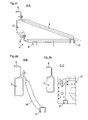
- Fig. 1a is shown schematically and by way of example a side view of an inventive support frame 1, which is laterally connected to a side member 2 of a not shown here in detail and two such, parallel longitudinal member 1 having commercial vehicle support structure.
- the support frame 1 consists of a frame frame 3, which, as in particular from the Fig. 1b to 1d can be seen, a first holding element 4, which, as shown in particular from Fig. 1d can be seen, is formed by a first frame part 5, which preferably has a pipe cross-section.
- This first frame part 5 is connected to an end portion facing the longitudinal member 2, which is formed bent or angled, connected to one, based on the vertical axis of the vehicle upper flange 6 of the longitudinal support 2 also formed here by a hollow profile, for example by means of one or more screw.
- a second frame part 7 of the retaining element 4 is connected to a lower end of the longitudinal member 2, namely indirectly with the interposition of an adapter element 8 connected to the longitudinal member 2 in a materially positive or non-positive manner.
- the connection takes place, for example by means of one or more screw connections.
- the second frame part 7 is angled or bent in the connection region on the adapter element 8, so that this rests on the adapter element 8, as well as the first frame member 5 on the upper flange 6 in a flat contact connection, resulting in a particularly stable connection of the two frame parts 5, 7 allows on the side rail 2.
- the second frame part 7 runs approximately horizontally and is, for example, materially bonded by means of only two spaced-apart support area frame parts 9, 10 extending essentially parallel to one another and to the side member 2, for example connected, which form a frame support area 11 for example, a fuel tank 12 described in more detail below.
- the upper, first frame part extends from the connection region on the upper flange portion 6, starting down to the in the image plane of the Fig. 1d right support area frame part 10 and is connected there for example cohesively.
- the holding element 13 is formed by a mounting wall 14, which in particular also from Fig. 1c it can be seen that a section along the line AA of Fig. 1b shows.
- This mounting wall 14 of, for example, a sheet metal material has a substantially rectangular and substantially over the entire support frame height or width extending outer contour, the recesses 15 and attachment points 16 in defined areas as mounting preparation for a defined installation or for a defined cultivation of attachments, which will be described in more detail below.
- the mounting wall 14 is, which in particular also from the Fig. 1a and the Fig. 1e . 1f . 1g , 1h, on the one hand fixed to the support area frame parts 9, 10, for example screwed there and / or materially connected.
- the mounting wall 14 also, for example non-positively by means of screws or alternatively and additionally cohesively, connected to a U-shaped mounting bracket 17, to which the mounting wall 14 preferably rests on this mounting bracket in a planar contact connection.
- This mounting bracket 17 then surrounds the longitudinal member 2 with a top U-bracket end region 18 in the direction of vertical axis of the vehicle and is connected to a folded abutment region in a planar abutment connection on the upper flange section 6, preferably screwed by means of a plurality of force-locking screw connections.
- the mounting bracket 17 is in turn indirectly connected via an adapter element 8, analogous to the second frame part 7 of the support member 4, at the bottom of the longitudinal member 2.
- the lower U-bracket end area 19 is preferably formed, for example, bent or angled formed that a flat abutment connection takes place on the adapter element 8.
- Fig. 1e to 1g are on the flat mounting wall 14 and the local installation preparations set several attachments, such as a boiler 20 and a controller 21 of a tire pressure control system. Further, a fuel additive pump 22 and a cab tilting pump 23 is fixed to the mounting wall 14. The determination is preferably carried out by means of a screw connection.
- a view corresponding to the arrow A of Fig. 1e shows, in the region of the recess 15 further comprises a fuel filter 24 is arranged.
- a fuel filter 24 is arranged in the region of the mounting wall 14 in the region of the mounting wall 14 also an edge bend 25 can be provided which has at least one, but preferably a plurality of mounting holes 26, through the lines, here by way of example a fuel line 27, can be passed. Due to the defined design and position of the mounting holes 26, such lines can thus be guided and supported particularly advantageously in the region of the frame frame 3.
- the flat mounting wall 14 can be further stiffened by at least one stiffening element 28.
- These stiffening elements which are formed for example by stiffening plates, preferably extend substantially downwardly from an upper end region of the mounting wall 14 (viewed in the vertical direction of the vehicle) and are supported, for example, in the region of the supporting region frame parts 9, 10 or at the peripheral bend 25 from.
- the stiffener may also be integrally formed on the mounting wall 14 or else, as shown by the two other stiffening elements 28, be formed by separate components.
- the frame-frame support area 11 is formed, in which, substantially "positively," the fuel tank 12 is received and mounted.
- a shell-like cover member which here exemplified by a cover plate 29 is, covered or encapsulated, whereby these components are shielded from the environment.
- the cover plate 29 is likewise fastened to the mounting wall 14 or in the region of the frame-frame support region 11.
- Fig. 1 In this embodiment of the Fig. 1 is thus on the support frame 1, unlike that described in the following Fig. 2 the case is, no fender tied. Rather, here is the fender 31 'spaced from the mounting wall side frame structure arranged (distance a), which in the Fig. 1b only shown extremely schematically. In the space between fender 31 'and support frame 1 or mounting wall 14 can then be arranged, for example, according to a particularly preferred embodiment, not shown here support, for example, a hydraulic support, the vehicle body. This support clearance is designated here by the reference numeral 31 ", the fender 31 'here being preferably connected to the side member 2.
- FIG. 2f another alternative embodiment is shown, in which the cover for covering the mounting wall attachment parts is formed in part by a fender wall portion 30 of a means of this fender wall portion 30 also connected to the frame frame 3 fender.
- the fender wall portion 30 at the free end of the fender here an exemplary bent or beveled trained Koterielanitatis Society 32 which rests on the frame frame support portion 11, in particular on a there beyond the mounting wall 14 also extended support area frame part 9, 10 and with this in a flat system connection is connected.
- the fender wall portion 30 then extends substantially parallel and spaced from the mounting wall 14 in the vehicle vertical axis direction upward, before it is then bent or bent.
- a roof plate 33 is provided, for example, of a sheet material, which is connected both to the fender wall portion 30 and to the mounting wall 14 is, for example by means of a frictional screw 34 shown here only extremely schematically.
- the screw 34 is shown here for the roof panel 33 only in the area of the fender wall portion 30, but may be formed on the side of the mounting wall as well.
- Fig. 2f can be further removed, in the area above the roof panel 33 here another mounting space 35 is formed in which then, for example, in turn, as previously a boiler 20 of a tire pressure control system can be mounted.
- Fig. 2f can also be found that in connection with the connection of a fender 31 on the frame frame 3 and the support frame 1, the mounting wall 14 does not necessarily have to be connected via a mounting bracket 17 on the longitudinal member 2 and thus not necessarily form a holding element corresponding to the holding element 13 , Rather, here, as shown only very schematically by the partially hidden by the fender wall portion 30 first frame part 5, also on this montagewand solution side of the support frame 1, a connection to the side member 2 by means of the holding element 4 corresponding identical structure.
- FIG. 2g an embodiment is shown in which on the right in the image plane, the connection of the wing 31 in the manner just described and at the same time on the side opposite the longitudinal beam extension direction and thus in the vehicle longitudinal direction side of the support frame 1, another fender 36 on the frame 3 is connected.
- the frame frame support region and thus the support frame 1 extends between two fenders 31, 36 and thus has a large support width.
- another functional part 37 for example a storage compartment or the like, can then be held on the frame frame 3.
- a further frame part 38 which in turn, like the previously described frame parts 9, 10 and 5, 7 may be formed by a hollow profile, at the upper flange portion 6 and here exemplified on the longitudinal beam 2 facing inner Abstweil Scheme frame part 9 connected.
Landscapes
- Engineering & Computer Science (AREA)
- Mechanical Engineering (AREA)
- Life Sciences & Earth Sciences (AREA)
- Sustainable Development (AREA)
- Sustainable Energy (AREA)
- Chemical & Material Sciences (AREA)
- Combustion & Propulsion (AREA)
- Transportation (AREA)
- Body Structure For Vehicles (AREA)
Applications Claiming Priority (1)
| Application Number | Priority Date | Filing Date | Title |
|---|---|---|---|
| DE102010025260.3A DE102010025260B4 (de) | 2010-06-26 | 2010-06-26 | Traggestell zur seitlichen Befestigung von Anbauteilen an einem Längsträger einer Nutzfahrzeug-Tragstruktur |
Publications (2)
| Publication Number | Publication Date |
|---|---|
| EP2399782A1 true EP2399782A1 (fr) | 2011-12-28 |
| EP2399782B1 EP2399782B1 (fr) | 2015-04-08 |
Family
ID=44653901
Family Applications (1)
| Application Number | Title | Priority Date | Filing Date |
|---|---|---|---|
| EP11001155.8A Active EP2399782B1 (fr) | 2010-06-26 | 2011-02-12 | Structure porteuse pour la fixation latérale de composants de construction sur un support longitudinal d'une structure porteuse de véhicule utilitaire |
Country Status (4)
| Country | Link |
|---|---|
| EP (1) | EP2399782B1 (fr) |
| CN (1) | CN102328692B (fr) |
| BR (1) | BRPI1102739B1 (fr) |
| DE (1) | DE102010025260B4 (fr) |
Cited By (2)
| Publication number | Priority date | Publication date | Assignee | Title |
|---|---|---|---|---|
| DE102015016389B3 (de) * | 2015-12-17 | 2017-02-09 | Audi Ag | Hilfsrahmen für ein Kraftfahrzeug |
| DE102015016391A1 (de) | 2015-12-17 | 2017-06-22 | Audi Ag | Hilfsrahmen für ein Kraftfahrzeug |
Families Citing this family (5)
| Publication number | Priority date | Publication date | Assignee | Title |
|---|---|---|---|---|
| DE102012011919A1 (de) | 2012-06-15 | 2013-12-19 | Audi Ag | Verstellbare Radaufhängung für die Räder einer Achse eines Kraftfahrzeugs |
| CN103863080A (zh) * | 2014-03-28 | 2014-06-18 | 安徽江淮汽车股份有限公司 | 一种电动商用车及其分体电池组的固定装置 |
| DE102014012713A1 (de) * | 2014-08-22 | 2016-02-25 | Man Truck & Bus Ag | Installations-Träger für ein Kraftfahrzeug |
| CN109131135B (zh) * | 2018-09-30 | 2021-04-06 | 江苏中路工程技术研究院有限公司 | 一种车载雷达固定装置 |
| DE102021127607A1 (de) | 2021-10-25 | 2023-04-27 | Man Truck & Bus Se | Träger für ein Außenverkleidungsteil |
Citations (12)
| Publication number | Priority date | Publication date | Assignee | Title |
|---|---|---|---|---|
| US2758845A (en) * | 1954-04-28 | 1956-08-14 | Prior Products Inc | Vehicle fuel tank assembly |
| DE1889305U (de) | 1963-11-05 | 1964-03-12 | Henschel Werke Ag | Halter fuer zubehoer an lkw-fahrgestellrahmen. |
| DE1555165A1 (de) | 1966-11-11 | 1970-09-24 | Daimler Benz Ag | Druckluftbremsanlage fuer Nutzkraftfahrzeuge |
| US5593167A (en) * | 1994-12-22 | 1997-01-14 | Volvo Gm Heavy Truck Corporation | Highway vehicle |
| DE19623845A1 (de) * | 1995-07-17 | 1997-01-23 | Scania Cv Ab | Ventilanordnung für Fahrzeuge |
| US6439329B1 (en) * | 1999-10-08 | 2002-08-27 | Ford Global Tech., Inc. | Integrated battery tray and reservoir assembly |
| DE19814975B4 (de) | 1998-04-03 | 2004-02-12 | Man Nutzfahrzeuge Ag | Trägersystem für Nutzfahrzeuge |
| DE102004055570A1 (de) | 2004-11-18 | 2006-05-24 | Daimlerchrysler Ag | Tragstruktur eines Nutzfahrzeugs |
| EP1686637A1 (fr) * | 2004-12-22 | 2006-08-02 | MAN Nutzfahrzeuge Aktiengesellschaft | Arrangement de plusieurs accumulateurs d'énergie dans un véhicule |
| DE102006044176A1 (de) * | 2006-09-15 | 2008-03-27 | Daimler Ag | Batterieträger für einen Lastkraftwagen |
| US20090000841A1 (en) * | 2007-06-26 | 2009-01-01 | Camas Reed | Battery boxes having aperture and vehicles including same |
| WO2009030367A1 (fr) * | 2007-08-30 | 2009-03-12 | Peguform Gmbh | Pièce moulée en matière plastique destinée à recevoir une batterie de véhicule |
Family Cites Families (7)
| Publication number | Priority date | Publication date | Assignee | Title |
|---|---|---|---|---|
| DE10328456A1 (de) | 2003-06-25 | 2005-01-20 | Daimlerchrysler Ag | Vorrichtung zur Befestigung eines Behälters zur Aufnahme von flüssigen Brennstoffen |
| DE102004005153B4 (de) | 2004-02-03 | 2006-06-22 | Daimlerchrysler Ag | Anbausystem für Nutzfahrzeuge |
| DE102004033909A1 (de) | 2004-07-14 | 2006-02-16 | Man Nutzfahrzeuge Ag | Nutzfahrzeug, insbesondere Lastkraftwagen |
| JP4408818B2 (ja) * | 2005-02-14 | 2010-02-03 | 本田技研工業株式会社 | マウント装置の取付構造 |
| SE530641C2 (sv) * | 2005-12-19 | 2008-07-29 | Volvo Lastvagnar Ab | Fastsättningsanordning för montering på en fordonsram |
| DE102008035450A1 (de) | 2008-07-30 | 2009-04-02 | Daimler Ag | Betriebsmitteltankanordnung |
| DE102009019193A1 (de) | 2009-04-28 | 2009-11-05 | Daimler Ag | Fahrzeug, insbesondere Nutzfahrzeug, mit wenigstens einem Behältnis zur Aufnahme von Kraftstoff |
-
2010
- 2010-06-26 DE DE102010025260.3A patent/DE102010025260B4/de active Active
-
2011
- 2011-02-12 EP EP11001155.8A patent/EP2399782B1/fr active Active
- 2011-06-24 CN CN201110179906.0A patent/CN102328692B/zh active Active
- 2011-06-24 BR BRPI1102739-8A patent/BRPI1102739B1/pt active IP Right Grant
Patent Citations (12)
| Publication number | Priority date | Publication date | Assignee | Title |
|---|---|---|---|---|
| US2758845A (en) * | 1954-04-28 | 1956-08-14 | Prior Products Inc | Vehicle fuel tank assembly |
| DE1889305U (de) | 1963-11-05 | 1964-03-12 | Henschel Werke Ag | Halter fuer zubehoer an lkw-fahrgestellrahmen. |
| DE1555165A1 (de) | 1966-11-11 | 1970-09-24 | Daimler Benz Ag | Druckluftbremsanlage fuer Nutzkraftfahrzeuge |
| US5593167A (en) * | 1994-12-22 | 1997-01-14 | Volvo Gm Heavy Truck Corporation | Highway vehicle |
| DE19623845A1 (de) * | 1995-07-17 | 1997-01-23 | Scania Cv Ab | Ventilanordnung für Fahrzeuge |
| DE19814975B4 (de) | 1998-04-03 | 2004-02-12 | Man Nutzfahrzeuge Ag | Trägersystem für Nutzfahrzeuge |
| US6439329B1 (en) * | 1999-10-08 | 2002-08-27 | Ford Global Tech., Inc. | Integrated battery tray and reservoir assembly |
| DE102004055570A1 (de) | 2004-11-18 | 2006-05-24 | Daimlerchrysler Ag | Tragstruktur eines Nutzfahrzeugs |
| EP1686637A1 (fr) * | 2004-12-22 | 2006-08-02 | MAN Nutzfahrzeuge Aktiengesellschaft | Arrangement de plusieurs accumulateurs d'énergie dans un véhicule |
| DE102006044176A1 (de) * | 2006-09-15 | 2008-03-27 | Daimler Ag | Batterieträger für einen Lastkraftwagen |
| US20090000841A1 (en) * | 2007-06-26 | 2009-01-01 | Camas Reed | Battery boxes having aperture and vehicles including same |
| WO2009030367A1 (fr) * | 2007-08-30 | 2009-03-12 | Peguform Gmbh | Pièce moulée en matière plastique destinée à recevoir une batterie de véhicule |
Cited By (3)
| Publication number | Priority date | Publication date | Assignee | Title |
|---|---|---|---|---|
| DE102015016389B3 (de) * | 2015-12-17 | 2017-02-09 | Audi Ag | Hilfsrahmen für ein Kraftfahrzeug |
| DE102015016391A1 (de) | 2015-12-17 | 2017-06-22 | Audi Ag | Hilfsrahmen für ein Kraftfahrzeug |
| DE102015016391B4 (de) | 2015-12-17 | 2019-04-18 | Audi Ag | Hilfsrahmen für ein Kraftfahrzeug |
Also Published As
| Publication number | Publication date |
|---|---|
| BRPI1102739A2 (pt) | 2012-12-04 |
| BRPI1102739B1 (pt) | 2020-07-28 |
| DE102010025260A1 (de) | 2011-12-29 |
| EP2399782B1 (fr) | 2015-04-08 |
| CN102328692B (zh) | 2014-04-09 |
| DE102010025260B4 (de) | 2022-01-27 |
| CN102328692A (zh) | 2012-01-25 |
Similar Documents
| Publication | Publication Date | Title |
|---|---|---|
| EP2165875B1 (fr) | Dispositif de fixation, notamment pour véhicule automobile | |
| EP2399782B1 (fr) | Structure porteuse pour la fixation latérale de composants de construction sur un support longitudinal d'une structure porteuse de véhicule utilitaire | |
| DE102009050495B4 (de) | Hilfsrahmen | |
| DE102005051947B4 (de) | Vorrichtung zur Aufnahme von Seitenkräften bei einem Seitenaufprall eines Kraftfahrzeugs | |
| EP2719565B1 (fr) | Structure avant pour un véhicule automobile | |
| EP1073579A1 (fr) | Coque d'un vehicule automobile | |
| DE102008032543A1 (de) | Crashbox für ein Kraftfahrzeug | |
| EP3158842B1 (fr) | Véhicule agricole | |
| EP2030874B1 (fr) | Poids lourd doté d'une cabine de conducteur spéciale | |
| DE102016103082A1 (de) | Hinterer Abschnitt der Fahrzeugkarosseriestruktur eines Kraftfahrzeugs | |
| EP1634798B1 (fr) | Procédé d'interconnection et adaptateur pour châssis reporté pour tête de traction d'un véhicle | |
| EP3758960B1 (fr) | Système porteur d'une galerie ou d'un équipement de couplage | |
| DE102006009189B3 (de) | Befestigungsanordnung von Außenanbauteilen an einem Tragrahmen eines Lastkraftwagens | |
| DE102010022158B4 (de) | Vorderwagenstruktur einer Fahrzeugkarosserie | |
| EP1619106B1 (fr) | Support universel pour le montage d'un composant de véhicule sur le châssis d'un véhicule poids lourd | |
| DE102007018474A1 (de) | Fahrzeug | |
| EP1839959B1 (fr) | Elément récepteur destiné à la fixation d'un amortisseur de choc | |
| DE102008050129A1 (de) | Fahrzeugaufbau eines Cabriolet-Fahrzeugs | |
| DE10214495B4 (de) | Lastkraftwagen mit einer Anzahl von in einer kompakten Baugruppe hinter dem Fahrerhaus zusammengefassten Fahrzeugteilen | |
| EP0591727B1 (fr) | Véhicule utilitaire, en particulier camion avec cabine à l'avant | |
| DE102005033030A1 (de) | Karosserievorbau eines Kraftwagens | |
| DE102012013910A1 (de) | Rahmentragstruktur mit nach oben gekröpften Tragabschnitten | |
| DE102018222171B3 (de) | Anordnung einer Schutzstruktur für einen Montageträger in einem Vorderwagen eines Kraftfahrzeuges | |
| DE102011122471A1 (de) | Anhängevorrichtung für ein Fahrzeug | |
| EP2684724B1 (fr) | Structure de support en forme de cadre avec installation de refroidissement |
Legal Events
| Date | Code | Title | Description |
|---|---|---|---|
| AK | Designated contracting states |
Kind code of ref document: A1 Designated state(s): AL AT BE BG CH CY CZ DE DK EE ES FI FR GB GR HR HU IE IS IT LI LT LU LV MC MK MT NL NO PL PT RO RS SE SI SK SM TR |
|
| AX | Request for extension of the european patent |
Extension state: BA ME |
|
| PUAI | Public reference made under article 153(3) epc to a published international application that has entered the european phase |
Free format text: ORIGINAL CODE: 0009012 |
|
| 17P | Request for examination filed |
Effective date: 20111215 |
|
| RIN1 | Information on inventor provided before grant (corrected) |
Inventor name: TRINK, MARIO Inventor name: SCHERR, EMANUEL |
|
| 17Q | First examination report despatched |
Effective date: 20140403 |
|
| GRAP | Despatch of communication of intention to grant a patent |
Free format text: ORIGINAL CODE: EPIDOSNIGR1 |
|
| INTG | Intention to grant announced |
Effective date: 20141119 |
|
| GRAS | Grant fee paid |
Free format text: ORIGINAL CODE: EPIDOSNIGR3 |
|
| GRAA | (expected) grant |
Free format text: ORIGINAL CODE: 0009210 |
|
| AK | Designated contracting states |
Kind code of ref document: B1 Designated state(s): AL AT BE BG CH CY CZ DE DK EE ES FI FR GB GR HR HU IE IS IT LI LT LU LV MC MK MT NL NO PL PT RO RS SE SI SK SM TR |
|
| REG | Reference to a national code |
Ref country code: GB Ref legal event code: FG4D Free format text: NOT ENGLISH |
|
| REG | Reference to a national code |
Ref country code: CH Ref legal event code: EP |
|
| REG | Reference to a national code |
Ref country code: IE Ref legal event code: FG4D Free format text: LANGUAGE OF EP DOCUMENT: GERMAN |
|
| REG | Reference to a national code |
Ref country code: AT Ref legal event code: REF Ref document number: 720287 Country of ref document: AT Kind code of ref document: T Effective date: 20150515 |
|
| REG | Reference to a national code |
Ref country code: DE Ref legal event code: R096 Ref document number: 502011006482 Country of ref document: DE Effective date: 20150521 |
|
| REG | Reference to a national code |
Ref country code: NL Ref legal event code: T3 |
|
| REG | Reference to a national code |
Ref country code: SE Ref legal event code: TRGR |
|
| REG | Reference to a national code |
Ref country code: LT Ref legal event code: MG4D |
|
| PG25 | Lapsed in a contracting state [announced via postgrant information from national office to epo] |
Ref country code: HR Free format text: LAPSE BECAUSE OF FAILURE TO SUBMIT A TRANSLATION OF THE DESCRIPTION OR TO PAY THE FEE WITHIN THE PRESCRIBED TIME-LIMIT Effective date: 20150408 Ref country code: PT Free format text: LAPSE BECAUSE OF FAILURE TO SUBMIT A TRANSLATION OF THE DESCRIPTION OR TO PAY THE FEE WITHIN THE PRESCRIBED TIME-LIMIT Effective date: 20150810 Ref country code: LT Free format text: LAPSE BECAUSE OF FAILURE TO SUBMIT A TRANSLATION OF THE DESCRIPTION OR TO PAY THE FEE WITHIN THE PRESCRIBED TIME-LIMIT Effective date: 20150408 Ref country code: NO Free format text: LAPSE BECAUSE OF FAILURE TO SUBMIT A TRANSLATION OF THE DESCRIPTION OR TO PAY THE FEE WITHIN THE PRESCRIBED TIME-LIMIT Effective date: 20150708 Ref country code: ES Free format text: LAPSE BECAUSE OF FAILURE TO SUBMIT A TRANSLATION OF THE DESCRIPTION OR TO PAY THE FEE WITHIN THE PRESCRIBED TIME-LIMIT Effective date: 20150408 Ref country code: FI Free format text: LAPSE BECAUSE OF FAILURE TO SUBMIT A TRANSLATION OF THE DESCRIPTION OR TO PAY THE FEE WITHIN THE PRESCRIBED TIME-LIMIT Effective date: 20150408 |
|
| PG25 | Lapsed in a contracting state [announced via postgrant information from national office to epo] |
Ref country code: RS Free format text: LAPSE BECAUSE OF FAILURE TO SUBMIT A TRANSLATION OF THE DESCRIPTION OR TO PAY THE FEE WITHIN THE PRESCRIBED TIME-LIMIT Effective date: 20150408 Ref country code: IS Free format text: LAPSE BECAUSE OF FAILURE TO SUBMIT A TRANSLATION OF THE DESCRIPTION OR TO PAY THE FEE WITHIN THE PRESCRIBED TIME-LIMIT Effective date: 20150808 Ref country code: LV Free format text: LAPSE BECAUSE OF FAILURE TO SUBMIT A TRANSLATION OF THE DESCRIPTION OR TO PAY THE FEE WITHIN THE PRESCRIBED TIME-LIMIT Effective date: 20150408 Ref country code: GR Free format text: LAPSE BECAUSE OF FAILURE TO SUBMIT A TRANSLATION OF THE DESCRIPTION OR TO PAY THE FEE WITHIN THE PRESCRIBED TIME-LIMIT Effective date: 20150709 |
|
| REG | Reference to a national code |
Ref country code: DE Ref legal event code: R097 Ref document number: 502011006482 Country of ref document: DE |
|
| PG25 | Lapsed in a contracting state [announced via postgrant information from national office to epo] |
Ref country code: DK Free format text: LAPSE BECAUSE OF FAILURE TO SUBMIT A TRANSLATION OF THE DESCRIPTION OR TO PAY THE FEE WITHIN THE PRESCRIBED TIME-LIMIT Effective date: 20150408 Ref country code: EE Free format text: LAPSE BECAUSE OF FAILURE TO SUBMIT A TRANSLATION OF THE DESCRIPTION OR TO PAY THE FEE WITHIN THE PRESCRIBED TIME-LIMIT Effective date: 20150408 |
|
| PLBE | No opposition filed within time limit |
Free format text: ORIGINAL CODE: 0009261 |
|
| STAA | Information on the status of an ep patent application or granted ep patent |
Free format text: STATUS: NO OPPOSITION FILED WITHIN TIME LIMIT |
|
| PG25 | Lapsed in a contracting state [announced via postgrant information from national office to epo] |
Ref country code: SK Free format text: LAPSE BECAUSE OF FAILURE TO SUBMIT A TRANSLATION OF THE DESCRIPTION OR TO PAY THE FEE WITHIN THE PRESCRIBED TIME-LIMIT Effective date: 20150408 Ref country code: CZ Free format text: LAPSE BECAUSE OF FAILURE TO SUBMIT A TRANSLATION OF THE DESCRIPTION OR TO PAY THE FEE WITHIN THE PRESCRIBED TIME-LIMIT Effective date: 20150408 Ref country code: RO Free format text: LAPSE BECAUSE OF NON-PAYMENT OF DUE FEES Effective date: 20150408 Ref country code: PL Free format text: LAPSE BECAUSE OF FAILURE TO SUBMIT A TRANSLATION OF THE DESCRIPTION OR TO PAY THE FEE WITHIN THE PRESCRIBED TIME-LIMIT Effective date: 20150408 |
|
| REG | Reference to a national code |
Ref country code: FR Ref legal event code: PLFP Year of fee payment: 6 |
|
| 26N | No opposition filed |
Effective date: 20160111 |
|
| PG25 | Lapsed in a contracting state [announced via postgrant information from national office to epo] |
Ref country code: SI Free format text: LAPSE BECAUSE OF FAILURE TO SUBMIT A TRANSLATION OF THE DESCRIPTION OR TO PAY THE FEE WITHIN THE PRESCRIBED TIME-LIMIT Effective date: 20150408 Ref country code: BE Free format text: LAPSE BECAUSE OF NON-PAYMENT OF DUE FEES Effective date: 20160229 |
|
| PG25 | Lapsed in a contracting state [announced via postgrant information from national office to epo] |
Ref country code: LU Free format text: LAPSE BECAUSE OF FAILURE TO SUBMIT A TRANSLATION OF THE DESCRIPTION OR TO PAY THE FEE WITHIN THE PRESCRIBED TIME-LIMIT Effective date: 20160212 Ref country code: MC Free format text: LAPSE BECAUSE OF FAILURE TO SUBMIT A TRANSLATION OF THE DESCRIPTION OR TO PAY THE FEE WITHIN THE PRESCRIBED TIME-LIMIT Effective date: 20150408 |
|
| REG | Reference to a national code |
Ref country code: CH Ref legal event code: PL |
|
| GBPC | Gb: european patent ceased through non-payment of renewal fee |
Effective date: 20160212 |
|
| PG25 | Lapsed in a contracting state [announced via postgrant information from national office to epo] |
Ref country code: CH Free format text: LAPSE BECAUSE OF NON-PAYMENT OF DUE FEES Effective date: 20160229 Ref country code: LI Free format text: LAPSE BECAUSE OF NON-PAYMENT OF DUE FEES Effective date: 20160229 |
|
| REG | Reference to a national code |
Ref country code: IE Ref legal event code: MM4A |
|
| PG25 | Lapsed in a contracting state [announced via postgrant information from national office to epo] |
Ref country code: GB Free format text: LAPSE BECAUSE OF NON-PAYMENT OF DUE FEES Effective date: 20160212 Ref country code: IE Free format text: LAPSE BECAUSE OF NON-PAYMENT OF DUE FEES Effective date: 20160212 |
|
| REG | Reference to a national code |
Ref country code: FR Ref legal event code: PLFP Year of fee payment: 7 |
|
| REG | Reference to a national code |
Ref country code: AT Ref legal event code: MM01 Ref document number: 720287 Country of ref document: AT Kind code of ref document: T Effective date: 20160212 |
|
| PG25 | Lapsed in a contracting state [announced via postgrant information from national office to epo] |
Ref country code: AT Free format text: LAPSE BECAUSE OF NON-PAYMENT OF DUE FEES Effective date: 20160212 |
|
| PG25 | Lapsed in a contracting state [announced via postgrant information from national office to epo] |
Ref country code: MT Free format text: LAPSE BECAUSE OF FAILURE TO SUBMIT A TRANSLATION OF THE DESCRIPTION OR TO PAY THE FEE WITHIN THE PRESCRIBED TIME-LIMIT Effective date: 20150408 |
|
| REG | Reference to a national code |
Ref country code: FR Ref legal event code: PLFP Year of fee payment: 8 |
|
| PG25 | Lapsed in a contracting state [announced via postgrant information from national office to epo] |
Ref country code: HU Free format text: LAPSE BECAUSE OF FAILURE TO SUBMIT A TRANSLATION OF THE DESCRIPTION OR TO PAY THE FEE WITHIN THE PRESCRIBED TIME-LIMIT; INVALID AB INITIO Effective date: 20110212 Ref country code: SM Free format text: LAPSE BECAUSE OF FAILURE TO SUBMIT A TRANSLATION OF THE DESCRIPTION OR TO PAY THE FEE WITHIN THE PRESCRIBED TIME-LIMIT Effective date: 20150408 Ref country code: CY Free format text: LAPSE BECAUSE OF FAILURE TO SUBMIT A TRANSLATION OF THE DESCRIPTION OR TO PAY THE FEE WITHIN THE PRESCRIBED TIME-LIMIT Effective date: 20150408 |
|
| PG25 | Lapsed in a contracting state [announced via postgrant information from national office to epo] |
Ref country code: MK Free format text: LAPSE BECAUSE OF FAILURE TO SUBMIT A TRANSLATION OF THE DESCRIPTION OR TO PAY THE FEE WITHIN THE PRESCRIBED TIME-LIMIT Effective date: 20150408 Ref country code: TR Free format text: LAPSE BECAUSE OF FAILURE TO SUBMIT A TRANSLATION OF THE DESCRIPTION OR TO PAY THE FEE WITHIN THE PRESCRIBED TIME-LIMIT Effective date: 20150408 |
|
| PG25 | Lapsed in a contracting state [announced via postgrant information from national office to epo] |
Ref country code: BG Free format text: LAPSE BECAUSE OF FAILURE TO SUBMIT A TRANSLATION OF THE DESCRIPTION OR TO PAY THE FEE WITHIN THE PRESCRIBED TIME-LIMIT Effective date: 20150408 |
|
| PG25 | Lapsed in a contracting state [announced via postgrant information from national office to epo] |
Ref country code: AL Free format text: LAPSE BECAUSE OF FAILURE TO SUBMIT A TRANSLATION OF THE DESCRIPTION OR TO PAY THE FEE WITHIN THE PRESCRIBED TIME-LIMIT Effective date: 20150408 |
|
| REG | Reference to a national code |
Ref country code: DE Ref legal event code: R081 Ref document number: 502011006482 Country of ref document: DE Owner name: MAN TRUCK & BUS SE, DE Free format text: FORMER OWNER: MAN TRUCK & BUS AG, 80995 MUENCHEN, DE |
|
| PGFP | Annual fee paid to national office [announced via postgrant information from national office to epo] |
Ref country code: NL Payment date: 20260220 Year of fee payment: 16 |
|
| PGFP | Annual fee paid to national office [announced via postgrant information from national office to epo] |
Ref country code: SE Payment date: 20260223 Year of fee payment: 16 |
|
| PGFP | Annual fee paid to national office [announced via postgrant information from national office to epo] |
Ref country code: DE Payment date: 20260220 Year of fee payment: 16 |
|
| PGFP | Annual fee paid to national office [announced via postgrant information from national office to epo] |
Ref country code: IT Payment date: 20260220 Year of fee payment: 16 |
|
| PGFP | Annual fee paid to national office [announced via postgrant information from national office to epo] |
Ref country code: FR Payment date: 20260224 Year of fee payment: 16 |