EP2400148A2 - Pales d'éoliennes avec éléments de vortex aérodynamique - Google Patents
Pales d'éoliennes avec éléments de vortex aérodynamique Download PDFInfo
- Publication number
- EP2400148A2 EP2400148A2 EP20110170657 EP11170657A EP2400148A2 EP 2400148 A2 EP2400148 A2 EP 2400148A2 EP 20110170657 EP20110170657 EP 20110170657 EP 11170657 A EP11170657 A EP 11170657A EP 2400148 A2 EP2400148 A2 EP 2400148A2
- Authority
- EP
- European Patent Office
- Prior art keywords
- wind turbine
- face
- wind
- blade
- vortex
- Prior art date
- Legal status (The legal status is an assumption and is not a legal conclusion. Google has not performed a legal analysis and makes no representation as to the accuracy of the status listed.)
- Granted
Links
Images


Classifications
-
- F—MECHANICAL ENGINEERING; LIGHTING; HEATING; WEAPONS; BLASTING
- F03—MACHINES OR ENGINES FOR LIQUIDS; WIND, SPRING, OR WEIGHT MOTORS; PRODUCING MECHANICAL POWER OR A REACTIVE PROPULSIVE THRUST, NOT OTHERWISE PROVIDED FOR
- F03D—WIND MOTORS
- F03D1/00—Wind motors with rotation axis substantially parallel to the air flow entering the rotor
- F03D1/06—Rotors
- F03D1/0608—Rotors characterised by their aerodynamic shape
- F03D1/0633—Rotors characterised by their aerodynamic shape of the blades
-
- F—MECHANICAL ENGINEERING; LIGHTING; HEATING; WEAPONS; BLASTING
- F03—MACHINES OR ENGINES FOR LIQUIDS; WIND, SPRING, OR WEIGHT MOTORS; PRODUCING MECHANICAL POWER OR A REACTIVE PROPULSIVE THRUST, NOT OTHERWISE PROVIDED FOR
- F03D—WIND MOTORS
- F03D1/00—Wind motors with rotation axis substantially parallel to the air flow entering the rotor
- F03D1/06—Rotors
- F03D1/065—Rotors characterised by their construction elements
- F03D1/0675—Rotors characterised by their construction elements of the blades
-
- F—MECHANICAL ENGINEERING; LIGHTING; HEATING; WEAPONS; BLASTING
- F05—INDEXING SCHEMES RELATING TO ENGINES OR PUMPS IN VARIOUS SUBCLASSES OF CLASSES F01-F04
- F05B—INDEXING SCHEME RELATING TO WIND, SPRING, WEIGHT, INERTIA OR LIKE MOTORS, TO MACHINES OR ENGINES FOR LIQUIDS COVERED BY SUBCLASSES F03B, F03D AND F03G
- F05B2240/00—Components
- F05B2240/10—Stators
- F05B2240/12—Fluid guiding means, e.g. vanes
- F05B2240/122—Vortex generators, turbulators, or the like, for mixing
-
- F—MECHANICAL ENGINEERING; LIGHTING; HEATING; WEAPONS; BLASTING
- F05—INDEXING SCHEMES RELATING TO ENGINES OR PUMPS IN VARIOUS SUBCLASSES OF CLASSES F01-F04
- F05B—INDEXING SCHEME RELATING TO WIND, SPRING, WEIGHT, INERTIA OR LIKE MOTORS, TO MACHINES OR ENGINES FOR LIQUIDS COVERED BY SUBCLASSES F03B, F03D AND F03G
- F05B2240/00—Components
- F05B2240/20—Rotors
- F05B2240/30—Characteristics of rotor blades, i.e. of any element transforming dynamic fluid energy to or from rotational energy and being attached to a rotor
- F05B2240/306—Surface measures
- F05B2240/3062—Vortex generators
-
- F—MECHANICAL ENGINEERING; LIGHTING; HEATING; WEAPONS; BLASTING
- F05—INDEXING SCHEMES RELATING TO ENGINES OR PUMPS IN VARIOUS SUBCLASSES OF CLASSES F01-F04
- F05B—INDEXING SCHEME RELATING TO WIND, SPRING, WEIGHT, INERTIA OR LIKE MOTORS, TO MACHINES OR ENGINES FOR LIQUIDS COVERED BY SUBCLASSES F03B, F03D AND F03G
- F05B2240/00—Components
- F05B2240/20—Rotors
- F05B2240/30—Characteristics of rotor blades, i.e. of any element transforming dynamic fluid energy to or from rotational energy and being attached to a rotor
- F05B2240/32—Characteristics of rotor blades, i.e. of any element transforming dynamic fluid energy to or from rotational energy and being attached to a rotor with roughened surface
-
- F—MECHANICAL ENGINEERING; LIGHTING; HEATING; WEAPONS; BLASTING
- F05—INDEXING SCHEMES RELATING TO ENGINES OR PUMPS IN VARIOUS SUBCLASSES OF CLASSES F01-F04
- F05B—INDEXING SCHEME RELATING TO WIND, SPRING, WEIGHT, INERTIA OR LIKE MOTORS, TO MACHINES OR ENGINES FOR LIQUIDS COVERED BY SUBCLASSES F03B, F03D AND F03G
- F05B2250/00—Geometry
- F05B2250/10—Geometry two-dimensional
- F05B2250/19—Geometry two-dimensional machined; miscellaneous
- F05B2250/192—Geometry two-dimensional machined; miscellaneous beveled
-
- F—MECHANICAL ENGINEERING; LIGHTING; HEATING; WEAPONS; BLASTING
- F05—INDEXING SCHEMES RELATING TO ENGINES OR PUMPS IN VARIOUS SUBCLASSES OF CLASSES F01-F04
- F05B—INDEXING SCHEME RELATING TO WIND, SPRING, WEIGHT, INERTIA OR LIKE MOTORS, TO MACHINES OR ENGINES FOR LIQUIDS COVERED BY SUBCLASSES F03B, F03D AND F03G
- F05B2250/00—Geometry
- F05B2250/70—Shape
-
- Y—GENERAL TAGGING OF NEW TECHNOLOGICAL DEVELOPMENTS; GENERAL TAGGING OF CROSS-SECTIONAL TECHNOLOGIES SPANNING OVER SEVERAL SECTIONS OF THE IPC; TECHNICAL SUBJECTS COVERED BY FORMER USPC CROSS-REFERENCE ART COLLECTIONS [XRACs] AND DIGESTS
- Y02—TECHNOLOGIES OR APPLICATIONS FOR MITIGATION OR ADAPTATION AGAINST CLIMATE CHANGE
- Y02E—REDUCTION OF GREENHOUSE GAS [GHG] EMISSIONS, RELATED TO ENERGY GENERATION, TRANSMISSION OR DISTRIBUTION
- Y02E10/00—Energy generation through renewable energy sources
- Y02E10/70—Wind energy
- Y02E10/72—Wind turbines with rotation axis in wind direction
Definitions
- the present invention relates generally to the field of wind turbines, and more particularly to turbine blades having an aerodynamic vortex element on the flow surfaces thereof.
- Turbine blades are the primary elements of wind turbines for converting wind energy into electrical energy.
- the working principle of the blades resembles that of an airplane wing.
- the blades have the cross-sectional profile of an airfoil such that, during operation, air flows over the blade producing a pressure difference between the sides. Consequently, a lift force, which is directed from a pressure side towards a suction side, acts on the blade.
- the lift force generates torque on the main rotor shaft, which is geared to a generator for producing electricity.
- the lift force is generated when the flow from the leading edge to the trailing edge creates a pressure difference between the top and bottom surfaces of the blade.
- the flow is attached to the top surface from the leading edge to the trailing edge.
- the angle of attack of the flow exceeds a certain critical angle, the flow does not reach the trailing edge, but leaves the surface at a flow separation line. Beyond this line, the flow direction is generally reversed, i.e. it flows from the trailing edge backward to the separation line.
- a blade section extracts much less energy from the flow when it separates.
- Flow separation depends on a number of factors, such as incoming air flow characteristics (e.g. Reynolds number, wind speed, in-flow atmospheric turbulence) and characteristics of the blade (e.g. airfoil sections, blade chord and thickness, twist distribution, pitch angle, etc).
- the detached-flow region also leads to an increase in drag force, mainly due to a pressure difference between the upstream attached-flow region and the downstream detached-flow region.
- Flow separation tends to be more prevalent nearer the blade root due to the relatively great angle of attack of the blade flow surfaces in this region as compared to the blade tip.
- Vortex generators serve to create local regions of turbulent airflow over the surface of the blade as a means to prolong flow separation and thus optimize aerodynamic airflow around the blade contour.
- Conventional vortex generators are typically sheet metal and defined as “fins” or shaped structures on the suction side of the turbine blade.
- Conventional vortex generators are not, however, without drawbacks. Vortex generators create drag and tend to be noisy.
- a wind turbine blade having a suction side surface and a pressure side surface.
- a plurality of vortex elements are formed on either one or both of the surfaces.
- the vortex elements have an upwardly inclined wind face and a downwardly inclined slip face, with the wind face and slip face meeting at a generally open-ended U-shaped ridge that defines side horns.
- the side horns decrease in height from a forward most portion of the ridge to the suction side surface or pressure side surface.
- the wind face and the slip face are formed by flat walls disposed at constant angles.
- the wind face may have a flat front wall and opposite flat side walls
- the slip face may similarly have a flat front wall and opposite flat side walls.
- the vortex elements have a semi-hemispherical crescent shape with a convex wind face and a concave slip face, with the U-shaped ridge comprising a continuously curved arc shape.
- the vortex elements may be placed at any location on either or both of the blade's flow surfaces wherein it is desired to modify the aerodynamic characteristics of the surface.
- the vortex elements are defined on the suction side surface at a chord length of between about 15% to about 65%.
- the vortex elements may be disposed closer to a root portion of the blade as compared to a tip portion, or closer to the tip portion as compared to the root portion.
- the blade may incorporate the unique vortex elements with conventional vortex generators, such as wedge or fin-type vortex generators.
- the vortex elements may be provided at a defined region of the blade while the vortex generators may be provided at a different region of the blade, or the vortex generators and vortex elements may be intermingled.
- Embodiments of the invention also encompass a wind turbine having one or more turbine blades configured with the unique vortex elements as described herein.
- Fig. 1 illustrates a wind turbine 10 of conventional construction.
- the wind turbine 10 includes a tower 12 with a nacelle 14 mounted thereon.
- a plurality of turbine blades 16 are mounted to a rotor hub 18, which is in turn connected to a main flange that turns a main rotor shaft.
- the wind turbine power generation and control components are housed within the nacelle 14.
- the view of Fig. 1 is provided for illustrative purposes only to place the present invention in an exemplary field of use. It should be appreciated that the embodiments of the invention are not limited to any particular type of wind turbine configuration.
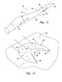
- Figs. 2 depicts a wind turbine blade 16 incorporating aspects of the invention.
- the blades 16 include a suction side surface 20, a pressure side surface 22, a leading edge 24, and a trailing edge 26.
- the blades extend from a root portion 28 to a tip portion 30.
- a plurality of unique vortex elements 32 in accordance with aspects of the invention described in greater detail below are formed on either or both of the surfaces 22 and 24.
- the vortex elements 32 are depicted on the suction side surface 20 for illustrative purposes only. It should be appreciated that the vortex elements 32 could also be provided on the pressure side surface 22.
- the vortex elements 32 may be placed at any location on either or both of the blade's flow surfaces 20, 22 wherein it is desired to modify the aerodynamic characteristics of the surface.
- the vortex elements 32 are defined on the suction side surface 20 at a chord length of between about 15% to about 65%, as depicted in Fig. 2 .
- the vortex elements 32 may be disposed closer to a root portion 28 of the blade as compared to a tip portion 30, or closer to the tip portion 30 as compared to the root portion 28. It should be understood that the invention is not limited to any particular placement of the vortex elements 32 on either or both flow surfaces 20, 22 of the blade 16.
- the vortex elements 32 may have different shape configurations within the scope and spirit of the invention.
- the vortex elements 32 have an upwardly inclined wind face 40 and a downwardly inclined slip face 44, with the wind face 40 and slip face 44 meeting at a generally open-ended U-shaped ridge 42 that defines side horns 46.
- the side horns 46 decrease in height from a forward most portion 56 ( Fig. 6 ) of the ridge 42 and slope down to the surface 20on which the vortex elements 32 are formed.
- the wind face 40 and slip face 44 may have various shapes and configurations.
- the wind face 40 and the slip face 44 are formed by generally flat inclined wall segments arranged to form a generally multisided base 38.
- the wind face 40 in this embodiment may include a flat front wall 48 and flat side walls 50. These walls are inclined at a relatively constant angle from the surface 20 to the ridge line 42.
- the slip face 44 may include a flat front wall 52 and flat side walls 54 that are also inclined at a relatively constant angle up to the ridge line 42.
- the vortex elements 32 have a generally semi-hemispherical crescent shape.
- the vortex element 32 includes a generally semi-circular base 38 in the forward portion thereof that faces the direction of wind flow over the surface 20 (as indicated by the arrows in Fig. 3 ).
- the wind face 44 includes a generally convex surface wall 58 around the perimeter of the base 38 that extends from the surface 20 to the ridge line 42.
- the slip face 44 includes a generally concave wall 60 that extends from the surface 20 to the ridge line 42.
- the wind face 40 and slip face 44 merge at the crescent-shaped ridge line 42 that slopes down from the forward most portion of the ridge line 42 to the base 38 along the side horns 46.
- the base 38 along the slip face 44 also has a generally crescent shape such that the side horns 46 are defmed as depicted in Fig. 3 .
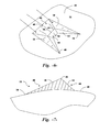
- Fig. 4 is a cut-away profile view of the vortex element 32 and particularly illustrates the convex wind face 40 and the concave slip face 44, as well as the ridge line 42.
- the vortex elements 32 may be considered in certain embodiments as being modeled after naturally occurring crescent sand dunes, which act as vortex generators in nature.
- Fig. 5 is a computer generated depiction of wind flow over a crescent vortex element 32. It is readily seen in Fig. 5 that air flow over the forward wind face 40 drops over the ridge and develops into trailing vortexes that are channeled along the horns 46 at the slip face 44.
- the unique crescent sand dune shape generates the aerodynamic vortexes with out significantly increasing drag, which is highly desirable for a vortex generator on a wind turbine flow surface.
- the blade 16 may incorporate the unique vortex elements 32 with conventional vortex generators 34, such as fin or wedge-type vortex generators.
- conventional vortex generators 34 such as fin or wedge-type vortex generators.
- the vortex elements 32 may be provided at a defined region of the blade 16 while the vortex generators 34 may be provided at a different region of the blade 16.
- the vortex elements 32 may be configured at the root portion 28 to provide increased lift with little additional drag (particularly desirable in low wind speed conditions), while conventional wedge or fin-type vortex generators 34 are provided at the higher speed regions of the blade closer to the blade tip 30.
- the vortex elements 32 may be located closer towards the tip portion 30 than the root portion 28.
- the present invention encompasses any configuration of wind turbine 10 ( Fig. 1 ) that includes one or more blades 16 incorporating at least one of the unique vortex elements 32 as described herein.
Landscapes
- Engineering & Computer Science (AREA)
- Life Sciences & Earth Sciences (AREA)
- Sustainable Development (AREA)
- Sustainable Energy (AREA)
- Chemical & Material Sciences (AREA)
- Combustion & Propulsion (AREA)
- Mechanical Engineering (AREA)
- General Engineering & Computer Science (AREA)
- Physics & Mathematics (AREA)
- Fluid Mechanics (AREA)
- Wind Motors (AREA)
Applications Claiming Priority (1)
| Application Number | Priority Date | Filing Date | Title |
|---|---|---|---|
| US12/821,725 US8047801B2 (en) | 2010-06-23 | 2010-06-23 | Wind turbine blades with aerodynamic vortex elements |
Publications (3)
| Publication Number | Publication Date |
|---|---|
| EP2400148A2 true EP2400148A2 (fr) | 2011-12-28 |
| EP2400148A3 EP2400148A3 (fr) | 2012-04-18 |
| EP2400148B1 EP2400148B1 (fr) | 2015-08-12 |
Family
ID=44143150
Family Applications (1)
| Application Number | Title | Priority Date | Filing Date |
|---|---|---|---|
| EP11170657.8A Active EP2400148B1 (fr) | 2010-06-23 | 2011-06-21 | Pales d'éoliennes avec éléments de vortex aérodynamique |
Country Status (5)
| Country | Link |
|---|---|
| US (1) | US8047801B2 (fr) |
| EP (1) | EP2400148B1 (fr) |
| CN (1) | CN102297097B (fr) |
| DK (1) | DK2400148T3 (fr) |
| ES (1) | ES2546485T3 (fr) |
Cited By (1)
| Publication number | Priority date | Publication date | Assignee | Title |
|---|---|---|---|---|
| EP4610485A1 (fr) | 2024-02-28 | 2025-09-03 | Nordex Energy SE & Co. KG | Un générateur de tourbillons pour une pale de rotor d'éolienne |
Families Citing this family (52)
| Publication number | Priority date | Publication date | Assignee | Title |
|---|---|---|---|---|
| GB0803730D0 (en) * | 2008-02-29 | 2008-04-09 | Airbus Uk Ltd | Shock bump array |
| CN102792022B (zh) * | 2009-09-18 | 2016-02-24 | 麻省理工学院 | 会聚的太阳能电力系统 |
| EP2484898B1 (fr) * | 2011-02-04 | 2014-04-23 | LM WP Patent Holding A/S | Dispositif générateur de vortex doté de sections biseautées pour une éolienne |
| ES2451568T3 (es) * | 2011-02-04 | 2014-03-27 | Lm Wind Power A/S | Generador de torbellinos para turbina eólica con una base que tiene un rebaje para adhesivo |
| EP2548800A1 (fr) | 2011-07-22 | 2013-01-23 | LM Wind Power A/S | Procédés pour rééquiper des générateurs de vortex sur une pale d'éolienne |
| WO2013014015A2 (fr) * | 2011-07-22 | 2013-01-31 | Lm Wind Power A/S | Disposition de générateurs de tourbillons pour profil d'aile |
| US20130047978A1 (en) * | 2011-08-31 | 2013-02-28 | Massachusetts Institute Of Technology | Vortex-induced cleaning of surfaces |
| NZ703435A (en) * | 2012-05-28 | 2016-06-24 | Sideways Sports Ltd | Watercraft fin |
| NL2009286C2 (en) * | 2012-08-06 | 2014-02-10 | Stichting Energie | Swallow tail airfoil. |
| US20140328688A1 (en) | 2013-05-03 | 2014-11-06 | General Electric Company | Rotor blade assembly having vortex generators for wind turbine |
| US9494132B2 (en) * | 2013-05-07 | 2016-11-15 | General Electric Company | Airflow modifying assembly for a rotor blade of a wind turbine |
| US9267427B2 (en) | 2013-06-11 | 2016-02-23 | Ford Global Technologies, Llc | Variable geometry turbine vane |
| US20150010407A1 (en) * | 2013-07-08 | 2015-01-08 | Alonso O. Zamora Rodriguez | Reduced noise vortex generator for wind turbine blade |
| US10443562B2 (en) * | 2013-09-02 | 2019-10-15 | Wobben Properties Gmbh | Vortex generator for a wind turbine |
| US9624782B2 (en) | 2013-11-11 | 2017-04-18 | General Electric Company | Template for aligning surface features on a rotor blade |
| US9523279B2 (en) | 2013-11-12 | 2016-12-20 | General Electric Company | Rotor blade fence for a wind turbine |
| US9752559B2 (en) | 2014-01-17 | 2017-09-05 | General Electric Company | Rotatable aerodynamic surface features for wind turbine rotor blades |
| US9670901B2 (en) | 2014-03-21 | 2017-06-06 | Siemens Aktiengesellschaft | Trailing edge modifications for wind turbine airfoil |
| US9476406B2 (en) | 2014-04-14 | 2016-10-25 | Siemens Aktiengesellschaft | Vortex generators aligned with trailing edge features on wind turbine blade |
| US9422915B2 (en) | 2014-05-08 | 2016-08-23 | Siemens Aktiengesellschaft | Customizing a wind turbine for site-specific conditions |
| MA39834A (fr) | 2014-05-13 | 2015-11-19 | Massachusetts Inst Technology | Réflecteur cylindro-parabolique de faible coût conçu pour une énergie solaire concentrée |
| DK178138B1 (en) * | 2014-07-16 | 2015-06-22 | Envision Energy | Vortex generator unit for a wind turbine blade |
| EP3020964B8 (fr) * | 2014-11-13 | 2019-06-19 | Siemens Gamesa Renewable Energy A/S | Guidage d'un éclair vers un récepteur de foudre |
| US10087912B2 (en) | 2015-01-30 | 2018-10-02 | General Electric Company | Vortex generator for a rotor blade |
| JP6650591B2 (ja) * | 2015-10-14 | 2020-02-19 | パナソニックIpマネジメント株式会社 | 空気調和機の室内ユニット |
| US11015569B2 (en) | 2015-11-12 | 2021-05-25 | Mitsubishi Heavy Industries, Ltd. | Vortex generator, wind turbine blade, and wind turbine power generating apparatus |
| JP6148312B2 (ja) | 2015-11-12 | 2017-06-14 | 三菱重工業株式会社 | ボルテックスジェネレータ、風車翼および風力発電装置 |
| JP6153989B2 (ja) | 2015-11-13 | 2017-06-28 | 三菱重工業株式会社 | ボルテックスジェネレータ、風車翼および風力発電装置 |
| US10933988B2 (en) | 2015-12-18 | 2021-03-02 | Amazon Technologies, Inc. | Propeller blade treatments for sound control |
| US10460717B2 (en) | 2015-12-18 | 2019-10-29 | Amazon Technologies, Inc. | Carbon nanotube transducers on propeller blades for sound control |
| US10011346B2 (en) * | 2015-12-18 | 2018-07-03 | Amazon Technologies, Inc. | Propeller blade indentations for improved aerodynamic performance and sound control |
| JP6154037B1 (ja) * | 2016-02-26 | 2017-06-28 | 三菱重工業株式会社 | ボルテックスジェネレータの取付方法及びテンプレート |
| JP6148364B1 (ja) | 2016-02-26 | 2017-06-14 | 三菱重工業株式会社 | 風車翼用ボルテックスジェネレータ、風車翼、風力発電装置、及びボルテックスジェネレータの取付方法 |
| US10400744B2 (en) | 2016-04-28 | 2019-09-03 | General Electric Company | Wind turbine blade with noise reducing micro boundary layer energizers |
| JP6154050B1 (ja) | 2016-08-08 | 2017-06-28 | 三菱重工業株式会社 | 風車翼、風車ロータ及び風力発電装置並びにボルテックスジェネレータの取付方法 |
| US10487796B2 (en) | 2016-10-13 | 2019-11-26 | General Electric Company | Attachment methods for surface features of wind turbine rotor blades |
| JP6632553B2 (ja) | 2017-01-16 | 2020-01-22 | 三菱重工業株式会社 | ボルテックスジェネレータ及びその設置方法、並びに風車翼及び風力発電装置 |
| US10465652B2 (en) | 2017-01-26 | 2019-11-05 | General Electric Company | Vortex generators for wind turbine rotor blades having noise-reducing features |
| JP2020507712A (ja) * | 2017-02-17 | 2020-03-12 | エムエイチアイ ヴェスタス オフショア ウィンド エー/エス | 風力タービンブレードの前縁部保護 |
| CN109029016A (zh) * | 2017-06-12 | 2018-12-18 | 江苏理工学院 | 一种具有沙丘形涡发生器的管翅式换热器 |
| CN107893739B (zh) * | 2017-12-15 | 2024-06-21 | 江苏金风科技有限公司 | 叶片及风力发电机组 |
| CN112020608B (zh) * | 2018-04-30 | 2024-05-10 | Lm风力发电公司 | 具有降噪特征的用于风力涡轮转子叶片的涡流发生器 |
| DK3567243T3 (da) * | 2018-05-11 | 2026-04-27 | Ge Vernova Renovables Espana S L | Vindmøllevingeforkantbeskyttelse |
| DK3587798T3 (da) * | 2018-06-27 | 2020-11-23 | Siemens Gamesa Renewable Energy As | Aerodynamisk konstruktion |
| EP3587799B1 (fr) | 2018-06-27 | 2025-06-18 | Siemens Gamesa Renewable Energy A/S | Structure aérodynamique |
| CN109210962A (zh) * | 2018-07-02 | 2019-01-15 | 江苏理工学院 | 一种具有沙丘形涡发生器的管翅式换热器 |
| US10920742B2 (en) * | 2018-07-26 | 2021-02-16 | Institute of Nuclear Energy Research, Atomic Energy Council, Executive Yuan, R.O.C. | Noise-reduction device for wind turbine and the wind turbine applied thereof |
| US11163302B2 (en) | 2018-09-06 | 2021-11-02 | Amazon Technologies, Inc. | Aerial vehicle propellers having variable force-torque ratios |
| CN112943565B (zh) * | 2021-03-16 | 2021-12-28 | 中国华能集团清洁能源技术研究院有限公司 | 一种具有波浪形涡流发生器的风机叶片及其设计方法 |
| CN113464358B (zh) * | 2021-08-12 | 2025-01-28 | 中国华能集团清洁能源技术研究院有限公司 | 一种具有涡流发生器的叶片 |
| US12404833B2 (en) * | 2022-01-19 | 2025-09-02 | Power Curve Aps | Vortex generator |
| CN114521691A (zh) * | 2022-01-25 | 2022-05-24 | 李宁(中国)体育用品有限公司 | 具有减阻功能的流线型涡流发生器及服装 |
Family Cites Families (29)
| Publication number | Priority date | Publication date | Assignee | Title |
|---|---|---|---|---|
| US175711A (en) * | 1876-04-04 | Improvement in bale-ties | ||
| US68018A (en) * | 1867-08-20 | Nathan weston | ||
| GB467357A (en) * | 1936-03-02 | 1937-06-16 | Jean Frederic Georges Marie Le | Improvements in or relating to aeroplane wings and propellers |
| US3578264A (en) * | 1968-07-09 | 1971-05-11 | Battelle Development Corp | Boundary layer control of flow separation and heat exchange |
| US4699340A (en) * | 1983-11-07 | 1987-10-13 | Vehicle Research Corporation | Laminar vortex pump system |
| US5058837A (en) * | 1989-04-07 | 1991-10-22 | Wheeler Gary O | Low drag vortex generators |
| JPH0429063A (ja) | 1990-05-25 | 1992-01-31 | Hitachi Ltd | ボルテツクスジエネレータ |
| CA2144350A1 (fr) * | 1995-03-10 | 1996-09-11 | John Waring | Accessoire reducteur de trainee pour athlete |
| US5988568A (en) * | 1997-09-22 | 1999-11-23 | Drews; Hilbert F. P. | Surface modification apparatus and method for decreasing the drag or retarding forces created by fluids flowing across a moving surface |
| DE19815519A1 (de) | 1998-03-31 | 1999-10-07 | Tacke Windenergie Gmbh | Rotorblatt für eine Windkraftanlage |
| WO2000015961A1 (fr) | 1998-09-16 | 2000-03-23 | Lm Glasfiber A/S | Pale de turbine munie de generateurs de tourbillons |
| NL1012949C2 (nl) | 1999-09-01 | 2001-03-06 | Stichting Energie | Blad voor een windturbine. |
| NL1015558C2 (nl) * | 2000-06-28 | 2002-01-08 | Stichting En Onderzoek Ct Nede | Blad van een windturbine. |
| DE20105595U1 (de) * | 2001-03-30 | 2001-06-28 | Bußjäger, Peter, 86159 Augsburg | Oberfläche eines Rotorblattes für Windmühlen zur Verhinderung von Strömungsablösungen |
| US6872048B2 (en) * | 2001-11-26 | 2005-03-29 | Lennox Industries, Inc. | Fan with reduced noise generation |
| JP4029063B2 (ja) | 2003-06-17 | 2008-01-09 | 任天堂株式会社 | ゲームシステム、ゲーム装置およびゲームプログラム |
| DE10347802B3 (de) * | 2003-10-10 | 2005-05-19 | Repower Systems Ag | Rotorblatt für eine Windkraftanlage |
| US7387491B2 (en) | 2004-12-23 | 2008-06-17 | General Electric Company | Active flow modifications on wind turbine blades |
| DK1886016T3 (en) | 2005-05-17 | 2017-06-19 | Vestas Wind Sys As | Pitch-controlled wind turbine blade with turbulence generating means, a wind turbine and its use |
| WO2007005687A1 (fr) | 2005-06-30 | 2007-01-11 | Bell Helicopter Textron Inc. | Generateur de vortex escamotable |
| US7604461B2 (en) * | 2005-11-17 | 2009-10-20 | General Electric Company | Rotor blade for a wind turbine having aerodynamic feature elements |
| US20070235590A1 (en) * | 2006-01-31 | 2007-10-11 | Kokoshkin Roman N | Vortex generator |
| PT2007981T (pt) | 2006-04-02 | 2021-02-11 | Wobben Properties Gmbh | Turbina eólica com pá esbelta |
| US20070284848A1 (en) * | 2006-05-23 | 2007-12-13 | Nike, Inc. | Drag-reducing structure |
| CN101484692B (zh) | 2006-06-09 | 2011-08-31 | 维斯塔斯风力系统有限公司 | 风轮机叶片和桨距控制式风轮机 |
| DK1944505T3 (da) | 2007-01-12 | 2013-01-07 | Siemens Ag | Vindmøllerotorblad med hvirvelgeneratorer |
| WO2008113349A2 (fr) | 2007-03-20 | 2008-09-25 | Vestas Wind Systems A/S | Éolienne à rotation lente dotée de pales plus effilées |
| EP2129908B1 (fr) | 2007-03-20 | 2010-12-01 | Vestas Wind Systems A/S | Pales d'éolienne à générateurs de vortex |
| ES2343397B1 (es) | 2008-03-07 | 2011-06-13 | GAMESA INNOVATION & TECHNOLOGY, S.L. | Una pala de aerogenerador. |
-
2010
- 2010-06-23 US US12/821,725 patent/US8047801B2/en active Active
-
2011
- 2011-06-21 DK DK11170657.8T patent/DK2400148T3/en active
- 2011-06-21 ES ES11170657.8T patent/ES2546485T3/es active Active
- 2011-06-21 EP EP11170657.8A patent/EP2400148B1/fr active Active
- 2011-06-23 CN CN201110184900.2A patent/CN102297097B/zh active Active
Non-Patent Citations (1)
| Title |
|---|
| None |
Cited By (1)
| Publication number | Priority date | Publication date | Assignee | Title |
|---|---|---|---|---|
| EP4610485A1 (fr) | 2024-02-28 | 2025-09-03 | Nordex Energy SE & Co. KG | Un générateur de tourbillons pour une pale de rotor d'éolienne |
Also Published As
| Publication number | Publication date |
|---|---|
| US20110142673A1 (en) | 2011-06-16 |
| EP2400148B1 (fr) | 2015-08-12 |
| EP2400148A3 (fr) | 2012-04-18 |
| DK2400148T3 (en) | 2015-09-21 |
| ES2546485T3 (es) | 2015-09-24 |
| CN102297097A (zh) | 2011-12-28 |
| US8047801B2 (en) | 2011-11-01 |
| CN102297097B (zh) | 2015-09-23 |
Similar Documents
| Publication | Publication Date | Title |
|---|---|---|
| EP2400148B1 (fr) | Pales d'éoliennes avec éléments de vortex aérodynamique | |
| EP2799710B1 (fr) | Ensemble de pale de rotor comportant des générateurs de tourbillons pour éolienne | |
| US7914259B2 (en) | Wind turbine blades with vortex generators | |
| EP2275672B1 (fr) | Ailettes de couche limite pour pale d'éolienne | |
| AU2013213758B2 (en) | Wind turbine rotor blade | |
| US10400744B2 (en) | Wind turbine blade with noise reducing micro boundary layer energizers | |
| EP2682597B1 (fr) | Procédé de conception d'une pale de turbine éolienne avec winglet | |
| EP2801720A1 (fr) | Ensemble de modification de flux d'air pour une pale de rotor d'une éolienne | |
| JP6779180B2 (ja) | ボルテックスジェネレータ及び風車翼アセンブリ | |
| CN105715449B (zh) | 具有涡流发生器的转子叶片和风力涡轮机 | |
| CN104736844A (zh) | 风能设施 | |
| JP2019078191A5 (fr) | ||
| JP2019078191A (ja) | 風車翼及び風車翼へのボルテックスジェネレータの配置決定方法 | |
| EP3853470B1 (fr) | Ensemble pale de rotor d'éolienne de réduction de bruit | |
| JP5479300B2 (ja) | 風車翼およびこれを備えた風力発電装置ならびに風車翼の設計方法 | |
| EP3098436B1 (fr) | Volet de réduction de bruit avec une ouverture | |
| JP7469126B2 (ja) | 風車翼アセンブリ及び風車 | |
| US12305611B2 (en) | Rotor blade of a wind turbine and corresponding wind turbine |
Legal Events
| Date | Code | Title | Description |
|---|---|---|---|
| AK | Designated contracting states |
Kind code of ref document: A2 Designated state(s): AL AT BE BG CH CY CZ DE DK EE ES FI FR GB GR HR HU IE IS IT LI LT LU LV MC MK MT NL NO PL PT RO RS SE SI SK SM TR |
|
| AX | Request for extension of the european patent |
Extension state: BA ME |
|
| PUAI | Public reference made under article 153(3) epc to a published international application that has entered the european phase |
Free format text: ORIGINAL CODE: 0009012 |
|
| PUAL | Search report despatched |
Free format text: ORIGINAL CODE: 0009013 |
|
| AK | Designated contracting states |
Kind code of ref document: A3 Designated state(s): AL AT BE BG CH CY CZ DE DK EE ES FI FR GB GR HR HU IE IS IT LI LT LU LV MC MK MT NL NO PL PT RO RS SE SI SK SM TR |
|
| AX | Request for extension of the european patent |
Extension state: BA ME |
|
| RIC1 | Information provided on ipc code assigned before grant |
Ipc: F03D 1/06 20060101AFI20120313BHEP |
|
| 17P | Request for examination filed |
Effective date: 20121018 |
|
| 17Q | First examination report despatched |
Effective date: 20121206 |
|
| GRAP | Despatch of communication of intention to grant a patent |
Free format text: ORIGINAL CODE: EPIDOSNIGR1 |
|
| INTG | Intention to grant announced |
Effective date: 20150325 |
|
| GRAS | Grant fee paid |
Free format text: ORIGINAL CODE: EPIDOSNIGR3 |
|
| GRAA | (expected) grant |
Free format text: ORIGINAL CODE: 0009210 |
|
| AK | Designated contracting states |
Kind code of ref document: B1 Designated state(s): AL AT BE BG CH CY CZ DE DK EE ES FI FR GB GR HR HU IE IS IT LI LT LU LV MC MK MT NL NO PL PT RO RS SE SI SK SM TR |
|
| REG | Reference to a national code |
Ref country code: GB Ref legal event code: FG4D |
|
| REG | Reference to a national code |
Ref country code: CH Ref legal event code: EP |
|
| REG | Reference to a national code |
Ref country code: AT Ref legal event code: REF Ref document number: 742399 Country of ref document: AT Kind code of ref document: T Effective date: 20150815 |
|
| REG | Reference to a national code |
Ref country code: IE Ref legal event code: FG4D |
|
| REG | Reference to a national code |
Ref country code: DK Ref legal event code: T3 Effective date: 20150914 |
|
| REG | Reference to a national code |
Ref country code: DE Ref legal event code: R096 Ref document number: 602011018612 Country of ref document: DE Ref country code: ES Ref legal event code: FG2A Ref document number: 2546485 Country of ref document: ES Kind code of ref document: T3 Effective date: 20150924 |
|
| REG | Reference to a national code |
Ref country code: LT Ref legal event code: MG4D |
|
| REG | Reference to a national code |
Ref country code: AT Ref legal event code: MK05 Ref document number: 742399 Country of ref document: AT Kind code of ref document: T Effective date: 20150812 |
|
| REG | Reference to a national code |
Ref country code: NL Ref legal event code: MP Effective date: 20150812 |
|
| PG25 | Lapsed in a contracting state [announced via postgrant information from national office to epo] |
Ref country code: NO Free format text: LAPSE BECAUSE OF FAILURE TO SUBMIT A TRANSLATION OF THE DESCRIPTION OR TO PAY THE FEE WITHIN THE PRESCRIBED TIME-LIMIT Effective date: 20151112 Ref country code: FI Free format text: LAPSE BECAUSE OF FAILURE TO SUBMIT A TRANSLATION OF THE DESCRIPTION OR TO PAY THE FEE WITHIN THE PRESCRIBED TIME-LIMIT Effective date: 20150812 Ref country code: GR Free format text: LAPSE BECAUSE OF FAILURE TO SUBMIT A TRANSLATION OF THE DESCRIPTION OR TO PAY THE FEE WITHIN THE PRESCRIBED TIME-LIMIT Effective date: 20151113 Ref country code: LT Free format text: LAPSE BECAUSE OF FAILURE TO SUBMIT A TRANSLATION OF THE DESCRIPTION OR TO PAY THE FEE WITHIN THE PRESCRIBED TIME-LIMIT Effective date: 20150812 Ref country code: LV Free format text: LAPSE BECAUSE OF FAILURE TO SUBMIT A TRANSLATION OF THE DESCRIPTION OR TO PAY THE FEE WITHIN THE PRESCRIBED TIME-LIMIT Effective date: 20150812 |
|
| PG25 | Lapsed in a contracting state [announced via postgrant information from national office to epo] |
Ref country code: IS Free format text: LAPSE BECAUSE OF FAILURE TO SUBMIT A TRANSLATION OF THE DESCRIPTION OR TO PAY THE FEE WITHIN THE PRESCRIBED TIME-LIMIT Effective date: 20151212 Ref country code: PL Free format text: LAPSE BECAUSE OF FAILURE TO SUBMIT A TRANSLATION OF THE DESCRIPTION OR TO PAY THE FEE WITHIN THE PRESCRIBED TIME-LIMIT Effective date: 20150812 Ref country code: SE Free format text: LAPSE BECAUSE OF FAILURE TO SUBMIT A TRANSLATION OF THE DESCRIPTION OR TO PAY THE FEE WITHIN THE PRESCRIBED TIME-LIMIT Effective date: 20150812 Ref country code: AT Free format text: LAPSE BECAUSE OF FAILURE TO SUBMIT A TRANSLATION OF THE DESCRIPTION OR TO PAY THE FEE WITHIN THE PRESCRIBED TIME-LIMIT Effective date: 20150812 Ref country code: RS Free format text: LAPSE BECAUSE OF FAILURE TO SUBMIT A TRANSLATION OF THE DESCRIPTION OR TO PAY THE FEE WITHIN THE PRESCRIBED TIME-LIMIT Effective date: 20150812 Ref country code: HR Free format text: LAPSE BECAUSE OF FAILURE TO SUBMIT A TRANSLATION OF THE DESCRIPTION OR TO PAY THE FEE WITHIN THE PRESCRIBED TIME-LIMIT Effective date: 20150812 Ref country code: PT Free format text: LAPSE BECAUSE OF FAILURE TO SUBMIT A TRANSLATION OF THE DESCRIPTION OR TO PAY THE FEE WITHIN THE PRESCRIBED TIME-LIMIT Effective date: 20151214 |
|
| PG25 | Lapsed in a contracting state [announced via postgrant information from national office to epo] |
Ref country code: NL Free format text: LAPSE BECAUSE OF FAILURE TO SUBMIT A TRANSLATION OF THE DESCRIPTION OR TO PAY THE FEE WITHIN THE PRESCRIBED TIME-LIMIT Effective date: 20150812 |
|
| PG25 | Lapsed in a contracting state [announced via postgrant information from national office to epo] |
Ref country code: SK Free format text: LAPSE BECAUSE OF FAILURE TO SUBMIT A TRANSLATION OF THE DESCRIPTION OR TO PAY THE FEE WITHIN THE PRESCRIBED TIME-LIMIT Effective date: 20150812 Ref country code: EE Free format text: LAPSE BECAUSE OF FAILURE TO SUBMIT A TRANSLATION OF THE DESCRIPTION OR TO PAY THE FEE WITHIN THE PRESCRIBED TIME-LIMIT Effective date: 20150812 Ref country code: CZ Free format text: LAPSE BECAUSE OF FAILURE TO SUBMIT A TRANSLATION OF THE DESCRIPTION OR TO PAY THE FEE WITHIN THE PRESCRIBED TIME-LIMIT Effective date: 20150812 Ref country code: IT Free format text: LAPSE BECAUSE OF FAILURE TO SUBMIT A TRANSLATION OF THE DESCRIPTION OR TO PAY THE FEE WITHIN THE PRESCRIBED TIME-LIMIT Effective date: 20150812 |
|
| REG | Reference to a national code |
Ref country code: DE Ref legal event code: R097 Ref document number: 602011018612 Country of ref document: DE |
|
| PG25 | Lapsed in a contracting state [announced via postgrant information from national office to epo] |
Ref country code: RO Free format text: LAPSE BECAUSE OF FAILURE TO SUBMIT A TRANSLATION OF THE DESCRIPTION OR TO PAY THE FEE WITHIN THE PRESCRIBED TIME-LIMIT Effective date: 20150812 |
|
| PLBE | No opposition filed within time limit |
Free format text: ORIGINAL CODE: 0009261 |
|
| STAA | Information on the status of an ep patent application or granted ep patent |
Free format text: STATUS: NO OPPOSITION FILED WITHIN TIME LIMIT |
|
| 26N | No opposition filed |
Effective date: 20160513 |
|
| PG25 | Lapsed in a contracting state [announced via postgrant information from national office to epo] |
Ref country code: SI Free format text: LAPSE BECAUSE OF FAILURE TO SUBMIT A TRANSLATION OF THE DESCRIPTION OR TO PAY THE FEE WITHIN THE PRESCRIBED TIME-LIMIT Effective date: 20150812 |
|
| PG25 | Lapsed in a contracting state [announced via postgrant information from national office to epo] |
Ref country code: BE Free format text: LAPSE BECAUSE OF FAILURE TO SUBMIT A TRANSLATION OF THE DESCRIPTION OR TO PAY THE FEE WITHIN THE PRESCRIBED TIME-LIMIT Effective date: 20150812 |
|
| PG25 | Lapsed in a contracting state [announced via postgrant information from national office to epo] |
Ref country code: MC Free format text: LAPSE BECAUSE OF FAILURE TO SUBMIT A TRANSLATION OF THE DESCRIPTION OR TO PAY THE FEE WITHIN THE PRESCRIBED TIME-LIMIT Effective date: 20150812 |
|
| REG | Reference to a national code |
Ref country code: CH Ref legal event code: PL |
|
| GBPC | Gb: european patent ceased through non-payment of renewal fee |
Effective date: 20160621 |
|
| REG | Reference to a national code |
Ref country code: IE Ref legal event code: MM4A |
|
| REG | Reference to a national code |
Ref country code: FR Ref legal event code: ST Effective date: 20170228 |
|
| PG25 | Lapsed in a contracting state [announced via postgrant information from national office to epo] |
Ref country code: FR Free format text: LAPSE BECAUSE OF NON-PAYMENT OF DUE FEES Effective date: 20160630 Ref country code: LI Free format text: LAPSE BECAUSE OF NON-PAYMENT OF DUE FEES Effective date: 20160630 Ref country code: CH Free format text: LAPSE BECAUSE OF NON-PAYMENT OF DUE FEES Effective date: 20160630 |
|
| PG25 | Lapsed in a contracting state [announced via postgrant information from national office to epo] |
Ref country code: GB Free format text: LAPSE BECAUSE OF NON-PAYMENT OF DUE FEES Effective date: 20160621 Ref country code: IE Free format text: LAPSE BECAUSE OF NON-PAYMENT OF DUE FEES Effective date: 20160621 |
|
| PG25 | Lapsed in a contracting state [announced via postgrant information from national office to epo] |
Ref country code: SM Free format text: LAPSE BECAUSE OF FAILURE TO SUBMIT A TRANSLATION OF THE DESCRIPTION OR TO PAY THE FEE WITHIN THE PRESCRIBED TIME-LIMIT Effective date: 20150812 Ref country code: CY Free format text: LAPSE BECAUSE OF FAILURE TO SUBMIT A TRANSLATION OF THE DESCRIPTION OR TO PAY THE FEE WITHIN THE PRESCRIBED TIME-LIMIT Effective date: 20150812 Ref country code: HU Free format text: LAPSE BECAUSE OF FAILURE TO SUBMIT A TRANSLATION OF THE DESCRIPTION OR TO PAY THE FEE WITHIN THE PRESCRIBED TIME-LIMIT; INVALID AB INITIO Effective date: 20110621 |
|
| PG25 | Lapsed in a contracting state [announced via postgrant information from national office to epo] |
Ref country code: TR Free format text: LAPSE BECAUSE OF FAILURE TO SUBMIT A TRANSLATION OF THE DESCRIPTION OR TO PAY THE FEE WITHIN THE PRESCRIBED TIME-LIMIT Effective date: 20150812 Ref country code: LU Free format text: LAPSE BECAUSE OF NON-PAYMENT OF DUE FEES Effective date: 20160621 Ref country code: MK Free format text: LAPSE BECAUSE OF FAILURE TO SUBMIT A TRANSLATION OF THE DESCRIPTION OR TO PAY THE FEE WITHIN THE PRESCRIBED TIME-LIMIT Effective date: 20150812 Ref country code: MT Free format text: LAPSE BECAUSE OF NON-PAYMENT OF DUE FEES Effective date: 20160630 |
|
| PG25 | Lapsed in a contracting state [announced via postgrant information from national office to epo] |
Ref country code: BG Free format text: LAPSE BECAUSE OF FAILURE TO SUBMIT A TRANSLATION OF THE DESCRIPTION OR TO PAY THE FEE WITHIN THE PRESCRIBED TIME-LIMIT Effective date: 20150812 |
|
| PG25 | Lapsed in a contracting state [announced via postgrant information from national office to epo] |
Ref country code: AL Free format text: LAPSE BECAUSE OF FAILURE TO SUBMIT A TRANSLATION OF THE DESCRIPTION OR TO PAY THE FEE WITHIN THE PRESCRIBED TIME-LIMIT Effective date: 20150812 |
|
| P01 | Opt-out of the competence of the unified patent court (upc) registered |
Effective date: 20230522 |
|
| REG | Reference to a national code |
Ref country code: DE Ref legal event code: R081 Ref document number: 602011018612 Country of ref document: DE Owner name: GENERAL ELECTRIC RENOVABLES ESPANA S.L., ES Free format text: FORMER OWNER: GENERAL ELECTRIC CO., SCHENECTADY, N.Y., US Ref country code: DE Ref legal event code: R081 Ref document number: 602011018612 Country of ref document: DE Owner name: LM WIND POWER A/S, DK Free format text: FORMER OWNER: GENERAL ELECTRIC CO., SCHENECTADY, N.Y., US |
|
| REG | Reference to a national code |
Ref country code: ES Ref legal event code: PC2A Owner name: GENERAL ELECTRIC RENOVABLES ESPANA S.L. Effective date: 20240809 |
|
| REG | Reference to a national code |
Ref country code: DE Ref legal event code: R081 Ref document number: 602011018612 Country of ref document: DE Owner name: GENERAL ELECTRIC RENOVABLES ESPANA S.L., ES Free format text: FORMER OWNER: LM WIND POWER A/S, KOLDING, DK |
|
| PGFP | Annual fee paid to national office [announced via postgrant information from national office to epo] |
Ref country code: DE Payment date: 20250520 Year of fee payment: 15 |
|
| PGFP | Annual fee paid to national office [announced via postgrant information from national office to epo] |
Ref country code: DK Payment date: 20250520 Year of fee payment: 15 |
|
| PGFP | Annual fee paid to national office [announced via postgrant information from national office to epo] |
Ref country code: ES Payment date: 20250701 Year of fee payment: 15 |