EP2400207A2 - Dispositif de fixation - Google Patents
Dispositif de fixation Download PDFInfo
- Publication number
- EP2400207A2 EP2400207A2 EP11170086A EP11170086A EP2400207A2 EP 2400207 A2 EP2400207 A2 EP 2400207A2 EP 11170086 A EP11170086 A EP 11170086A EP 11170086 A EP11170086 A EP 11170086A EP 2400207 A2 EP2400207 A2 EP 2400207A2
- Authority
- EP
- European Patent Office
- Prior art keywords
- cylinder
- opening
- carrier
- slide
- fastening
- Prior art date
- Legal status (The legal status is an assumption and is not a legal conclusion. Google has not performed a legal analysis and makes no representation as to the accuracy of the status listed.)
- Granted
Links
Images


Classifications
-
- F—MECHANICAL ENGINEERING; LIGHTING; HEATING; WEAPONS; BLASTING
- F21—LIGHTING
- F21V—FUNCTIONAL FEATURES OR DETAILS OF LIGHTING DEVICES OR SYSTEMS THEREOF; STRUCTURAL COMBINATIONS OF LIGHTING DEVICES WITH OTHER ARTICLES, NOT OTHERWISE PROVIDED FOR
- F21V21/00—Supporting, suspending, or attaching arrangements for lighting devices; Hand grips
- F21V21/02—Wall, ceiling, or floor bases; Fixing pendants or arms to the bases
- F21V21/025—Elongated bases having a U-shaped cross section
-
- F—MECHANICAL ENGINEERING; LIGHTING; HEATING; WEAPONS; BLASTING
- F21—LIGHTING
- F21S—NON-PORTABLE LIGHTING DEVICES; SYSTEMS THEREOF; VEHICLE LIGHTING DEVICES SPECIALLY ADAPTED FOR VEHICLE EXTERIORS
- F21S2/00—Systems of lighting devices, not provided for in main groups F21S4/00 - F21S10/00 or F21S19/00, e.g. of modular construction
-
- G—PHYSICS
- G09—EDUCATION; CRYPTOGRAPHY; DISPLAY; ADVERTISING; SEALS
- G09F—DISPLAYING; ADVERTISING; SIGNS; LABELS OR NAME-PLATES; SEALS
- G09F7/00—Signs, name or number plates, letters, numerals, or symbols; Panels or boards
- G09F7/18—Means for attaching signs, plates, panels, or boards to a supporting structure
- G09F7/20—Means for attaching signs, plates, panels, or boards to a supporting structure for adjustably mounting
-
- F—MECHANICAL ENGINEERING; LIGHTING; HEATING; WEAPONS; BLASTING
- F21—LIGHTING
- F21V—FUNCTIONAL FEATURES OR DETAILS OF LIGHTING DEVICES OR SYSTEMS THEREOF; STRUCTURAL COMBINATIONS OF LIGHTING DEVICES WITH OTHER ARTICLES, NOT OTHERWISE PROVIDED FOR
- F21V17/00—Fastening of component parts of lighting devices, e.g. shades, globes, refractors, reflectors, filters, screens, grids or protective cages
- F21V17/10—Fastening of component parts of lighting devices, e.g. shades, globes, refractors, reflectors, filters, screens, grids or protective cages characterised by specific fastening means or way of fastening
- F21V17/18—Latch-type fastening, e.g. with rotary action
-
- F—MECHANICAL ENGINEERING; LIGHTING; HEATING; WEAPONS; BLASTING
- F21—LIGHTING
- F21Y—INDEXING SCHEME ASSOCIATED WITH SUBCLASSES F21K, F21L, F21S and F21V, RELATING TO THE FORM OR THE KIND OF THE LIGHT SOURCES OR OF THE COLOUR OF THE LIGHT EMITTED
- F21Y2103/00—Elongate light sources, e.g. fluorescent tubes
-
- F—MECHANICAL ENGINEERING; LIGHTING; HEATING; WEAPONS; BLASTING
- F21—LIGHTING
- F21Y—INDEXING SCHEME ASSOCIATED WITH SUBCLASSES F21K, F21L, F21S and F21V, RELATING TO THE FORM OR THE KIND OF THE LIGHT SOURCES OR OF THE COLOUR OF THE LIGHT EMITTED
- F21Y2115/00—Light-generating elements of semiconductor light sources
- F21Y2115/10—Light-emitting diodes [LED]
-
- G—PHYSICS
- G09—EDUCATION; CRYPTOGRAPHY; DISPLAY; ADVERTISING; SEALS
- G09F—DISPLAYING; ADVERTISING; SIGNS; LABELS OR NAME-PLATES; SEALS
- G09F13/00—Illuminated signs; Luminous advertising
- G09F13/04—Signs, boards or panels, illuminated from behind the insignia
- G09F13/0418—Constructional details
- G09F2013/05—Constructional details indicating exit way or orientation
Definitions
- the present invention relates to a fastening device for fastening an electrical load to a device carrier of a light band element.
- Continuous line elements usually comprise an elongate, rectilinear body having a support profile for attachment to a wall or ceiling and a device carrier which is easily mounted on the support profile and removable from the support profile and to which at least one electrical load of the light band element is attached.
- the electrical power supply and the control of the at least one electrical load takes place via corresponding, laid in the support profile electrical lines.
- Such light band elements can be arranged in quasi any number, preferably in a straight line, one behind the other, whereby a light band of several light band elements is formed.
- the electrical consumers used in such a light band are typically lights. Fluorescent tubes that extend essentially over the entire length of a light band element are widely used. However, there is also the desire punctiform spotlights, so-called spots to install as lights on the equipment carrier or other electrical consumers, such as illuminated signs, especially for sanitary facilities or escape routes.
- the present invention is concerned with the problem of providing an improved embodiment for a fastening device of the type mentioned, which increases the utility value of the light band or a light band element.
- the invention is based on the general idea, the fastening device in such a way that the respective electrical load is adjustable with respect to its rotational position with respect to the equipment carrier.
- point-shaped radiators can be aligned with an object to be illuminated.
- Illuminated signs can be attached to the equipment carrier in such a way that they can point in the desired direction, regardless of the orientation of the equipment carrier.
- an information sign for an escape route can be aligned transversely to the longitudinal direction of the equipment carrier in the event that the light band extends along a main path, from which an escape route transversely.
- the rotatability of the respective consumer relative to the device carrier is achieved in the invention in that the fastening device used for this purpose has a fixedly arranged on the consumer cylinder, which has an outer circumferential groove.
- a passage opening is now formed, in which the cylinder is rotatably arranged relative to the equipment carrier about a longitudinal central axis of the cylinder.
- the longitudinal center axis of the cylinder defines an axis of rotation for the consumer relative to the equipment carrier.
- the cylinder in said passage opening as far as axially inserted until the circumferential groove is located on an inner side of the equipment carrier. This inner side faces the support profile mentioned above or faces away from the consumer.
- the fastening device comprises a slide, which engages in the circumferential groove and secures the cylinder with respect to its longitudinal central axis axially on the equipment carrier. hereby a particularly simple structure for the fastening device is achieved, which is characterized by a simple mountability.
- the slider with respect to the cylinder longitudinal central axis, ie with respect to the axis of rotation rotatably mounted on the equipment carrier.
- a fastening element for fixing a rotational position between the cylinder and slide can be provided.
- a set rotational position between the consumer and equipment rack can be fixed, for example, to prevent improper turning an important sign. It is important here that the fastening element acts to block or fix the rotational position within the fastening device, since the cylinder is secured against rotation via the fastening element on the slider. A direct support of the cylinder on the equipment carrier is not required, since this is done indirectly via the slide. This results in a simplified anti-rotation.
- the slider can engage in lateral longitudinal guides of the device carrier, which are parallel to each other.
- a guided adjustability for the slider is given in the equipment rack, which can also realize a rotation between slide and equipment rack. It is particularly useful when used on the equipment rack already existing edge profile areas for the realization of the longitudinal guides, so that no structural changes must be made on the equipment rack itself to realize the longitudinal guidance of the slide and the rotation of the slider relative to the equipment carrier.
- the slider may be adjustable or displaceable relative to the device carrier with remote fastener in these longitudinal guides transversely to the longitudinal center axis of the cylinder. This simplifies the assembly of the consumer.
- the slide can have a slide recess which is oriented transversely to the longitudinal center axis of the cylinder and is delimited by an edge region of the slide which engages in the circumferential groove.
- a fastening element for fixing the rotational position between the cylinder and slider can cooperate with this edge region. Through the edge region along the slide recess results in a particularly effective form-locking securing in the axial direction of the cylinder via the slide on the equipment carrier.
- the fastening element can for example be configured pin-shaped and penetrate a first opening which is formed on a side facing away from the consumer side of the circumferential groove axially on the cylinder and extending to the circumferential groove.
- the first opening may be designed as a threaded opening, in which case the fastening element is designed as a screw, which is axially clamped for fixing the rotational position between the cylinder and slider with the slider, preferably with its edge region.
- the rotational position between cylinder and slide is realized essentially by frictional connection or frictional engagement.
- quasi arbitrary rotational positions between the cylinder and slide are adjustable and fixable.
- the slider preferably in its edge region, with at least one second opening into which the fastening element for fixing the rotational position between the cylinder and slide engages axially through the first opening.
- a positive rotation lock is realized.
- the adjustable rotational positions between cylinder and Sliders are determined by the positioning and number of second openings.
- the respective second opening may be designed as a passage opening and on a side facing the consumer of the circumferential groove may be formed on the cylinder a first opening axially aligned third opening.
- the pin-shaped fastening element can then engage axially through the first opening and through the second opening.
- it is expediently designed as a screw, in which case at least one of the two openings formed on the cylinder, ie first opening and third opening, is designed as a threaded opening.
- a plurality of second openings may be provided and / or a plurality of first openings may be provided in order to set and fix a corresponding number of predetermined relative positions between cylinder and slide and thus ultimately between electrical load and equipment carrier.
- the fastening device may further comprise an electrical contact element which electrically connects the device carrier with the slider. If the device carrier is made of metal, it is electrically connected to a protective conductor. The contact element now ensures an electrical connection between the device carrier and slider, so that ultimately the slider is connected to the protective conductor. Since the slide is in contact with the cylinder, eventually the possibly metallic cylinder is electrically connected to the protective conductor. These measures increase the reliability of the light strip element equipped with the fastening device.
- the contact element may be configured as a leaf spring element.
- the contact element may have a central opening through which the cylinder is inserted. With respect to the longitudinal center axis of the cylinder, the contact element can be arranged axially between the slide and the device carrier.
- the device carrier made of metal may be suitably painted.
- the contact element has at least one projecting cutting edge or cutting tip, which penetrates a painting of the device carrier during assembly. In this way, electrical contacting of the cylinder via the slide and the contact element with the equipment carrier is achieved even with painted equipment carrier.
- the contact element may also have at least one protruding contact tip in order to improve the electrical contact with the slider.
- the consumer may be a lamp, in particular a spotlight, or an illuminated sign, such as an emergency exit sign or escape route sign.
- the cylinder is hollow and has a central passage. Through this passage, electrical lines of the consumer can be led to the inside of the device carrier. As mentioned, the inside of the device carrier faces the support profile, in which the electrical lines for power supply and control of the consumer are laid.
- the cylinder is suitably made electrically conductive, for example made of metal. Furthermore, the cylinder is useful with a protective conductor of the Consumer electrically connected. Thus, the protective conductor of the consumer is connected to the same protective conductor via the metallic slider and the metallic contact element, to which the device carrier is also connected.
- the device carrier may be anklippsbar to a support profile of the light band element and thus be locked in the clip-on state. This results in a particularly simple assembly and disassembly for the equipment carrier on the support profile.
- the contact element designed as a leaf spring element is axially prestressed in the mounted state with respect to the longitudinal axis of the cylinder. As a result, a secure electrical contact between the cylinder and slide and between contact element and slide is realized.
- the leaf spring element takes axial play out of the fastening device.
- the slide recess On the slide can be formed in the region of an open end of the slide recess inlet slopes to facilitate the engagement in the circumferential groove of the cylinder.
- the slide recess is U-shaped, whereby a large positive overlap between the slide and cylinder is achieved in the circumferential groove.
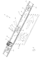
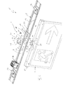
- Fig. 1-4 comprises a light tape element 1 only partially shown a device support 2, to which by means of a fastening device 3, an electrical load 4 is attached.
- the light band element 1 also has a supporting profile, not shown here, on which the device carrier 2 can be fastened and with which the light band element 1 can be mounted on a wall or ceiling.
- the light band element 1 can basically be used as a single luminaire. However, it preferably forms part of a light band consisting of a plurality of light band elements 1.
- the fastening device 3 comprises a cylinder 5, which is fixed, at least rotationally fixed, is arranged on the consumer 4 and having an outer peripheral circumferential groove 6.
- the fastening device 3 also has a through opening 7 formed on the equipment carrier 2, into which the cylinder 5 can be inserted axially until the circumferential groove 6 is located on an inner side 8 of the equipment carrier 2.
- the inside 8 faces away from the consumer 4 or the support profile and in the representations of Fig. 1-4 facing the viewer.
- In the passage opening 7 of the cylinder 5 is arranged relative to the device carrier 2 about a longitudinal central axis 9 of the cylinder 5 rotatably.
- the longitudinal central axis 9 of the cylinder 5 thereby defines an axis of rotation or pivot about which the consumer 4 is adjustable relative to the equipment carrier 2.
- the longitudinal center axis 9 will therefore also be referred to as the cylinder longitudinal central axis 9 or as the pivot axis 9 or as the axis of rotation 9.
- the fastening device 3 also comprises a slider 10, which is arranged on the inner side 8 and engages in the circumferential groove 6 and thereby secures the cylinder 5 with respect to the longitudinal central axis 9 axially on the equipment carrier 2.
- the fastening device 3 is also equipped with a fastening element 11, by means of which a rotational position between the cylinder 5 and slide 10 can be fixed. Furthermore, it is provided here that the slide 10 with respect to the axis of rotation 9 rotatably disposed on the equipment carrier 2. This ensures that the rotational fixation between cylinder 5 and slide 10 ultimately generates a rotational fixation between the cylinder 5 and device carrier 2. Since the consumer 4 is also non-rotatably connected to the cylinder 5, the desired rotational fixation between the consumer 4 and device carrier 2 results.
- the device carrier 2 has in its cross-sectional profile two mutually remote edge regions 12 which have a certain spring elasticity with respect to their spacing direction and form on their opposite outer sides a Klippskontur, with the aid of the device carrier 2 is anklippsbar to the support profile, which has facing each other complementary mating contours ,
- the device carrier 2 can be locked with the carrier profile.
- the device carrier 2 may have at least one, preferably two locking devices 13 with which the device carrier 2 can be locked in a suitable manner to the carrier profile.
- the profile edge regions 12 are expediently shaped or configured on their mutually facing inner sides such that lateral, groove-like longitudinal guides 14 are formed, specifically in each edge region 12 such a longitudinal guide 14.
- the slider 10 engages laterally.
- the longitudinal guides 14 extend parallel to each other, namely along the rectilinear device carrier 2.
- the slider 10 in these longitudinal guides 14 is transverse to the axis of rotation 9 relative to the device carrier 2 adjustable.
- the slider 10 in the longitudinal guides 14 in a direction indicated by a double arrow longitudinal direction 15 of the device carrier 2 is adjustable.
- the slider 10 has a slide recess 16, which is oriented transversely to the axis of rotation 9 or parallel to the longitudinal direction 15 and which is bounded by an edge region 17 of the slider 10.
- the edge region 17 engages in the circumferential groove 6 a.
- the fastening element 11 can now cooperate with this edge region 17 for fixing the rotational position between the cylinder 5 and the slider 10.
- the fastener 11 is designed pin-shaped.
- the fastener 11 is a screw.
- the fastening element 11 penetrates this first opening 18.
- two such first openings 18 are provided which are diametrically opposed to one another, that is to say offset by 180 ° relative to one another.
- this first opening 18 may be designed as a threaded opening.
- a screw fastener 11 with the slider 10, in the edge region 17, axially braced. This results in a frictional or non-positive rotational fixation.
- At least one second opening 19 may be formed on the slider 10, expediently in the edge region 17.
- a plurality of second openings 19 are shown, namely preferably five second openings 19.
- the cylinder 5 axially in alignment with the respective first opening 18 also has a third opening 20 which is formed on a consumer 4 side facing the cylinder 5.
- the respective second opening 19 of the slider 10 is then designed as an axial passage opening, so that the fastening element 11 for fixing the rotational position between the cylinder 5 and slide 10 can engage axially through the respective first opening 18 and through the respectively selected second opening 19 into the respective third opening 20. This results in a particularly effective positive rotation lock.
- the respective first opening 18 can be designed as a threaded opening. Alternatively or additionally, then the respective third opening 20 may be configured as a threaded opening.
- the fastening element 11 is then designed as a screw and can be screwed to the cylinder 5.
- the fastening device 3 presented here also has a contact element 21, which ensures an electrical connection between the device carrier 2 and the slide 10.
- the contact element 21 is suitably made of metal, preferably spring steel.
- the contact element 21 has a central opening 22, through which the cylinder 5 can be inserted axially therethrough. This makes it possible to arrange the contact element 21 with respect to the axis of rotation 9 axially between the device carrier 2 and the slider 10. Accordingly, the contact element 21 is configured comparatively flat. In particular, it is a comparatively thin sheet metal part. Particularly advantageous is the embodiment shown here, in which the contact element 21 is designed as a leaf spring element. In this way, with the aid of the contact element 21 within the fastening device 3, an axial tension between slide 10, device carrier 2 and cylinder 5 can be realized.
- the cylinder 5 is supported on an unspecified outside of the equipment carrier 2 via an annular step 23 axially on the equipment carrier 2 from. Said outside of the equipment carrier 2 is facing the consumer 4 and facing away from the support profile.
- the contact element 21 on a device carrier 2 side facing several cutting edges or cutting tips 24 which are configured so that they penetrate an optionally existing paint finish of the device carrier 2 during assembly of the fastening device 3.
- equipment carrier 2, cylinder 5, slide 10 and contact element 21 are made of metal, so that ultimately via the contact element 21 of the cylinder 5 is electrically connected to the equipment carrier 2.
- the consumer 4 in the example shown is an illuminated sign, namely an emergency exit sign or escape route sign.
- the consumer 4 may also be a luminaire, in particular a spotlight.
- the cylinder 5 is hollow and has a central passage 25 through which electrical leads 4 of the load 4, not shown, can be passed. As a result, these lines can be passed through the passage 25 to the inside 8 of the device carrier 2, for example, to connect them electrically to a current collector 26, which is contacted when mounting the device carrier 2 on the support section, for example, with a laid in the support profile power guide rail.
- the consumer 4 may have an electrical protective conductor, for example, to ground a metallic carrier 27 or a housing of the consumer 4.
- the cylinder 5 is expediently designed to be electrically conductive and electrically connected to this protective conductor or to the carrier 27.
- the grounding of the consumer 4 with the grounding of the device carrier 2 are electrically connected.
- the slide recess 16 may be configured, for example, U-shaped. On its open side, it can have inlet slopes 28.
- FIGS. 1 and 2 the consumer 4 is aligned parallel to the equipment carrier 2.
- the consumer is 4 in the Figures 3 and 4 aligned transversely to the device carrier 2.
- the slider 10 is rotatably mounted on the equipment carrier 2.
- the rotational fixation of the slider 10 relative to the equipment carrier 2 is effected in particular by its lateral engagement in the two parallel longitudinal guides 14.
- the slider 10 may have an angled edge portion 29, which is the force introduction for adjusting the slider 10 simplified.
- the contact element 21 While the cutting tips 24 protrude from the contact element 21 on the side facing the device carrier 2, the contact element 21 also has at least one contact tip 30, which protrudes on the opposite side, ie on the side facing the slider 10, to the electrical contact with the slider 10th to improve.
Landscapes
- Engineering & Computer Science (AREA)
- General Engineering & Computer Science (AREA)
- Physics & Mathematics (AREA)
- General Physics & Mathematics (AREA)
- Theoretical Computer Science (AREA)
- Clamps And Clips (AREA)
- Fastening Of Light Sources Or Lamp Holders (AREA)
Applications Claiming Priority (1)
| Application Number | Priority Date | Filing Date | Title |
|---|---|---|---|
| DE202010009487U DE202010009487U1 (de) | 2010-06-24 | 2010-06-24 | Befestigungsvorrichtung |
Publications (3)
| Publication Number | Publication Date |
|---|---|
| EP2400207A2 true EP2400207A2 (fr) | 2011-12-28 |
| EP2400207A3 EP2400207A3 (fr) | 2013-01-23 |
| EP2400207B1 EP2400207B1 (fr) | 2016-09-28 |
Family
ID=42932960
Family Applications (1)
| Application Number | Title | Priority Date | Filing Date |
|---|---|---|---|
| EP11170086.0A Active EP2400207B1 (fr) | 2010-06-24 | 2011-06-16 | Dispositif de fixation |
Country Status (3)
| Country | Link |
|---|---|
| EP (1) | EP2400207B1 (fr) |
| DE (1) | DE202010009487U1 (fr) |
| PL (1) | PL2400207T3 (fr) |
Cited By (2)
| Publication number | Priority date | Publication date | Assignee | Title |
|---|---|---|---|---|
| CN103377596A (zh) * | 2012-04-20 | 2013-10-30 | 海洋王(东莞)照明科技有限公司 | 标志灯 |
| KR20230147331A (ko) * | 2022-04-14 | 2023-10-23 | 이경철 | 엘이디 등기구의 천장 결합장치 |
Families Citing this family (7)
| Publication number | Priority date | Publication date | Assignee | Title |
|---|---|---|---|---|
| SE536724C2 (sv) * | 2011-02-14 | 2014-06-24 | Bo Fastening Ab | Fästanordning för upphängning av skyltar |
| DE202012101249U1 (de) | 2012-04-05 | 2013-07-09 | Zumtobel Lighting Gmbh | Haltevorrichtung zur Halterung einer Hinweisleuchte an einer Tragschiene |
| DE102016013374B4 (de) * | 2016-03-10 | 2019-11-21 | Rzb Rudolf Zimmermann, Bamberg Gmbh | Universelle Befestigungsvorrichtung für Beleuchtungseinrichtungen |
| FR3114140B1 (fr) * | 2020-09-15 | 2023-04-28 | Legrand France | Bloc autonome de sécurité |
| EP4241018B1 (fr) * | 2020-11-03 | 2024-10-16 | Signify Holding B.V. | Module adaptateur encliquetable sans outil pour l'intégration de luminaires à tête de projecteur |
| DE102023125459A1 (de) * | 2023-09-20 | 2025-03-20 | Zumtobel Lighting Gmbh | Haltevorrichtung zur drehbaren halterung eines bauteils an einer tragschiene |
| DE102024100353B4 (de) * | 2024-01-08 | 2025-08-07 | Oktalite Lichttechnik GmbH | Leuchte mit verriegelbarem Befestigungsabgriff und Verfahren zur Montage einer Leuchte |
Family Cites Families (4)
| Publication number | Priority date | Publication date | Assignee | Title |
|---|---|---|---|---|
| US5063481A (en) * | 1990-10-15 | 1991-11-05 | Eaton Corporation | Pivot assembly for vehicle headlight position adjustment |
| JPH08180728A (ja) * | 1994-12-21 | 1996-07-12 | Tec Corp | 照明器具 |
| DE19859400C2 (de) * | 1998-12-22 | 2001-09-13 | Murjahn Kg Vlm | Vorrichtung zur Befestigung eines Leuchtenkopfs einer Strahlerleuchte an einem Träger |
| DE20021640U1 (de) * | 1999-12-21 | 2001-03-29 | Stelling, Reiner, 27432 Bremervörde | Schnellbefestigungssystem für Rohre zur Verwendung im Bereich der Licht- und Tontechnik |
-
2010
- 2010-06-24 DE DE202010009487U patent/DE202010009487U1/de not_active Expired - Lifetime
-
2011
- 2011-06-16 PL PL11170086T patent/PL2400207T3/pl unknown
- 2011-06-16 EP EP11170086.0A patent/EP2400207B1/fr active Active
Non-Patent Citations (1)
| Title |
|---|
| None |
Cited By (2)
| Publication number | Priority date | Publication date | Assignee | Title |
|---|---|---|---|---|
| CN103377596A (zh) * | 2012-04-20 | 2013-10-30 | 海洋王(东莞)照明科技有限公司 | 标志灯 |
| KR20230147331A (ko) * | 2022-04-14 | 2023-10-23 | 이경철 | 엘이디 등기구의 천장 결합장치 |
Also Published As
| Publication number | Publication date |
|---|---|
| PL2400207T3 (pl) | 2017-02-28 |
| EP2400207A3 (fr) | 2013-01-23 |
| DE202010009487U1 (de) | 2010-10-07 |
| EP2400207B1 (fr) | 2016-09-28 |
Similar Documents
| Publication | Publication Date | Title |
|---|---|---|
| EP2400207B1 (fr) | Dispositif de fixation | |
| EP1016821B1 (fr) | Chemin d' éclairage avec un profil support fixable à un mur ou à un plafond | |
| DE2320983A1 (de) | Einspeise- bzw. abnehmevorrichtung fuer stromschienen | |
| EP2091111B1 (fr) | Système de contact pour bandes lumineuses ou lampes | |
| EP1916740A1 (fr) | Commutateur d'installation et borne par serrage pour un commutateur d'installation | |
| WO2021069296A1 (fr) | Luminaire ou unité électrique pour raccordement à un rail de support | |
| EP2556568B1 (fr) | Adaptateur à un rail conducteur | |
| DE202021107024U1 (de) | Verstellbarer Kabelbefestigungshalter | |
| EP4181326B1 (fr) | Élément de contact pour connecter un module électrique ou électronique à un rail de support de luminaire allongé | |
| EP0291989A1 (fr) | Barre omnibus à basse tension | |
| EP2019259B1 (fr) | Système de liaison pour rails de support d'éléments d'éclairage d'une bande de lumière | |
| EP3856568A1 (fr) | Raccord de dilatation pour une ligne de contact et ligne de contact | |
| DE102013213786A1 (de) | Leuchte | |
| DE202010015292U1 (de) | Kupplungselement mit Erdungsfunktion | |
| DE3817133C2 (fr) | ||
| DE102023104652A1 (de) | Berührungsschutzabdeckung, Anschlussteil und Modulverbinder | |
| EP4042524A1 (fr) | Rail porteur et système de rail porteur doté de rails porteurs | |
| EP1361632B1 (fr) | Elément de support pour contact élastique | |
| DE202024104710U1 (de) | Verbinder zur mechanischen Verbindung eines Leuchtenbetriebsgeräts mit einem länglichen Leuchtenträger | |
| DE3721679A1 (de) | Steckanschluss | |
| DE102023122124A1 (de) | System zur Befestigung mindestens eines elektrischen Funktionselementes | |
| EP1840452A1 (fr) | Ensemble d'éclairage | |
| DE19904949C1 (de) | Abgangsschienenträger zum Einbau in eine elektrische Verteilanlage | |
| DE102021112403A1 (de) | Elektrisches Modul zum Anschließen an eine Tragschiene | |
| DE3241125C2 (de) | Befestigungsvorrichtung für Schalter oder sonstige, in Anlagen nachträglich funktionslagegerecht zu montierende Bauteile |
Legal Events
| Date | Code | Title | Description |
|---|---|---|---|
| AK | Designated contracting states |
Kind code of ref document: A2 Designated state(s): AL AT BE BG CH CY CZ DE DK EE ES FI FR GB GR HR HU IE IS IT LI LT LU LV MC MK MT NL NO PL PT RO RS SE SI SK SM TR |
|
| AX | Request for extension of the european patent |
Extension state: BA ME |
|
| PUAI | Public reference made under article 153(3) epc to a published international application that has entered the european phase |
Free format text: ORIGINAL CODE: 0009012 |
|
| PUAL | Search report despatched |
Free format text: ORIGINAL CODE: 0009013 |
|
| AK | Designated contracting states |
Kind code of ref document: A3 Designated state(s): AL AT BE BG CH CY CZ DE DK EE ES FI FR GB GR HR HU IE IS IT LI LT LU LV MC MK MT NL NO PL PT RO RS SE SI SK SM TR |
|
| AX | Request for extension of the european patent |
Extension state: BA ME |
|
| RIC1 | Information provided on ipc code assigned before grant |
Ipc: F21V 21/02 20060101ALI20121220BHEP Ipc: F21S 2/00 20060101AFI20121220BHEP Ipc: G09F 7/20 20060101ALI20121220BHEP |
|
| 17P | Request for examination filed |
Effective date: 20130626 |
|
| RBV | Designated contracting states (corrected) |
Designated state(s): AL AT BE BG CH CY CZ DE DK EE ES FI FR GB GR HR HU IE IS IT LI LT LU LV MC MK MT NL NO PL PT RO RS SE SI SK SM TR |
|
| 17Q | First examination report despatched |
Effective date: 20150618 |
|
| REG | Reference to a national code |
Ref country code: DE Ref legal event code: R079 Ref document number: 502011010771 Country of ref document: DE Free format text: PREVIOUS MAIN CLASS: F21S0002000000 Ipc: F21V0017180000 |
|
| RIC1 | Information provided on ipc code assigned before grant |
Ipc: F21Y 103/00 20160101ALI20160315BHEP Ipc: F21V 21/02 20060101ALI20160315BHEP Ipc: G09F 7/20 20060101ALI20160315BHEP Ipc: F21S 2/00 20160101ALI20160315BHEP Ipc: F21Y 113/00 20160101ALI20160315BHEP Ipc: F21V 17/18 20060101AFI20160315BHEP Ipc: F21Y 101/00 20160101ALI20160315BHEP |
|
| GRAP | Despatch of communication of intention to grant a patent |
Free format text: ORIGINAL CODE: EPIDOSNIGR1 |
|
| INTG | Intention to grant announced |
Effective date: 20160511 |
|
| GRAS | Grant fee paid |
Free format text: ORIGINAL CODE: EPIDOSNIGR3 |
|
| GRAA | (expected) grant |
Free format text: ORIGINAL CODE: 0009210 |
|
| AK | Designated contracting states |
Kind code of ref document: B1 Designated state(s): AL AT BE BG CH CY CZ DE DK EE ES FI FR GB GR HR HU IE IS IT LI LT LU LV MC MK MT NL NO PL PT RO RS SE SI SK SM TR |
|
| REG | Reference to a national code |
Ref country code: GB Ref legal event code: FG4D Free format text: NOT ENGLISH |
|
| REG | Reference to a national code |
Ref country code: CH Ref legal event code: EP |
|
| REG | Reference to a national code |
Ref country code: AT Ref legal event code: REF Ref document number: 833095 Country of ref document: AT Kind code of ref document: T Effective date: 20161015 |
|
| REG | Reference to a national code |
Ref country code: IE Ref legal event code: FG4D Free format text: LANGUAGE OF EP DOCUMENT: GERMAN |
|
| REG | Reference to a national code |
Ref country code: DE Ref legal event code: R096 Ref document number: 502011010771 Country of ref document: DE |
|
| REG | Reference to a national code |
Ref country code: LT Ref legal event code: MG4D |
|
| PG25 | Lapsed in a contracting state [announced via postgrant information from national office to epo] |
Ref country code: LT Free format text: LAPSE BECAUSE OF FAILURE TO SUBMIT A TRANSLATION OF THE DESCRIPTION OR TO PAY THE FEE WITHIN THE PRESCRIBED TIME-LIMIT Effective date: 20160928 Ref country code: NO Free format text: LAPSE BECAUSE OF FAILURE TO SUBMIT A TRANSLATION OF THE DESCRIPTION OR TO PAY THE FEE WITHIN THE PRESCRIBED TIME-LIMIT Effective date: 20161228 Ref country code: RS Free format text: LAPSE BECAUSE OF FAILURE TO SUBMIT A TRANSLATION OF THE DESCRIPTION OR TO PAY THE FEE WITHIN THE PRESCRIBED TIME-LIMIT Effective date: 20160928 Ref country code: HR Free format text: LAPSE BECAUSE OF FAILURE TO SUBMIT A TRANSLATION OF THE DESCRIPTION OR TO PAY THE FEE WITHIN THE PRESCRIBED TIME-LIMIT Effective date: 20160928 Ref country code: FI Free format text: LAPSE BECAUSE OF FAILURE TO SUBMIT A TRANSLATION OF THE DESCRIPTION OR TO PAY THE FEE WITHIN THE PRESCRIBED TIME-LIMIT Effective date: 20160928 |
|
| REG | Reference to a national code |
Ref country code: NL Ref legal event code: MP Effective date: 20160928 |
|
| PG25 | Lapsed in a contracting state [announced via postgrant information from national office to epo] |
Ref country code: SE Free format text: LAPSE BECAUSE OF FAILURE TO SUBMIT A TRANSLATION OF THE DESCRIPTION OR TO PAY THE FEE WITHIN THE PRESCRIBED TIME-LIMIT Effective date: 20160928 Ref country code: NL Free format text: LAPSE BECAUSE OF FAILURE TO SUBMIT A TRANSLATION OF THE DESCRIPTION OR TO PAY THE FEE WITHIN THE PRESCRIBED TIME-LIMIT Effective date: 20160928 Ref country code: GR Free format text: LAPSE BECAUSE OF FAILURE TO SUBMIT A TRANSLATION OF THE DESCRIPTION OR TO PAY THE FEE WITHIN THE PRESCRIBED TIME-LIMIT Effective date: 20161229 Ref country code: LV Free format text: LAPSE BECAUSE OF FAILURE TO SUBMIT A TRANSLATION OF THE DESCRIPTION OR TO PAY THE FEE WITHIN THE PRESCRIBED TIME-LIMIT Effective date: 20160928 |
|
| PG25 | Lapsed in a contracting state [announced via postgrant information from national office to epo] |
Ref country code: EE Free format text: LAPSE BECAUSE OF FAILURE TO SUBMIT A TRANSLATION OF THE DESCRIPTION OR TO PAY THE FEE WITHIN THE PRESCRIBED TIME-LIMIT Effective date: 20160928 Ref country code: RO Free format text: LAPSE BECAUSE OF FAILURE TO SUBMIT A TRANSLATION OF THE DESCRIPTION OR TO PAY THE FEE WITHIN THE PRESCRIBED TIME-LIMIT Effective date: 20160928 |
|
| PG25 | Lapsed in a contracting state [announced via postgrant information from national office to epo] |
Ref country code: CZ Free format text: LAPSE BECAUSE OF FAILURE TO SUBMIT A TRANSLATION OF THE DESCRIPTION OR TO PAY THE FEE WITHIN THE PRESCRIBED TIME-LIMIT Effective date: 20160928 Ref country code: SK Free format text: LAPSE BECAUSE OF FAILURE TO SUBMIT A TRANSLATION OF THE DESCRIPTION OR TO PAY THE FEE WITHIN THE PRESCRIBED TIME-LIMIT Effective date: 20160928 Ref country code: PT Free format text: LAPSE BECAUSE OF FAILURE TO SUBMIT A TRANSLATION OF THE DESCRIPTION OR TO PAY THE FEE WITHIN THE PRESCRIBED TIME-LIMIT Effective date: 20170130 Ref country code: IS Free format text: LAPSE BECAUSE OF FAILURE TO SUBMIT A TRANSLATION OF THE DESCRIPTION OR TO PAY THE FEE WITHIN THE PRESCRIBED TIME-LIMIT Effective date: 20170128 Ref country code: BG Free format text: LAPSE BECAUSE OF FAILURE TO SUBMIT A TRANSLATION OF THE DESCRIPTION OR TO PAY THE FEE WITHIN THE PRESCRIBED TIME-LIMIT Effective date: 20161228 Ref country code: SM Free format text: LAPSE BECAUSE OF FAILURE TO SUBMIT A TRANSLATION OF THE DESCRIPTION OR TO PAY THE FEE WITHIN THE PRESCRIBED TIME-LIMIT Effective date: 20160928 Ref country code: ES Free format text: LAPSE BECAUSE OF FAILURE TO SUBMIT A TRANSLATION OF THE DESCRIPTION OR TO PAY THE FEE WITHIN THE PRESCRIBED TIME-LIMIT Effective date: 20160928 |
|
| REG | Reference to a national code |
Ref country code: FR Ref legal event code: PLFP Year of fee payment: 7 Ref country code: DE Ref legal event code: R097 Ref document number: 502011010771 Country of ref document: DE |
|
| PG25 | Lapsed in a contracting state [announced via postgrant information from national office to epo] |
Ref country code: IT Free format text: LAPSE BECAUSE OF FAILURE TO SUBMIT A TRANSLATION OF THE DESCRIPTION OR TO PAY THE FEE WITHIN THE PRESCRIBED TIME-LIMIT Effective date: 20160928 |
|
| PG25 | Lapsed in a contracting state [announced via postgrant information from national office to epo] |
Ref country code: DK Free format text: LAPSE BECAUSE OF FAILURE TO SUBMIT A TRANSLATION OF THE DESCRIPTION OR TO PAY THE FEE WITHIN THE PRESCRIBED TIME-LIMIT Effective date: 20160928 |
|
| PLBE | No opposition filed within time limit |
Free format text: ORIGINAL CODE: 0009261 |
|
| STAA | Information on the status of an ep patent application or granted ep patent |
Free format text: STATUS: NO OPPOSITION FILED WITHIN TIME LIMIT |
|
| 26N | No opposition filed |
Effective date: 20170629 |
|
| PG25 | Lapsed in a contracting state [announced via postgrant information from national office to epo] |
Ref country code: SI Free format text: LAPSE BECAUSE OF FAILURE TO SUBMIT A TRANSLATION OF THE DESCRIPTION OR TO PAY THE FEE WITHIN THE PRESCRIBED TIME-LIMIT Effective date: 20160928 |
|
| PG25 | Lapsed in a contracting state [announced via postgrant information from national office to epo] |
Ref country code: MC Free format text: LAPSE BECAUSE OF FAILURE TO SUBMIT A TRANSLATION OF THE DESCRIPTION OR TO PAY THE FEE WITHIN THE PRESCRIBED TIME-LIMIT Effective date: 20160928 |
|
| REG | Reference to a national code |
Ref country code: CH Ref legal event code: PL |
|
| REG | Reference to a national code |
Ref country code: IE Ref legal event code: MM4A |
|
| PG25 | Lapsed in a contracting state [announced via postgrant information from national office to epo] |
Ref country code: CH Free format text: LAPSE BECAUSE OF NON-PAYMENT OF DUE FEES Effective date: 20170630 Ref country code: LU Free format text: LAPSE BECAUSE OF NON-PAYMENT OF DUE FEES Effective date: 20170616 Ref country code: LI Free format text: LAPSE BECAUSE OF NON-PAYMENT OF DUE FEES Effective date: 20170630 Ref country code: IE Free format text: LAPSE BECAUSE OF NON-PAYMENT OF DUE FEES Effective date: 20170616 |
|
| REG | Reference to a national code |
Ref country code: BE Ref legal event code: MM Effective date: 20170630 |
|
| REG | Reference to a national code |
Ref country code: FR Ref legal event code: PLFP Year of fee payment: 8 |
|
| REG | Reference to a national code |
Ref country code: AT Ref legal event code: MM01 Ref document number: 833095 Country of ref document: AT Kind code of ref document: T Effective date: 20170616 |
|
| PG25 | Lapsed in a contracting state [announced via postgrant information from national office to epo] |
Ref country code: BE Free format text: LAPSE BECAUSE OF NON-PAYMENT OF DUE FEES Effective date: 20170630 |
|
| PG25 | Lapsed in a contracting state [announced via postgrant information from national office to epo] |
Ref country code: MT Free format text: LAPSE BECAUSE OF FAILURE TO SUBMIT A TRANSLATION OF THE DESCRIPTION OR TO PAY THE FEE WITHIN THE PRESCRIBED TIME-LIMIT Effective date: 20160928 |
|
| PG25 | Lapsed in a contracting state [announced via postgrant information from national office to epo] |
Ref country code: AL Free format text: LAPSE BECAUSE OF FAILURE TO SUBMIT A TRANSLATION OF THE DESCRIPTION OR TO PAY THE FEE WITHIN THE PRESCRIBED TIME-LIMIT Effective date: 20160928 |
|
| PG25 | Lapsed in a contracting state [announced via postgrant information from national office to epo] |
Ref country code: AT Free format text: LAPSE BECAUSE OF NON-PAYMENT OF DUE FEES Effective date: 20170616 |
|
| PG25 | Lapsed in a contracting state [announced via postgrant information from national office to epo] |
Ref country code: HU Free format text: LAPSE BECAUSE OF FAILURE TO SUBMIT A TRANSLATION OF THE DESCRIPTION OR TO PAY THE FEE WITHIN THE PRESCRIBED TIME-LIMIT; INVALID AB INITIO Effective date: 20110616 |
|
| PG25 | Lapsed in a contracting state [announced via postgrant information from national office to epo] |
Ref country code: CY Free format text: LAPSE BECAUSE OF NON-PAYMENT OF DUE FEES Effective date: 20160928 |
|
| PG25 | Lapsed in a contracting state [announced via postgrant information from national office to epo] |
Ref country code: MK Free format text: LAPSE BECAUSE OF FAILURE TO SUBMIT A TRANSLATION OF THE DESCRIPTION OR TO PAY THE FEE WITHIN THE PRESCRIBED TIME-LIMIT Effective date: 20160928 |
|
| PG25 | Lapsed in a contracting state [announced via postgrant information from national office to epo] |
Ref country code: TR Free format text: LAPSE BECAUSE OF FAILURE TO SUBMIT A TRANSLATION OF THE DESCRIPTION OR TO PAY THE FEE WITHIN THE PRESCRIBED TIME-LIMIT Effective date: 20160928 |
|
| PGFP | Annual fee paid to national office [announced via postgrant information from national office to epo] |
Ref country code: PL Payment date: 20250523 Year of fee payment: 15 Ref country code: DE Payment date: 20250626 Year of fee payment: 15 |
|
| PGFP | Annual fee paid to national office [announced via postgrant information from national office to epo] |
Ref country code: GB Payment date: 20250617 Year of fee payment: 15 |
|
| PGFP | Annual fee paid to national office [announced via postgrant information from national office to epo] |
Ref country code: FR Payment date: 20250624 Year of fee payment: 15 |