EP2400208A2 - Eclairage de voie pour piétons - Google Patents
Eclairage de voie pour piétons Download PDFInfo
- Publication number
- EP2400208A2 EP2400208A2 EP11004650A EP11004650A EP2400208A2 EP 2400208 A2 EP2400208 A2 EP 2400208A2 EP 11004650 A EP11004650 A EP 11004650A EP 11004650 A EP11004650 A EP 11004650A EP 2400208 A2 EP2400208 A2 EP 2400208A2
- Authority
- EP
- European Patent Office
- Prior art keywords
- handrail
- lighting
- groups
- lighting means
- pavement
- Prior art date
- Legal status (The legal status is an assumption and is not a legal conclusion. Google has not performed a legal analysis and makes no representation as to the accuracy of the status listed.)
- Granted
Links
Images


Classifications
-
- E—FIXED CONSTRUCTIONS
- E04—BUILDING
- E04F—FINISHING WORK ON BUILDINGS, e.g. STAIRS, FLOORS
- E04F11/00—Stairways, ramps, or like structures; Balustrades; Handrails
- E04F11/18—Balustrades; Handrails
- E04F11/1802—Handrails mounted on walls, e.g. on the wall side of stairs
-
- F—MECHANICAL ENGINEERING; LIGHTING; HEATING; WEAPONS; BLASTING
- F21—LIGHTING
- F21S—NON-PORTABLE LIGHTING DEVICES; SYSTEMS THEREOF; VEHICLE LIGHTING DEVICES SPECIALLY ADAPTED FOR VEHICLE EXTERIORS
- F21S4/00—Lighting devices or systems using a string or strip of light sources
- F21S4/10—Lighting devices or systems using a string or strip of light sources with light sources attached to loose electric cables, e.g. Christmas tree lights
-
- F—MECHANICAL ENGINEERING; LIGHTING; HEATING; WEAPONS; BLASTING
- F21—LIGHTING
- F21S—NON-PORTABLE LIGHTING DEVICES; SYSTEMS THEREOF; VEHICLE LIGHTING DEVICES SPECIALLY ADAPTED FOR VEHICLE EXTERIORS
- F21S4/00—Lighting devices or systems using a string or strip of light sources
- F21S4/20—Lighting devices or systems using a string or strip of light sources with light sources held by or within elongate supports
-
- F—MECHANICAL ENGINEERING; LIGHTING; HEATING; WEAPONS; BLASTING
- F21—LIGHTING
- F21V—FUNCTIONAL FEATURES OR DETAILS OF LIGHTING DEVICES OR SYSTEMS THEREOF; STRUCTURAL COMBINATIONS OF LIGHTING DEVICES WITH OTHER ARTICLES, NOT OTHERWISE PROVIDED FOR
- F21V23/00—Arrangement of electric circuit elements in or on lighting devices
-
- E—FIXED CONSTRUCTIONS
- E04—BUILDING
- E04F—FINISHING WORK ON BUILDINGS, e.g. STAIRS, FLOORS
- E04F11/00—Stairways, ramps, or like structures; Balustrades; Handrails
- E04F11/18—Balustrades; Handrails
- E04F2011/1868—Miscellaneous features of handrails not otherwise provided for
- E04F2011/1872—Miscellaneous features of handrails not otherwise provided for illuminated
-
- F—MECHANICAL ENGINEERING; LIGHTING; HEATING; WEAPONS; BLASTING
- F21—LIGHTING
- F21S—NON-PORTABLE LIGHTING DEVICES; SYSTEMS THEREOF; VEHICLE LIGHTING DEVICES SPECIALLY ADAPTED FOR VEHICLE EXTERIORS
- F21S8/00—Lighting devices intended for fixed installation
- F21S8/03—Lighting devices intended for fixed installation of surface-mounted type
- F21S8/033—Lighting devices intended for fixed installation of surface-mounted type the surface being a wall or like vertical structure, e.g. building facade
- F21S8/036—Lighting devices intended for fixed installation of surface-mounted type the surface being a wall or like vertical structure, e.g. building facade by means of a rigid support, e.g. bracket or arm
-
- F—MECHANICAL ENGINEERING; LIGHTING; HEATING; WEAPONS; BLASTING
- F21—LIGHTING
- F21W—INDEXING SCHEME ASSOCIATED WITH SUBCLASSES F21K, F21L, F21S and F21V, RELATING TO USES OR APPLICATIONS OF LIGHTING DEVICES OR SYSTEMS
- F21W2111/00—Use or application of lighting devices or systems for signalling, marking or indicating, not provided for in codes F21W2102/00 – F21W2107/00
- F21W2111/02—Use or application of lighting devices or systems for signalling, marking or indicating, not provided for in codes F21W2102/00 – F21W2107/00 for roads, paths or the like
- F21W2111/023—Use or application of lighting devices or systems for signalling, marking or indicating, not provided for in codes F21W2102/00 – F21W2107/00 for roads, paths or the like for pedestrian walkways
-
- F—MECHANICAL ENGINEERING; LIGHTING; HEATING; WEAPONS; BLASTING
- F21—LIGHTING
- F21W—INDEXING SCHEME ASSOCIATED WITH SUBCLASSES F21K, F21L, F21S and F21V, RELATING TO USES OR APPLICATIONS OF LIGHTING DEVICES OR SYSTEMS
- F21W2111/00—Use or application of lighting devices or systems for signalling, marking or indicating, not provided for in codes F21W2102/00 – F21W2107/00
- F21W2111/08—Use or application of lighting devices or systems for signalling, marking or indicating, not provided for in codes F21W2102/00 – F21W2107/00 for handles or handrails
-
- F—MECHANICAL ENGINEERING; LIGHTING; HEATING; WEAPONS; BLASTING
- F21—LIGHTING
- F21W—INDEXING SCHEME ASSOCIATED WITH SUBCLASSES F21K, F21L, F21S and F21V, RELATING TO USES OR APPLICATIONS OF LIGHTING DEVICES OR SYSTEMS
- F21W2131/00—Use or application of lighting devices or systems not provided for in codes F21W2102/00-F21W2121/00
- F21W2131/10—Outdoor lighting
- F21W2131/101—Outdoor lighting of tunnels or the like, e.g. under bridges
-
- F—MECHANICAL ENGINEERING; LIGHTING; HEATING; WEAPONS; BLASTING
- F21—LIGHTING
- F21Y—INDEXING SCHEME ASSOCIATED WITH SUBCLASSES F21K, F21L, F21S and F21V, RELATING TO THE FORM OR THE KIND OF THE LIGHT SOURCES OR OF THE COLOUR OF THE LIGHT EMITTED
- F21Y2115/00—Light-generating elements of semiconductor light sources
- F21Y2115/10—Light-emitting diodes [LED]
Definitions
- the invention relates to a walkway lighting with arranged in or on a handrail lights with bulbs, especially LEDs, of which with a respective distribution of illuminance, each having a maximum in the region of a main emission of the light emitted by a respective light source, a walkway illuminated is, wherein the lighting means are spaced relative to the longitudinal direction of the handrail.
- Pavement lighting is used, for example, as safety and orientation lighting for walkways in tunnels such as railway tunnels.
- a mechanically stable, continuous handrail is mounted on the tunnel walls in each railway tunnel. It is known to install in this handrail walkway lighting, which provides for maintenance work and necessary evacuations through the tunnel for greater safety of the emergency personnel and customers.
- a continuous light band is used in a groove formed on the underside of the handrail, which has LEDs that form the bulbs of the walkway lighting.
- shorter light band sections are used, wherein in each case a distance is provided between two such light band sections, which follow one another in the longitudinal direction of the handrail.
- the bulbs formed by the LEDs are arranged in relatively small distances, usually at a distance of 10mm to 150mm, along the light band.
- there is an unlit portion of the sidewalk which is more or less long depending on the length of the light band.
- the object of the invention is to provide an improved walkway lighting of the type mentioned. According to the invention, this is achieved by a pavement lighting with the features of claim 1.
- At least two groups of light sources are present.
- Each of these groups comprises a plurality of bulbs and is powered by its own supply unit with electrical energy.
- the handrail lamps of different groups alternate each other. If, in a respective section of the longitudinal extent of the handrail, such a section may for example have a length in the range of 20m to 50m, two groups of bulbs are present, which is preferred, bulbs of the first group and the second group thus alternately (alternately ) to each other.
- every second luminous means arranged along the handrail will shine. It can still be provided by a gapless lighting or lighting the walkway with only short gaps.
- each of the at least one other group caused by two illuminants of each other in the longitudinal direction of the handrail preferably overlap those areas within which the illuminance of the respective light source is at most 3%, preferably has fallen to at most 5%, more preferably to at most 10% of the maximum.
- the areas of illuminance, within which the illuminance of the respective bulb has fallen to at most 3%, preferably at most 5%, more preferably at most 10% of the maximum It can thereby be maintained even in case of failure of one of the groups a minimum illuminance along the entire walkway.
- the main emission directions are inclined in opposite directions for lamps sequential in the longitudinal direction of the handrail with respect to the vertical. If two groups of light sources are present, the main emission directions of one group are thus inclined in one direction with respect to the vertical and the main emission directions of the other group with respect to the vertical in the other direction.
- each of the lamps is arranged in a respective own housing and a respective lamp thus has a single lamp, or there are two adjacent lamps arranged in a common housing, so that a respective lamp has two lamps.
- the training with a small number of points of light creates less effort in cleaning.
- the assembly costs and maintenance costs can be reduced.
- the lighting means of a respective group are advantageously connected in series.
- Each of the groups advantageously comprises more than five bulbs.
- the bulbs of the pavement lighting so at least for all bulbs apart from the two edge bulbs at the two ends of the handrail, that the bulbs are arranged in pairs in or on the handrail, of a respective Pair of one of the lamps to the first and one of the lamps belonging to the second group and the distance between the lamps of each pair is less than a third, preferably less than a sixth of the distance between two longitudinally of the handrail successive pairs.
- the main radiation directions of the two lamps of a respective pair relative to the vertical are inclined in opposite directions (seen in a horizontal view perpendicular to the longitudinal extent of the handrail), the main radiation directions diverge downwards, ie towards the sidewalk.
- the two lamps of a respective pair may in this case be arranged in a respective separate housing, wherein two separate lamps are formed, or arranged to form a single lamp in a common housing.
- the electrical connection of the lighting means may comprise four-pole connecting cables, which have four-pole connectors at both ends. Between the connection cables Auskoppelstecküen be used. These have first and second four-pin connectors for connection to the four-pin connectors of the two connection cables. Furthermore, the decoupling plug-in units, if each of the lighting means is arranged in a separate housing, third and fourth plug, which are formed bipolar and which serve for connection to the two lamps of a respective pair.
- a four-pole plug could also be provided which is plugged into a four-pole plug of the housing for connection to the two light sources. It can be formed in this way a modular design.
- the handrail 2 is fastened to a wall, for example a tunnel wall, for example by means of holders 4 spaced apart in the longitudinal direction 8 of the handrail.
- a wall for example a tunnel wall
- support posts could be provided, where the handrail 2 is fixed by means of brackets.
- the handrail 2 with the serving for fixing the handrail 2 parts forms a railing.
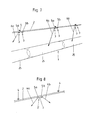
- the lights 3 each have a light source 5a, 5b, the in Fig. 1 each indicated by a dot.
- the lighting means 5a, 5b radiate in the direction of the walkway 1, wherein the main emission directions 6a, 6b are indicated by arrows.
- a respective illuminant serves to illuminate the walkway 1 with a respective distribution of illuminance. This illuminance has its maximum in the region in which the main emission direction 6a, 6b passes through the plane of the sidewalk 1.
- the main radiation directions 6a, 6b and the distributions of the illuminance are determined by the distribution of the light emitted by the light sources 5a, 5b, by optical elements for the light guidance of the light 3 and by the arrangement of the respective light 3.
- the luminaire comprises a housing 7, for example made of a transparent material. Inside the housing, an LED is arranged as the lighting means 5a, 5b. The LED is held by a board 9, which further carries an optical system 10 for guiding the light emitted by the LED light. The emitted light passes through a light exit surface 11. In any case, the light exit surface 11 is transparent.
- the connection cable is in for simplicity Fig. 2 not shown.
- a strain relief 12 is used to strain relief of the connection cable. In the area of the strain relief device 12, a seal is also provided for the sealed passage of the connection cable.
- the housing 7 further comprises elastic locking elements 13a, 13b. These are used for snap mounting in a arranged on the underside of the handrail 2 in this groove 14.
- the elastic locking elements are here formed by two elastic webs or wings, which can be snapped into the groove. Other types of locking latches are conceivable and possible.
- the arrangement of a respective lamp 3 in the handrail 2 is from the 3 and 4 seen.
- the luminaires 3 with the lighting means 5a, 5b are arranged in pairs relative to the longitudinal direction 8 of the handrail 2, i. There are two lights 3 with bulbs 5a and 5b, respectively, at a small distance from each other, while the distance to the next pair of lights 3 with bulbs 5a, 5b is substantially larger, preferably more than 3 times as large, more preferably more than 6 times as big.
- the distance a between two lamps of a respective pair can be in the range of 5 cm to 20 cm, while the distance A between the lamps of a pair spaced apart is in the range of 1-2.5 m.
- a respective pair of luminaires 3 with illuminating means 5a, 5b is arranged at a respective holder 4.
- a light 3 is arranged with a light source 5a and 5b, and directly after the holder 4 or at a distance from this.
- the height of the handrail 2 above the walkway 1 having horizontal plane is in the range of 90cm +/- 20cm.
- One or more holders 4 could also lie between a pair arranged in the region of a holder 4, in areas of which no pair of lamps is arranged.
- the pairs of bulbs could also be arranged in areas of the handrail 2 lying between successive brackets 4, e.g. each centrally between two consecutive brackets 4. It could also be provided individual lights 3, each having a pair of lighting means 5a, 5b.
- the main emission directions 6a, 6b of the two light sources 5a, 5b of a respective pair are viewed in a horizontal view at right angles to the longitudinal extension of the handrail 2 (in a view corresponding to FIG Fig. 3 ) are inclined relative to the vertical in opposite directions, such that the main emission directions 6a, 6b diverge downwards, ie towards the sidewalk 1.
- the amounts of the inclination angle are, for example, about 40 °.
- the superimposed illuminance is at least within a predetermined portion of the width of the walkway 1 everywhere greater than 1lx (this is the relevant standard), preferably greater than 3lx. According to the relevant standards, this is considered a so-called evaluation area, which extends over a certain range of the distance from the handrail 2 seen in a plan view, for example over a range of 20-80cm at a distance from the intersection of a vertical plane in which the handrail 2 is located , with the level in which the walkway 1 is located.
- the main emission directions 6a, 6b are preferably inclined in a horizontal view parallel to the longitudinal direction of the handrail relative to the vertical in the direction of a location in a central region of the walkway 1, for example at an angle of 15 ° to 35 °.
- the lighting means 5a, 5b are interconnected in a respective section of the longitudinal extent of the handrail 2, which is for example 25m, in two groups. Each of these groups is powered by its own supply unit 15, 16 (cf. Fig. 5 ) supplied with electrical energy. Of the light sources 5a, 5b of a respective pair in this case one of a supply unit 15, the other supplied from the other supply unit 16.
- the lighting means 5a and 5b of a respective group are preferably connected in series, as is apparent from Fig. 5 is apparent.
- a respective supply device 15, 16 in this case has a constant current source. From this a constant direct current, for example in the range of 250-1000mA is delivered.
- the voltage supplied depends on the number of light-emitting devices 5a, 5b formed in the form of light-emitting diodes and on the voltage drop across a respective light-emitting diode. For example this voltage drop is 3.5 to 4 volts and 8 to 15 LEDs are powered by a respective supply unit 15, 16.
- Auskoppelsteckticianen 18 For wiring four-pin connection cable 17 are provided, between which Auskoppelsteckticianen 18 for connection to the two adjacently arranged lights 3 (each having a light source 5a, 5b have) are arranged. These Auskoppelsteckvenezen 18 have first and second four-pin connector 19, 20 for connection to the connectors of the two connection cable 17 (the plugs 19, 20 can be arranged as shown directly to a housing of Auskoppelsteckü 18 or at ends of cables).
- the Auskoppelstecktician 18 further includes third and fourth plugs 21, 22, which are each formed in two poles (and as shown can be arranged on cables or directly to a housing of Auskoppelsteckmaschine).
- the third and fourth plugs 21, 22 are used for connection to plugs of the lights 3 (these plugs can be arranged as shown on outgoing from the lights 3 cables or directly to the housings 7 of the lights).
- plugs of the lights 3 these plugs can be arranged as shown on outgoing from the lights 3 cables or directly to the housings 7 of the lights.
- one of the poles (the "forward line” of the respective group) is passed through the respective lighting means 5a, 5b via the plugs 21, 22, while the "return line” of the respective group is bridged by the coupling-out unit 18 between the connecting cables 17.
- an end plug 23 is inserted, which connects the outgoing line to the return line of the respective group.
- Fig. 7 shows the situation when the bulbs 5b of one of the groups have failed (for these bulbs 5b, the main radiating directions are omitted).
- the areas 25 of the illuminance are indicated by dashed lines 24, within which the illuminance of the respective luminous means 5a, 5b has fallen to at most 5% of the maximum.
- the illuminance is thus just 5% of the maximum illuminance caused by the light emitted by the associated illuminant 5a.
- Out Fig. 7 is clear, in that these areas 25 of the luminous means 5a following each other in the longitudinal direction of the handrail 2 overlap one another.
- a protection circuit is provided for each of the lamps. From this, the voltage drop across a respective lamp, in particular LED, is limited at the top. In the event of an interruption of the current flow through the lighting means 5a, 5b, a kind of "bypass" for the current flow is thus provided by the protection circuit.
- a protection circuit for example, a Zener diode connected in parallel to the light source can be used, which is arranged in the reverse direction. The breakdown voltage of the zener diode is slightly above the voltage drop across the functioning bulb, for example, less than 1 volt above.
- Fig. 8 schematically shows an embodiment in which two lighting means 5a, 5b are each housed in a common housing 7.
- lights 3 'present which each have two light sources 5a, 5b and which are fixed on or in the handrail 2, for example in the same manner as in connection with the embodiment of Fig. 1 to 7 described.
- the two lamps 5a, 5b arranged in the luminaire 3 one belongs to the first group and one to the second group.
- the main radiation directions 6a, 6b of the first group of lamps 5a and the second group of lamps 5b are inclined in different directions relative to the vertical (relative to a view perpendicular to the length of the handrail 2).
- the main radiation directions of the lighting means 5a, 5b of the two groups can be the same as in the first embodiment.
- the distributions of the illuminances can be the same or almost the same.
- Auskoppelstecküen 18 could be used, which in addition to the first and second four-pin connector 19, 20 only one have further four-pin connector, which is plugged into a lamp 3 'belonging to four-pole mating connector, each two of the poles for supplying a respective lighting means 5a, 5b are used.
- the embodiments described with at least two groups of light sources 5a, 5b whose lighting means 5a, 5b alternate in the longitudinal direction of the handrail 2 relate to a respective section of the longitudinal extent of the handrail 2, for example to a section of 25m length.
- the training is repeated in the same way.
- Each supply unit 15, 16 is thus provided in each case for each of the groups of light sources 5a, 5b.
- the orientation of the main emission directions 6a, 6b (viewed in a view perpendicular to the longitudinal direction of the handrail 2) from the vertical direction is preferred, the inclinations of the main emission directions 6a, 6b of the bulbs 5a, 5b of one of the groups or all groups could also be omitted, in particular when all lighting means 5a, 5b are arranged at equal intervals in or on the handrail 2.
- the luminous means 5a, 5b of a respective group could also be connected in parallel, the supply devices 15, 16 supplying a DC voltage and providing a current limiting circuit for each of the luminous means would. Also mixed parallel and serial circuits are conceivable and possible.
- the walkway 1 and the handrail 2 are shown in a straight line. If curvatures are present (based on a top view from above), the above applies at least to rectilinear sections or refers to an axis extending in the longitudinal direction of the handrail 2, that is to say to the "straightened imaginary state”.
- a pavement lighting according to the invention can be used not only for sidewalks in tunnels but also for other sidewalks, for example on bridges.
- a walkway lighting according to the invention is characterized by an increased security in case of failure of a supply unit. It can be provided a minimum number of points of light, which results in less effort in cleaning and lower installation costs and easy maintenance.
- a modular design or a modular principle of the system a simple installation, easy handling and easy customization options for different situations, for example, be achieved at different light point distances.
Landscapes
- Engineering & Computer Science (AREA)
- Architecture (AREA)
- General Engineering & Computer Science (AREA)
- Civil Engineering (AREA)
- Structural Engineering (AREA)
- Arrangement Of Elements, Cooling, Sealing, Or The Like Of Lighting Devices (AREA)
- Non-Portable Lighting Devices Or Systems Thereof (AREA)
- Steps, Ramps, And Handrails (AREA)
Applications Claiming Priority (1)
| Application Number | Priority Date | Filing Date | Title |
|---|---|---|---|
| AT0103010A AT510001B1 (de) | 2010-06-22 | 2010-06-22 | Gehwegbeleuchtung |
Publications (3)
| Publication Number | Publication Date |
|---|---|
| EP2400208A2 true EP2400208A2 (fr) | 2011-12-28 |
| EP2400208A3 EP2400208A3 (fr) | 2014-04-23 |
| EP2400208B1 EP2400208B1 (fr) | 2015-07-01 |
Family
ID=44533663
Family Applications (1)
| Application Number | Title | Priority Date | Filing Date |
|---|---|---|---|
| EP11004650.5A Active EP2400208B1 (fr) | 2010-06-22 | 2011-06-08 | Eclairage de voie pour piétons |
Country Status (2)
| Country | Link |
|---|---|
| EP (1) | EP2400208B1 (fr) |
| AT (1) | AT510001B1 (fr) |
Cited By (2)
| Publication number | Priority date | Publication date | Assignee | Title |
|---|---|---|---|---|
| DE202013100307U1 (de) * | 2013-01-23 | 2014-04-29 | Hanning & Kahl Gmbh & Co. Kg | Sicherheitsbeleuchtung für Tunnel |
| CN106195773A (zh) * | 2016-07-15 | 2016-12-07 | 扬州市宝典景观照明有限公司 | Led高架护栏灯 |
Family Cites Families (8)
| Publication number | Priority date | Publication date | Assignee | Title |
|---|---|---|---|---|
| JP2005521370A (ja) * | 2002-03-22 | 2005-07-14 | ジーディアールシー・リミテッド | 照明システム |
| US8100552B2 (en) * | 2002-07-12 | 2012-01-24 | Yechezkal Evan Spero | Multiple light-source illuminating system |
| JP4099031B2 (ja) * | 2002-10-30 | 2008-06-11 | 株式会社エコロ | 照明装置 |
| GB2404929A (en) * | 2003-08-14 | 2005-02-16 | Pixie Developments Ltd | Handrail |
| GB2426259B (en) * | 2005-05-18 | 2009-11-25 | Glentworth Fabrications Ltd | Hand rail |
| US20080253112A1 (en) * | 2007-04-10 | 2008-10-16 | Nash Alan C | Hand rail system railing connector |
| GB0606607D0 (en) * | 2006-04-01 | 2006-05-10 | Led Europ Ltd | Escape lighting |
| DE102008035520A1 (de) * | 2008-01-07 | 2009-07-09 | Hügler, Edgar | Handlauf für Geländer von Treppen, Absperrungen, Fluchtwegen oder dergleichen |
-
2010
- 2010-06-22 AT AT0103010A patent/AT510001B1/de not_active IP Right Cessation
-
2011
- 2011-06-08 EP EP11004650.5A patent/EP2400208B1/fr active Active
Non-Patent Citations (1)
| Title |
|---|
| None |
Cited By (2)
| Publication number | Priority date | Publication date | Assignee | Title |
|---|---|---|---|---|
| DE202013100307U1 (de) * | 2013-01-23 | 2014-04-29 | Hanning & Kahl Gmbh & Co. Kg | Sicherheitsbeleuchtung für Tunnel |
| CN106195773A (zh) * | 2016-07-15 | 2016-12-07 | 扬州市宝典景观照明有限公司 | Led高架护栏灯 |
Also Published As
| Publication number | Publication date |
|---|---|
| EP2400208A3 (fr) | 2014-04-23 |
| AT510001B1 (de) | 2012-01-15 |
| AT510001A4 (de) | 2012-01-15 |
| EP2400208B1 (fr) | 2015-07-01 |
Similar Documents
| Publication | Publication Date | Title |
|---|---|---|
| EP3114403B1 (fr) | Luminaire comprenant des modules lumineux interchangeables | |
| EP3014169B1 (fr) | Luminaire destiné à être utilisé dans un système de rail d'éclairage ainsi que système de rail d'éclairage | |
| EP2850705B1 (fr) | Rail de support destiné à fixer et alimenter en électricité plusieurs modules d'éclairage, ainsi que système de bande lumineuse pourvu d'un tel rail de support | |
| DE102014105855B4 (de) | Schachtbeleuchtungseinrichtung mit bandförmig angeordneten Leuchtdioden, welche gruppenweise parallel geschaltet sind | |
| AT511794B1 (de) | Montagevorrichtung für eine leuchte | |
| EP2743564B1 (fr) | Dispositif d'éclairage et agencement d'éclairage pour l'éclairage de l'intérieur d'une tour ou d'un tunnel | |
| EP2287977B1 (fr) | Système de rails conducteurs pour un module d'éclairage | |
| EP2886946A1 (fr) | Support pour un composant de fonctionnement d'un éclairage | |
| EP3114400B1 (fr) | Luminaire ou ensemble lumineux comprenant un élément support allongé et un module lumineux fixé de manière libérable | |
| AT14620U1 (de) | Leuchte mit Trägerelement und lösbar befestigbarem Leuchtmodul | |
| EP2650865A2 (fr) | Ensemble dýémission de lumière avec élément dýéclairage plat | |
| EP2400208B1 (fr) | Eclairage de voie pour piétons | |
| WO2014114670A1 (fr) | Système d'éclairage de sécurité pour un tunnel | |
| EP3027956B1 (fr) | Module à led | |
| EP3477190A1 (fr) | Système optique pour un luminaire à del | |
| DE202016103572U1 (de) | Modul für eine Leuchte, insbesondere für eine Lichtbandleuchte | |
| DE102016117157B3 (de) | Leuchtenanordnung | |
| DE20104726U1 (de) | Multifunktionsleuchte | |
| EP1477729A1 (fr) | Dispositif d'éclairage pour batiments avicoles | |
| EP2674663B1 (fr) | Dispositif d'éclairage | |
| EP2921765B1 (fr) | Système de bande lumineuse | |
| DE20310827U1 (de) | Beleuchtungsvorrichtung | |
| DE202012104882U1 (de) | Beleuchtungsanordnung zum Beleuchten des Innenraumes eines Windkraftanlagenturmes | |
| WO2017108174A1 (fr) | Module lumineux pour l'éclairage latéral de surfaces lumineuses | |
| DE102009012198A1 (de) | Leuchtdiodenkette |
Legal Events
| Date | Code | Title | Description |
|---|---|---|---|
| AK | Designated contracting states |
Kind code of ref document: A2 Designated state(s): AL AT BE BG CH CY CZ DE DK EE ES FI FR GB GR HR HU IE IS IT LI LT LU LV MC MK MT NL NO PL PT RO RS SE SI SK SM TR |
|
| AX | Request for extension of the european patent |
Extension state: BA ME |
|
| PUAI | Public reference made under article 153(3) epc to a published international application that has entered the european phase |
Free format text: ORIGINAL CODE: 0009012 |
|
| PUAL | Search report despatched |
Free format text: ORIGINAL CODE: 0009013 |
|
| AK | Designated contracting states |
Kind code of ref document: A3 Designated state(s): AL AT BE BG CH CY CZ DE DK EE ES FI FR GB GR HR HU IE IS IT LI LT LU LV MC MK MT NL NO PL PT RO RS SE SI SK SM TR |
|
| AX | Request for extension of the european patent |
Extension state: BA ME |
|
| RIC1 | Information provided on ipc code assigned before grant |
Ipc: F21V 33/00 20060101ALI20140318BHEP Ipc: F21S 4/00 20060101ALI20140318BHEP Ipc: F21W 131/101 20060101ALN20140318BHEP Ipc: F21Y 101/02 20060101ALN20140318BHEP Ipc: F21V 23/00 20060101ALN20140318BHEP Ipc: F21W 111/08 20060101ALI20140318BHEP Ipc: E04F 11/18 20060101AFI20140318BHEP |
|
| 17P | Request for examination filed |
Effective date: 20140923 |
|
| RBV | Designated contracting states (corrected) |
Designated state(s): AL AT BE BG CH CY CZ DE DK EE ES FI FR GB GR HR HU IE IS IT LI LT LU LV MC MK MT NL NO PL PT RO RS SE SI SK SM TR |
|
| REG | Reference to a national code |
Ref country code: DE Ref legal event code: R079 Ref document number: 502011007173 Country of ref document: DE Free format text: PREVIOUS MAIN CLASS: F21S0004000000 Ipc: E04F0011180000 |
|
| RIC1 | Information provided on ipc code assigned before grant |
Ipc: F21S 4/00 20060101ALI20150122BHEP Ipc: E04F 11/18 20060101AFI20150122BHEP Ipc: F21V 23/00 20150101ALN20150122BHEP Ipc: F21W 111/08 20060101ALI20150122BHEP Ipc: F21W 131/101 20060101ALN20150122BHEP Ipc: F21Y 101/02 20060101ALN20150122BHEP Ipc: F21V 33/00 20060101ALI20150122BHEP |
|
| GRAP | Despatch of communication of intention to grant a patent |
Free format text: ORIGINAL CODE: EPIDOSNIGR1 |
|
| INTG | Intention to grant announced |
Effective date: 20150320 |
|
| GRAS | Grant fee paid |
Free format text: ORIGINAL CODE: EPIDOSNIGR3 |
|
| GRAA | (expected) grant |
Free format text: ORIGINAL CODE: 0009210 |
|
| AK | Designated contracting states |
Kind code of ref document: B1 Designated state(s): AL AT BE BG CH CY CZ DE DK EE ES FI FR GB GR HR HU IE IS IT LI LT LU LV MC MK MT NL NO PL PT RO RS SE SI SK SM TR |
|
| REG | Reference to a national code |
Ref country code: GB Ref legal event code: FG4D Free format text: NOT ENGLISH |
|
| REG | Reference to a national code |
Ref country code: AT Ref legal event code: REF Ref document number: 734064 Country of ref document: AT Kind code of ref document: T Effective date: 20150715 Ref country code: CH Ref legal event code: EP |
|
| REG | Reference to a national code |
Ref country code: CH Ref legal event code: NV Representative=s name: SCHNEIDER FELDMANN AG PATENT- UND MARKENANWAEL, CH |
|
| REG | Reference to a national code |
Ref country code: IE Ref legal event code: FG4D Free format text: LANGUAGE OF EP DOCUMENT: GERMAN |
|
| REG | Reference to a national code |
Ref country code: DE Ref legal event code: R096 Ref document number: 502011007173 Country of ref document: DE |
|
| REG | Reference to a national code |
Ref country code: NL Ref legal event code: MP Effective date: 20150701 |
|
| REG | Reference to a national code |
Ref country code: LT Ref legal event code: MG4D |
|
| PG25 | Lapsed in a contracting state [announced via postgrant information from national office to epo] |
Ref country code: NO Free format text: LAPSE BECAUSE OF FAILURE TO SUBMIT A TRANSLATION OF THE DESCRIPTION OR TO PAY THE FEE WITHIN THE PRESCRIBED TIME-LIMIT Effective date: 20151001 Ref country code: FI Free format text: LAPSE BECAUSE OF FAILURE TO SUBMIT A TRANSLATION OF THE DESCRIPTION OR TO PAY THE FEE WITHIN THE PRESCRIBED TIME-LIMIT Effective date: 20150701 Ref country code: GR Free format text: LAPSE BECAUSE OF FAILURE TO SUBMIT A TRANSLATION OF THE DESCRIPTION OR TO PAY THE FEE WITHIN THE PRESCRIBED TIME-LIMIT Effective date: 20151002 Ref country code: LV Free format text: LAPSE BECAUSE OF FAILURE TO SUBMIT A TRANSLATION OF THE DESCRIPTION OR TO PAY THE FEE WITHIN THE PRESCRIBED TIME-LIMIT Effective date: 20150701 Ref country code: LT Free format text: LAPSE BECAUSE OF FAILURE TO SUBMIT A TRANSLATION OF THE DESCRIPTION OR TO PAY THE FEE WITHIN THE PRESCRIBED TIME-LIMIT Effective date: 20150701 |
|
| PG25 | Lapsed in a contracting state [announced via postgrant information from national office to epo] |
Ref country code: PT Free format text: LAPSE BECAUSE OF FAILURE TO SUBMIT A TRANSLATION OF THE DESCRIPTION OR TO PAY THE FEE WITHIN THE PRESCRIBED TIME-LIMIT Effective date: 20151102 Ref country code: PL Free format text: LAPSE BECAUSE OF FAILURE TO SUBMIT A TRANSLATION OF THE DESCRIPTION OR TO PAY THE FEE WITHIN THE PRESCRIBED TIME-LIMIT Effective date: 20150701 Ref country code: IS Free format text: LAPSE BECAUSE OF FAILURE TO SUBMIT A TRANSLATION OF THE DESCRIPTION OR TO PAY THE FEE WITHIN THE PRESCRIBED TIME-LIMIT Effective date: 20151101 Ref country code: HR Free format text: LAPSE BECAUSE OF FAILURE TO SUBMIT A TRANSLATION OF THE DESCRIPTION OR TO PAY THE FEE WITHIN THE PRESCRIBED TIME-LIMIT Effective date: 20150701 Ref country code: ES Free format text: LAPSE BECAUSE OF FAILURE TO SUBMIT A TRANSLATION OF THE DESCRIPTION OR TO PAY THE FEE WITHIN THE PRESCRIBED TIME-LIMIT Effective date: 20150701 Ref country code: RS Free format text: LAPSE BECAUSE OF FAILURE TO SUBMIT A TRANSLATION OF THE DESCRIPTION OR TO PAY THE FEE WITHIN THE PRESCRIBED TIME-LIMIT Effective date: 20150701 Ref country code: SE Free format text: LAPSE BECAUSE OF FAILURE TO SUBMIT A TRANSLATION OF THE DESCRIPTION OR TO PAY THE FEE WITHIN THE PRESCRIBED TIME-LIMIT Effective date: 20150701 |
|
| REG | Reference to a national code |
Ref country code: DE Ref legal event code: R097 Ref document number: 502011007173 Country of ref document: DE |
|
| PG25 | Lapsed in a contracting state [announced via postgrant information from national office to epo] |
Ref country code: CZ Free format text: LAPSE BECAUSE OF FAILURE TO SUBMIT A TRANSLATION OF THE DESCRIPTION OR TO PAY THE FEE WITHIN THE PRESCRIBED TIME-LIMIT Effective date: 20150701 Ref country code: EE Free format text: LAPSE BECAUSE OF FAILURE TO SUBMIT A TRANSLATION OF THE DESCRIPTION OR TO PAY THE FEE WITHIN THE PRESCRIBED TIME-LIMIT Effective date: 20150701 Ref country code: DK Free format text: LAPSE BECAUSE OF FAILURE TO SUBMIT A TRANSLATION OF THE DESCRIPTION OR TO PAY THE FEE WITHIN THE PRESCRIBED TIME-LIMIT Effective date: 20150701 Ref country code: SK Free format text: LAPSE BECAUSE OF FAILURE TO SUBMIT A TRANSLATION OF THE DESCRIPTION OR TO PAY THE FEE WITHIN THE PRESCRIBED TIME-LIMIT Effective date: 20150701 Ref country code: IT Free format text: LAPSE BECAUSE OF FAILURE TO SUBMIT A TRANSLATION OF THE DESCRIPTION OR TO PAY THE FEE WITHIN THE PRESCRIBED TIME-LIMIT Effective date: 20150701 |
|
| PLBE | No opposition filed within time limit |
Free format text: ORIGINAL CODE: 0009261 |
|
| STAA | Information on the status of an ep patent application or granted ep patent |
Free format text: STATUS: NO OPPOSITION FILED WITHIN TIME LIMIT |
|
| PG25 | Lapsed in a contracting state [announced via postgrant information from national office to epo] |
Ref country code: RO Free format text: LAPSE BECAUSE OF FAILURE TO SUBMIT A TRANSLATION OF THE DESCRIPTION OR TO PAY THE FEE WITHIN THE PRESCRIBED TIME-LIMIT Effective date: 20150701 |
|
| 26N | No opposition filed |
Effective date: 20160404 |
|
| PG25 | Lapsed in a contracting state [announced via postgrant information from national office to epo] |
Ref country code: SI Free format text: LAPSE BECAUSE OF FAILURE TO SUBMIT A TRANSLATION OF THE DESCRIPTION OR TO PAY THE FEE WITHIN THE PRESCRIBED TIME-LIMIT Effective date: 20150701 |
|
| PG25 | Lapsed in a contracting state [announced via postgrant information from national office to epo] |
Ref country code: BE Free format text: LAPSE BECAUSE OF NON-PAYMENT OF DUE FEES Effective date: 20160630 |
|
| PG25 | Lapsed in a contracting state [announced via postgrant information from national office to epo] |
Ref country code: MC Free format text: LAPSE BECAUSE OF FAILURE TO SUBMIT A TRANSLATION OF THE DESCRIPTION OR TO PAY THE FEE WITHIN THE PRESCRIBED TIME-LIMIT Effective date: 20150701 |
|
| GBPC | Gb: european patent ceased through non-payment of renewal fee |
Effective date: 20160608 |
|
| REG | Reference to a national code |
Ref country code: IE Ref legal event code: MM4A |
|
| REG | Reference to a national code |
Ref country code: FR Ref legal event code: ST Effective date: 20170228 |
|
| PG25 | Lapsed in a contracting state [announced via postgrant information from national office to epo] |
Ref country code: FR Free format text: LAPSE BECAUSE OF NON-PAYMENT OF DUE FEES Effective date: 20160630 |
|
| PG25 | Lapsed in a contracting state [announced via postgrant information from national office to epo] |
Ref country code: GB Free format text: LAPSE BECAUSE OF NON-PAYMENT OF DUE FEES Effective date: 20160608 Ref country code: IE Free format text: LAPSE BECAUSE OF NON-PAYMENT OF DUE FEES Effective date: 20160608 |
|
| PG25 | Lapsed in a contracting state [announced via postgrant information from national office to epo] |
Ref country code: NL Free format text: LAPSE BECAUSE OF FAILURE TO SUBMIT A TRANSLATION OF THE DESCRIPTION OR TO PAY THE FEE WITHIN THE PRESCRIBED TIME-LIMIT Effective date: 20150701 |
|
| PG25 | Lapsed in a contracting state [announced via postgrant information from national office to epo] |
Ref country code: HU Free format text: LAPSE BECAUSE OF FAILURE TO SUBMIT A TRANSLATION OF THE DESCRIPTION OR TO PAY THE FEE WITHIN THE PRESCRIBED TIME-LIMIT; INVALID AB INITIO Effective date: 20110608 Ref country code: SM Free format text: LAPSE BECAUSE OF FAILURE TO SUBMIT A TRANSLATION OF THE DESCRIPTION OR TO PAY THE FEE WITHIN THE PRESCRIBED TIME-LIMIT Effective date: 20150701 Ref country code: CY Free format text: LAPSE BECAUSE OF FAILURE TO SUBMIT A TRANSLATION OF THE DESCRIPTION OR TO PAY THE FEE WITHIN THE PRESCRIBED TIME-LIMIT Effective date: 20150701 |
|
| PG25 | Lapsed in a contracting state [announced via postgrant information from national office to epo] |
Ref country code: LU Free format text: LAPSE BECAUSE OF NON-PAYMENT OF DUE FEES Effective date: 20160608 Ref country code: MK Free format text: LAPSE BECAUSE OF FAILURE TO SUBMIT A TRANSLATION OF THE DESCRIPTION OR TO PAY THE FEE WITHIN THE PRESCRIBED TIME-LIMIT Effective date: 20150701 Ref country code: TR Free format text: LAPSE BECAUSE OF FAILURE TO SUBMIT A TRANSLATION OF THE DESCRIPTION OR TO PAY THE FEE WITHIN THE PRESCRIBED TIME-LIMIT Effective date: 20150701 Ref country code: MT Free format text: LAPSE BECAUSE OF FAILURE TO SUBMIT A TRANSLATION OF THE DESCRIPTION OR TO PAY THE FEE WITHIN THE PRESCRIBED TIME-LIMIT Effective date: 20150701 |
|
| PG25 | Lapsed in a contracting state [announced via postgrant information from national office to epo] |
Ref country code: BG Free format text: LAPSE BECAUSE OF FAILURE TO SUBMIT A TRANSLATION OF THE DESCRIPTION OR TO PAY THE FEE WITHIN THE PRESCRIBED TIME-LIMIT Effective date: 20150701 |
|
| PG25 | Lapsed in a contracting state [announced via postgrant information from national office to epo] |
Ref country code: AL Free format text: LAPSE BECAUSE OF FAILURE TO SUBMIT A TRANSLATION OF THE DESCRIPTION OR TO PAY THE FEE WITHIN THE PRESCRIBED TIME-LIMIT Effective date: 20150701 |
|
| REG | Reference to a national code |
Ref country code: CH Ref legal event code: PK Free format text: BERICHTIGUNGEN |
|
| RIC2 | Information provided on ipc code assigned after grant |
Ipc: F21V 33/00 20060101ALI20150122BHEP Ipc: F21V 23/00 20150101ALN20150122BHEP Ipc: F21W 131/101 20060101ALN20150122BHEP Ipc: E04F 11/18 20060101AFI20150122BHEP Ipc: F21S 4/00 20160101ALI20150122BHEP Ipc: F21Y 101/02 20000101ALN20150122BHEP Ipc: F21W 111/08 20060101ALI20150122BHEP |
|
| REG | Reference to a national code |
Ref country code: CH Ref legal event code: PFA Owner name: NEULICHT LIGHTING SOLUTIONS GMBH, AT Free format text: FORMER OWNER: NEULICHT LIGHTING SOLUTIONS GMBH, AT |
|
| REG | Reference to a national code |
Ref country code: DE Ref legal event code: R082 Ref document number: 502011007173 Country of ref document: DE Representative=s name: RAVENSPAT PATENTANWAELTE PARTNERSCHAFT MBB, DE |
|
| PGFP | Annual fee paid to national office [announced via postgrant information from national office to epo] |
Ref country code: DE Payment date: 20250626 Year of fee payment: 15 |
|
| PGFP | Annual fee paid to national office [announced via postgrant information from national office to epo] |
Ref country code: AT Payment date: 20250612 Year of fee payment: 15 |
|
| PGFP | Annual fee paid to national office [announced via postgrant information from national office to epo] |
Ref country code: CH Payment date: 20250701 Year of fee payment: 15 |