EP2400227A1 - Temperaturregelvorrichtung für radiatorventil - Google Patents
Temperaturregelvorrichtung für radiatorventil Download PDFInfo
- Publication number
- EP2400227A1 EP2400227A1 EP09840228A EP09840228A EP2400227A1 EP 2400227 A1 EP2400227 A1 EP 2400227A1 EP 09840228 A EP09840228 A EP 09840228A EP 09840228 A EP09840228 A EP 09840228A EP 2400227 A1 EP2400227 A1 EP 2400227A1
- Authority
- EP
- European Patent Office
- Prior art keywords
- temperature control
- drive unit
- heating valve
- control unit
- motor
- Prior art date
- Legal status (The legal status is an assumption and is not a legal conclusion. Google has not performed a legal analysis and makes no representation as to the accuracy of the status listed.)
- Withdrawn
Links
- 238000010438 heat treatment Methods 0.000 claims abstract description 142
- 239000003990 capacitor Substances 0.000 claims description 6
- 239000004973 liquid crystal related substance Substances 0.000 claims description 2
- 238000001514 detection method Methods 0.000 abstract description 3
- XLYOFNOQVPJJNP-UHFFFAOYSA-N water Substances O XLYOFNOQVPJJNP-UHFFFAOYSA-N 0.000 description 11
- 230000007547 defect Effects 0.000 description 2
- 238000010586 diagram Methods 0.000 description 2
- 238000009434 installation Methods 0.000 description 2
- 238000009529 body temperature measurement Methods 0.000 description 1
- 230000007423 decrease Effects 0.000 description 1
- 230000002035 prolonged effect Effects 0.000 description 1
- 238000010792 warming Methods 0.000 description 1
Images



Classifications
-
- F—MECHANICAL ENGINEERING; LIGHTING; HEATING; WEAPONS; BLASTING
- F16—ENGINEERING ELEMENTS AND UNITS; GENERAL MEASURES FOR PRODUCING AND MAINTAINING EFFECTIVE FUNCTIONING OF MACHINES OR INSTALLATIONS; THERMAL INSULATION IN GENERAL
- F16K—VALVES; TAPS; COCKS; ACTUATING-FLOATS; DEVICES FOR VENTING OR AERATING
- F16K31/00—Actuating devices; Operating means; Releasing devices
- F16K31/02—Actuating devices; Operating means; Releasing devices electric; magnetic
- F16K31/04—Actuating devices; Operating means; Releasing devices electric; magnetic using a motor
- F16K31/041—Actuating devices; Operating means; Releasing devices electric; magnetic using a motor for rotating valves
-
- F—MECHANICAL ENGINEERING; LIGHTING; HEATING; WEAPONS; BLASTING
- F16—ENGINEERING ELEMENTS AND UNITS; GENERAL MEASURES FOR PRODUCING AND MAINTAINING EFFECTIVE FUNCTIONING OF MACHINES OR INSTALLATIONS; THERMAL INSULATION IN GENERAL
- F16K—VALVES; TAPS; COCKS; ACTUATING-FLOATS; DEVICES FOR VENTING OR AERATING
- F16K31/00—Actuating devices; Operating means; Releasing devices
- F16K31/02—Actuating devices; Operating means; Releasing devices electric; magnetic
- F16K31/04—Actuating devices; Operating means; Releasing devices electric; magnetic using a motor
- F16K31/046—Actuating devices; Operating means; Releasing devices electric; magnetic using a motor with electric means, e.g. electric switches, to control the motor or to control a clutch between the valve and the motor
-
- F—MECHANICAL ENGINEERING; LIGHTING; HEATING; WEAPONS; BLASTING
- F24—HEATING; RANGES; VENTILATING
- F24D—DOMESTIC- OR SPACE-HEATING SYSTEMS, e.g. CENTRAL HEATING SYSTEMS; DOMESTIC HOT-WATER SUPPLY SYSTEMS; ELEMENTS OR COMPONENTS THEREFOR
- F24D19/00—Details
- F24D19/10—Arrangement or mounting of control or safety devices
- F24D19/1006—Arrangement or mounting of control or safety devices for water heating systems
- F24D19/1009—Arrangement or mounting of control or safety devices for water heating systems for central heating
- F24D19/1015—Arrangement or mounting of control or safety devices for water heating systems for central heating using a valve or valves
- F24D19/1018—Radiator valves
Definitions
- the present invention relates to a heating installation for warming, and more particularly to a digital temperature control device of a heating valve for using hot water/steam to supply heat.
- a heat supply device In a cold area, a heat supply device is usually used in winter to deliver hot water/steam to an indoor heating radiator through a pipe for heat supply.
- a temperature control device In order to adjust and control the indoor temperature, a temperature control device is usually installed on a pipe valve of the heating radiator, and the digital temperature control device is generally powered by batteries.
- the heating valve temperature control devices powered by the batteries in the prior art mostly apply an integrated control manner, which integrates temperature control, motor drive, and heating valve drive, and defects thereof are as follows.
- a temperature sensor of the heating valve temperature control device for temperature measurement is installed inside a valve temperature controller switch, which is installed on the heating valve, and is too close to the heating radiator, so that the air temperature detected by the temperature sensor is quite different from the actual indoor temperature, thereby causing incorrect indoor temperature control.
- the heating valve temperature control device uses a common direct current (DC) motor, thereby failing to directly control a rotational speed and the number of rotations of the motor, and the rotational speed and the number of rotations are indirectly controlled by detecting the number of rotations of a gear in a gearbox thereof, which affects the control precision.
- the temperature control device can only receive two batteries due to a limited volume thereof, and the DC motor for driving the heating valve has high power consumption, so that the batteries need to be frequently replaced due to short service life thereof, thereby resulting in inconvenience of use.
- the present invention provides a heating valve temperature control device for controlling a heating valve and including a temperature control unit, a motor drive unit, and a heating valve drive unit capable of being flexibly configured, so that a temperature detection apparatus is not affected by the increase of the temperature of a heating radiator, thereby precisely controlling the indoor temperature.
- the present invention provides a heating valve temperature control device, which includes a temperature control unit, a motor drive unit, and a heating valve drive unit.
- the device further includes a manually controlled fixing nut, and the fixing nut connects the heating valve drive unit to the heating valve.
- the heating valve drive unit includes a DC motor capable of controlling the rotational speed or the number of rotations, a gearbox, and a second casing, in which the DC motor capable of controlling the rotational speed or the number of rotations includes a DC motor, a permanent magnet (PM), and a Hall sensor.
- the PM is installed on an output shaft of the DC motor, and the Hall sensor is installed outside the PM.
- the heating valve drive unit is connected to the motor drive unit and the heating valve, the motor drive unit is connected to the temperature control unit in a wired or wireless manner, and is connected to the DC motor.
- the temperature control unit, the motor drive unit and the heating valve drive unit may be separately or integrally disposed.
- the temperature control unit includes a setting knob or button for setting the indoor temperature, a liquid crystal display (LCD), a control chip, a temperature sensor for detecting the indoor temperature, batteries and a first casing, in which, the setting knob or button, the LCD, the temperature sensor and the batteries are all connected to the control chip, and the setting knob or button and the LCD are disposed on the first casing.
- a setting knob or button for setting the indoor temperature
- control chip for detecting the indoor temperature
- batteries for detecting the indoor temperature
- the setting knob or button, the LCD, the temperature sensor and the batteries are all connected to the control chip, and the setting knob or button and the LCD are disposed on the first casing.
- the motor drive unit includes a cut-off circuit composed by triodes Q5, Q9 and Q10 and resistors R19-R23, and a conduction circuit composed by triodes Q6-Q8 and resistors R25-R28, in which, an input end of the cut-off circuit is connected to the temperature control unit through the triode Q9 and the resistor R19, and an output end thereof is connected to the DC motor 31 through the triode Q10, the resistor R16 and a capacitor C12; and an input end of the conduction circuit is connected to the temperature control unit through the triode Q7, and an output end thereof is connected to the DC motor through the triode Q8, the resistor R16 and the capacitor C12.
- the gearbox consists of multiple sets of gears engaged with each other, in which, an input end gear is connected to an output shaft of the DC motor, an output end gear is capable of axially moving, an output side of the output end gear is disposed with a screw rod, the screw rod is engaged with an inner nut disposed on an end cover of the gear set, and the screw rod is connected to a switch lever of the heating valve.
- the DC motor, the PM, the Hall sensor and the gearbox are disposed inside the second casing.
- the motor drive unit is disposed inside the first casing of the temperature control unit to form an integrated structure, the cut-off circuit and the conduction circuit thereof are respectively connected to the temperature control unit and the DC motor, and the temperature control unit, the motor drive unit and the heating valve drive unit are integrally connected by plugging or connected in a split manner through leads.
- the motor drive unit wirelessly connected to the temperature control unit is disposed inside a third casing having the same shape as the first casing of the temperature control unit, a wireless transmitting circuit is disposed inside the temperature control unit and is connected to the control chip, and a wireless receiving circuit is disposed inside the motor drive unit and is connected to the cut-off circuit and the conduction circuit of the motor drive unit.
- One end of the first casing of the temperature control unit or the third casing of the wirelessly connected motor drive unit is disposed with a first L-shaped step surface, and a positioning notch is disposed on a center of the first L-shaped step surface.
- a second L-shaped step surface butted with the L-shaped step surface of the temperature control unit is disposed on a side of the second casing of the heating valve drive unit, a positioning block is disposed on the center of the second L-shaped step surface, and a positioning protrusion corresponding to the positioning notch on the temperature control unit is disposed on the positioning block.
- the first casing of the temperature control unit and the second casing of the heating valve drive unit are integrally engaged and plugged through the first L-shaped step surface and the second L-shaped step surface.
- the temperature control unit and the motor drive unit are connected to a first junction box, the first junction box is the same as the second casing of the heating valve drive unit in shape, the heating valve drive unit is connected to a second junction box, the second junction box is the same as the first casing of the temperature control unit in shape, and the first junction box is connected to the second junction box through a lead.
- the device is selectively disposed with one or more additional battery boxes or a power adapter connection box of an external power supply
- the additional battery box or the connection box of a power adapter connected to the external power supply may be connected to the integrated temperature control unit, motor drive unit and heating valve drive unit respectively, or is connected to the temperature control unit disposed with the wireless transmitting circuit, the motor drive unit disposed with a wireless receiving circuit, and the heating valve drive unit respectively.
- the manually controlled fixing nut includes two half nuts, two turning shafts, one manual hook, and one rod, in which, one end of one half nut is connected one end of the other half nut through the turning shaft, the two half nuts are capable of rotating about the turning shaft, the other end of the half nut is installed with the turning shaft and the manual hook, the manual hook is capable of rotating about the turning shaft, the other end of the half nut is installed with the rod, and the manual hook hooks the rod.
- the fixing nut fixedly connects the heating valve drive unit to the heating valve, and after the manual hook is pulled out of the rod, the fixing nut opens, and the heating valve drive unit fixed by the fixing nut is separated from the heating valve, so that the heating valve can be opened to supply heat.
- the present invention contributes in effectively overcoming the defects of the conventional integrated heating valve temperature control switch, and providing a heating valve temperature control device capable of being flexibly configured.
- the temperature control part, the motor drive part and the heating valve drive part of the heating valve temperature control device according to the present invention may be integrally or separately disposed, and the parts may be interconnected in a wired or wireless manner, the device may be flexibly configured according to the actual requirements, so that the temperature detection apparatus is not affected by the heating radiator through such flexible configuration, thereby precisely controlling the indoor temperature.
- the PM is disposed on the output shaft of the DC motor and the Hall sensor is disposed outside the PM, so as to improve the common DC motor into a motor capable of controlling the rotational speed and the number of rotations, thereby more precisely controlling the opening degree of the heating valve.
- the additional battery box or the power adapter connection box of the external power supply is selectively installed, so that the service time of the battery is prolonged, and the times of battery replacement is reduced.
- the manually controlled fixing nut is used, so that a user may conveniently remove the temperature control device to restore the heat supply in an emergency of battery exhaustion and no batteries being available for replacement.
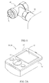
- a heating valve temperature control device of the present invention is applied in a heating valve 40 shown in FIG. 1 , and the valve is installed on a water pipe 42 of a hot-water heating radiator.
- a valve switch lever 41 moves inwards, a water flow in the water pipe gradually decreases till the valve is closed, and when the switch lever 41 moves outwards, the water flow gradually increases till the valve is fully opened, thereby adjusting indoor temperature through the adjustment of the water flow in the water pipe.
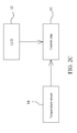
- a heating valve temperature control device of the present invention includes a temperature control unit 10, a motor drive unit 20, and a heating valve drive unit 30.
- the temperature control unit 10 is for controlling and adjusting the indoor temperature, and includes a setting knob or button 11, an LCD 12, a control chip 13, a temperature sensor 14 for detecting the indoor temperature, batteries, and a first casing 15, in which the setting knob or button 11 is for setting the indoor temperature to a suitable temperature, the set temperature is displayed on the LCD 12, and the temperature sensor 14 is for detecting the indoor temperature and sending the detected indoor temperature data to the control chip 13.
- the setting knob or button 11 and the LCD 12 are disposed on a panel of the first casing 15 and are connected to the control chip 13 in the first casing, and the temperature sensor 14 and the batteries (not shown) are installed inside the first casing and are connected to the control chip 13.
- the setting knob or button 11, the LCD 12, the temperature sensor 14 and the control chip 13 may all applies common apparatuses.
- the control chip 13 compares the indoor temperature data detected by the temperature sensor 14 with the temperature set by a user, starts the motor drive unit 20 and the heating valve drive unit 30 to operate if the indoor temperature is different from the temperature set by the user, and adjusts an opening degree of the heating valve 40. The adjustment of the heating valve results in water flow change in the hot water pipe, so that the indoor temperature changes.
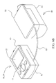
- the first casing 15 has a plugging structure as shown in FIG. 2 and FIG. 6A .
- a first L-shaped step surface 151 is disposed on an lower side of one end of the first casing 15 of the temperature control unit 10, a positioning notch (not shown) is disposed on a center of a vertical surface of the first L-shaped step surface and corresponds to a positioning protrusion 3521 on a second casing 35 of the heating valve control unit in position, and the temperature control unit 10 is powered by a dry cell in the first casing 15.
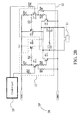
- the motor drive unit 20 includes a cut-off circuit 21 including triodes Q5, Q9 and Q10 and resistors R19-R23, and a conduction circuit 22 including the triodes Q6-Q8 and the resistors R25-R28, in which, an input end of the cut-off circuit 21 is connected to the temperature control unit 10 through the triode Q9 and the resistor R19, and an output end of the cut-off circuit 21 is connected to a DC motor 31 through the triode Q10, the resistor R16 and a capacitor C12.
- An input end of the conduction circuit 22 is connected to the temperature control unit 10 through the triode Q7, and an output end of the conduction circuit 22 is connected to the DC motor 31 through the triode Q8, the resistor R16 and the capacitor C12.
- the motor drive unit 20 is for receiving a control signal of the temperature control unit 10, and driving the DC motor to rotate clockwise or counterclockwise by alternating electrical polarity for supplying a DC current to the DC motor.
- the rotational speed and the number of rotations of the motor are controlled by controlling a time and an interval of power supplied to the DC motor, so as to control the opening degree of the heating valve.
- the triodes Q5 and Q10 are cut off, while the triodes Q6 and Q8 are conducted, and when the motor 311 rotates counterclockwise, the triodes Q6 and Q8 are cut off, while the triodes Q5 and Q10 are conducted, so that the electrical polarity at two ends of the motor is changed.
- the rotational speed and the number of rotations of the motor in a clockwise or counterclockwise direction are determined by the control signal of the temperature control unit, and the rotational speed and the number of rotations of the motor are detected by a Hall sensor 313 of the heating valve drive unit 30.
- the motor drive unit 20 may be selectively connected to the temperature control unit 10 through a wired or wireless manner, and as shown in FIG. 6A , the motor drive unit 20 is disposed inside the first casing 15 of the temperature control unit 10, and the cut-off circuit 21 and the conduction circuit 22 thereof are respectively connected to the temperature control unit 10 and the DC motor 311.
- the integrated temperature control unit may be independently disposed in a place far away from the radiator, and is hung on a wall for example.
- the temperature control unit 10, the motor drive unit 20 and the heating valve drive unit 30 are connected to each other through the wired manner.
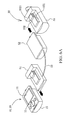
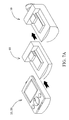
- the temperature control unit 10 and the motor drive unit 20 are plugged to a first junction box 51, and an L-shaped step surface of the first junction box is the same as an L-shaped step surface of the second casing 35 of the heating valve drive unit 30, so that the first junction box 51 may be plugged to the first casing 15 of the temperature control unit 10.
- the heating valve drive unit 30 is plugged to a second junction box 52, and an L-shaped step surface of the second junction box is the same as an L-shaped step surface of the first casing 15 of the temperature control unit 10, so that the second junction box may be plugged to the heating valve drive unit 30.
- the first junction box 51 is connected to the second junction box 52 through a lead 53.
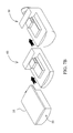
- FIZZ 5A illustrates a wireless connection structure of the motor drive unit and the temperature control unit 10, and in FIG. 5A , a motor drive unit 20B wirelessly connected to the temperature control unit 10 is disposed inside a third casing 24 of the same shape as that of the first casing 15 of the temperature control unit, in which, the third casing 24 may be plugged to the second casing 35 of the heating valve drive unit to form an assembly 30A of the motor drive unit and the heating valve drive unit as shown in FIG.
- a wireless transmitting circuit (not shown) is disposed inside the first casing 15 of the temperature control unit 10, and is connected to the control chip 13 to form a handheld device similar to an air-conditioner remote control, which may be placed in any indoor position.
- the temperature control unit transmits the control signal through the wireless transmitting circuit.
- a wireless receiving circuit (not shown) is disposed inside the motor drive unit 20B, is connected to the cut-off circuit 21 and the conduction circuit 22 of the motor drive unit, and is for receiving the control signal and transferring the signal to the motor drive unit.
- the wireless transmitting circuit is a common high-frequency wireless transmitting circuit
- the wireless receiving circuit is a common high-frequency wireless receiving circuit.
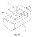
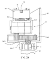
- the heating valve drive unit 30 includes a DC motor 311, a PM 312, a Hall sensor 313, a gearbox 34 and a second casing 35, in which the PM 312 is circular and plate-like, and is installed on an output shaft of the DC motor 311, the Hall sensor 313 is installed outside the PM 312 and is disposed below an installation position of the DC motor in the second casing 35.
- the DC motor 311 rotates
- the PM 312 installed on the output shaft thereof rotates accordingly, and relative to the Hall sensor 313 fixed near the PM, each rotation of the PM brings an N-S pole shift once, and the Hall sensor correspondingly outputs a signal, so that the rotational speed and the number of rotations of the motor are measured.
- the gearbox 34 consists of multiple sets of gears engaged with each other, and in the embodiment as shown in FIG. 3C , the gearbox 34 consists of three sets of gears, in which, an input end gear 341 is connected to the output shaft of the motor 311, and an output end gear 342 may be axially moved. Specifically, an output side of the output end gear 342 is disposed with a screw rod 3421, the screw rod is engaged with an inner nut 343 disposed on an end cover of the gear set, and a tip of a free end of the screw rod 3421 is connected to the switch lever 41 of the heating valve 40.
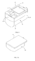
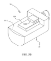
- the DC motor 311, the PM 312, the Hall sensor 313, and the gearbox 34 are disposed inside the second casing 35. As shown in FIG. 3B and FIG.
- a plugging structure corresponding to the first casing is disposed on the second casing 35, and as shown in FIG. 5B and FIG.
- a second L-shaped step surface 351 butted with the L-shaped step surface of the temperature control unit is disposed on a side of the second casing 35 of the heating valve drive unit 30, a positioning block 352 is disposed on the center of the second L-shaped step surface, and a positioning protrusion 3521 corresponding to the positioning notch on the temperature control unit is disposed on the positioning block 352.
- FIG. 4 illustrates an embodiment of an integrated heating valve temperature control device with the motor drive unit 20, the temperature control unit 10 and the heating valve drive unit 30 integrally plugged, in which, the first casing 15 of the temperature control unit 10 and the second casing 35 of the heating valve drive unit 30 are integrally engaged and plugged through the L-shaped step surface 151 of the first casing and the L-shaped step surface 351 of the second casing.
- FIG. 5A illustrates an embodiment of a motor drive unit disposed with the wireless receiving circuit, which has an L-shaped step surface of the third casing 24 same as the L-shaped step surface of the first casing 15 of the temperature control unit, and is disposed with the motor drive unit 20 and the wireless receiving circuit (not shown) therein, and the wireless receiving circuit is a common wireless receiving circuit.
- FIG. 6A illustrates an embodiment of connecting the temperature control unit and the motor drive unit to the heating valve control unit in a wired manner, in which, the temperature control unit 10 and the motor drive unit 20 are connected to the first junction box 51, the first junction box is the same as the second casing 35 of the heating valve drive unit 30 in shape, and is plugged to the first casing 15 of the temperature control unit to form an integrated temperature control unit 10 and motor drive unit 20 as shown in FIG.
- the heating valve control unit 30 is connected to the second junction box 52, and the second junction box is the same as the first casing 15 of the temperature control unit 10 in shape, and is plugged to the second casing 35 of the heating valve control unit to form an integrated heating valve control unit as shown in FIG. 6B , which is connected to the heating valve.
- the first junction box 51 is connected to the second junction box 52 through a lead 53.
- the second junction box 52 is plugged to the second casing 35 of the heating valve control unit to form the integrated heating valve control unit as shown in FIG. 6B , which is connected to the heating valve.
- the first junction box 51 is connected to the second junction box 52 through the lead 53.
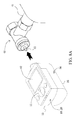
- the L-shaped step surface of the additional battery box 60 or the power adapter connection box 60 of the external power supply is the same as the L-shaped step surface of the second casing 35 of the heating valve drive unit 30, which therefore can be plugged to the first casing 15 of the temperature control unit 10 (as shown in FIG. 7A ) or the motor drive unit 20 disposed with the wireless receiving device (as shown in FIG. 7B ).
- the additional battery box can prolong the service life of the batteries, and the power adapter connection box of the external power supply can be connected to and use the external power supply.
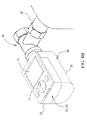
- FIG. 8A and FIG. 8B illustrate a use state of the present invention
- the integrated temperature control unit 10, motor drive unit 20 and heating valve control unit 30 are connected to the switch lever 41 of the heating valve 40 through the gearbox 34 of the heating valve drive unit 30 to form a connection state as shown in FIG. 8B .
- a manually controlled fixing nut is further disposed to fixedly connect the heating valve drive unit to the heating valve.
- the user may pull a hook in the emergence to separate the heating valve drive unit from the heating valve, so as to restore the heat supply.
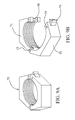
- the manually controlled fixing nut 70 includes two half nuts 71, 72, two turning shafts 73, 74, one manual hook 75, and one rod 76.
- One end of the half screw 71 and one end of the half screw 72 are connected through the turning shaft 73, and the two half screws 71, 72 are capable of rotating about the turning shaft 73 to close or open.
- the other end of the half screw 72 is installed with the turning shaft 74 and the manual hook 75, and the manual hook 75 is capable of rotating about the turning shaft 74.
- the rod 76 is installed on the other end of the half screw 71. After the manual hook 75 hooks the rod 76, the fixing nut 70 is closed and fixedly connects the heating valve drive unit 30 to the heating valve 40.
- the fixing nut 70 is opened, and the heating valve drive unit 30 fixed by the fixing nut is separated from the hating valve 40, so that the heating valve 40 can be opened to supply heat.
Landscapes
- Engineering & Computer Science (AREA)
- General Engineering & Computer Science (AREA)
- Mechanical Engineering (AREA)
- Physics & Mathematics (AREA)
- Thermal Sciences (AREA)
- Chemical & Material Sciences (AREA)
- Combustion & Propulsion (AREA)
- Electrically Driven Valve-Operating Means (AREA)
- Details Of Valves (AREA)
Applications Claiming Priority (1)
| Application Number | Priority Date | Filing Date | Title |
|---|---|---|---|
| PCT/CN2009/070499 WO2010094177A1 (zh) | 2009-02-23 | 2009-02-23 | 暖气阀门温度控制装置 |
Publications (1)
| Publication Number | Publication Date |
|---|---|
| EP2400227A1 true EP2400227A1 (de) | 2011-12-28 |
Family
ID=42633424
Family Applications (1)
| Application Number | Title | Priority Date | Filing Date |
|---|---|---|---|
| EP09840228A Withdrawn EP2400227A1 (de) | 2009-02-23 | 2009-02-23 | Temperaturregelvorrichtung für radiatorventil |
Country Status (2)
| Country | Link |
|---|---|
| EP (1) | EP2400227A1 (de) |
| WO (1) | WO2010094177A1 (de) |
Cited By (7)
| Publication number | Priority date | Publication date | Assignee | Title |
|---|---|---|---|---|
| CN103631287A (zh) * | 2013-11-27 | 2014-03-12 | 南京三创自动化科技有限公司 | 一种用于变速箱的润滑油外循环温度控制装置 |
| WO2016142769A1 (de) * | 2015-03-10 | 2016-09-15 | Zehnder Group International Ag | Temperierkörper |
| IT201600108293A1 (it) * | 2016-10-26 | 2018-04-26 | Caleffi Spa | Dispositivo valvolare miscelatore |
| CN109944953A (zh) * | 2019-03-15 | 2019-06-28 | 汉工阀门股份有限公司 | 一种高压直流式截止阀 |
| EP3619448A1 (de) * | 2017-05-04 | 2020-03-11 | Fisher Controls International Llc | Vorrichtung zum verbinden eines ventilschafts mit einem aktuator |
| EP3276267B1 (de) * | 2016-07-27 | 2021-04-07 | Computime, Ltd. | Automatische ausgleichsventilanordnung, verfahren zum steuern von wasser-durchfluss und ein computerlesbares medium |
| EP4180899B1 (de) * | 2021-11-10 | 2025-04-23 | tado GmbH | Heizkörperthermostat |
Families Citing this family (1)
| Publication number | Priority date | Publication date | Assignee | Title |
|---|---|---|---|---|
| CN102980242A (zh) * | 2012-11-22 | 2013-03-20 | 宁夏赛文节能服务有限公司 | 阀门智能控制系统 |
Family Cites Families (8)
| Publication number | Priority date | Publication date | Assignee | Title |
|---|---|---|---|---|
| AT383660B (de) * | 1984-05-03 | 1987-08-10 | Schrack Elektronik Ag | Regelventil |
| DE3509353C1 (de) * | 1985-03-15 | 1986-06-12 | Polytronic Kunststoff-Elektro Gmbh, 4796 Salzkotten | Regeleinrichtung für ein Thermostatventil |
| GB2216293B (en) * | 1988-03-01 | 1992-02-19 | David Philip Reynolds | Valves |
| DE9005848U1 (de) * | 1990-05-23 | 1990-07-26 | Studentenwerk Freiburg Anstalt des öffentl. Rechts, 7800 Freiburg | Regelgerät |
| US6044857A (en) * | 1997-02-13 | 2000-04-04 | Erie Manufacturing Company | Electronic controller for a modulating valve |
| CN2826235Y (zh) * | 2005-08-01 | 2006-10-11 | 王小宁 | 电磁阀式室内温度控制器 |
| CN201014018Y (zh) * | 2007-03-15 | 2008-01-30 | 金成官 | 温控阀控制装置 |
| CN201071969Y (zh) * | 2007-08-21 | 2008-06-11 | 孙振宇 | 散热器调节阀开度设定的控制装置 |
-
2009
- 2009-02-23 EP EP09840228A patent/EP2400227A1/de not_active Withdrawn
- 2009-02-23 WO PCT/CN2009/070499 patent/WO2010094177A1/zh not_active Ceased
Non-Patent Citations (1)
| Title |
|---|
| See references of WO2010094177A1 * |
Cited By (10)
| Publication number | Priority date | Publication date | Assignee | Title |
|---|---|---|---|---|
| CN103631287A (zh) * | 2013-11-27 | 2014-03-12 | 南京三创自动化科技有限公司 | 一种用于变速箱的润滑油外循环温度控制装置 |
| WO2016142769A1 (de) * | 2015-03-10 | 2016-09-15 | Zehnder Group International Ag | Temperierkörper |
| EP3276267B1 (de) * | 2016-07-27 | 2021-04-07 | Computime, Ltd. | Automatische ausgleichsventilanordnung, verfahren zum steuern von wasser-durchfluss und ein computerlesbares medium |
| IT201600108293A1 (it) * | 2016-10-26 | 2018-04-26 | Caleffi Spa | Dispositivo valvolare miscelatore |
| WO2018077807A1 (en) * | 2016-10-26 | 2018-05-03 | Caleffi S.P.A. | Mixer valve device |
| US11448328B2 (en) | 2016-10-26 | 2022-09-20 | Caleffi S.P.A. | Mixer valve device |
| EP3619448A1 (de) * | 2017-05-04 | 2020-03-11 | Fisher Controls International Llc | Vorrichtung zum verbinden eines ventilschafts mit einem aktuator |
| CN109944953A (zh) * | 2019-03-15 | 2019-06-28 | 汉工阀门股份有限公司 | 一种高压直流式截止阀 |
| CN109944953B (zh) * | 2019-03-15 | 2020-03-31 | 汉工阀门股份有限公司 | 一种高压直流式截止阀 |
| EP4180899B1 (de) * | 2021-11-10 | 2025-04-23 | tado GmbH | Heizkörperthermostat |
Also Published As
| Publication number | Publication date |
|---|---|
| WO2010094177A1 (zh) | 2010-08-26 |
Similar Documents
| Publication | Publication Date | Title |
|---|---|---|
| US20150354848A1 (en) | Device for Influencing the room climate | |
| WO2010094177A1 (zh) | 暖气阀门温度控制装置 | |
| CN109027378B (zh) | 触摸式恒温水龙头系统 | |
| CN201401869Y (zh) | 暖气阀门温度控制装置 | |
| US20210388584A1 (en) | Electronic shower valve | |
| WO2008008781A2 (en) | Vacuum control system for a breast pump | |
| US20090095106A1 (en) | Motorized gear and coupling system | |
| US20090111373A1 (en) | Motorized gear and coupling system | |
| CN108954492B (zh) | 一种智能浴霸开关及浴霸控制方法 | |
| EP0923013A1 (de) | Thermostatventilkopf | |
| CN212775687U (zh) | 智能阀门 | |
| CN205841920U (zh) | 一种触摸式恒温水龙头系统 | |
| GB2472084A (en) | Radiator control apparatus | |
| ITMI20120085A1 (it) | Dispositivo di comando temporizzato di un fuoco di un piano cottura | |
| CN205592479U (zh) | 一种自动恒温控制器 | |
| CN211449817U (zh) | 一种调节型电动执行器 | |
| CN102667279B (zh) | 用于有壳体的或无壳体的配件的操纵装置 | |
| CN203430820U (zh) | 一种自动定位风向的风扇 | |
| CN201844588U (zh) | 太阳能热水器电动恒温器 | |
| CN205610430U (zh) | 一种新型自动调节散热的振动电机 | |
| KR101545200B1 (ko) | 에어컨 실외기용 루버 시스템 및 그 제어방법 | |
| CN100526779C (zh) | 双腔体电加热炉 | |
| CN209370524U (zh) | 一种公共建筑采暖自动节能阀 | |
| KR20120003893U (ko) | 제베크 열전소자를 이용한 디퓨저의 통풍 자동 개폐기 | |
| JP3637831B2 (ja) | 空気調和機の制御装置 |
Legal Events
| Date | Code | Title | Description |
|---|---|---|---|
| PUAI | Public reference made under article 153(3) epc to a published international application that has entered the european phase |
Free format text: ORIGINAL CODE: 0009012 |
|
| 17P | Request for examination filed |
Effective date: 20110720 |
|
| AK | Designated contracting states |
Kind code of ref document: A1 Designated state(s): AT BE BG CH CY CZ DE DK EE ES FI FR GB GR HR HU IE IS IT LI LT LU LV MC MK MT NL NO PL PT RO SE SI SK TR |
|
| DAX | Request for extension of the european patent (deleted) | ||
| STAA | Information on the status of an ep patent application or granted ep patent |
Free format text: STATUS: THE APPLICATION IS DEEMED TO BE WITHDRAWN |
|
| 18D | Application deemed to be withdrawn |
Effective date: 20140902 |