EP2400293A1 - Messgerät für den Salzgehalt - Google Patents
Messgerät für den Salzgehalt Download PDFInfo
- Publication number
- EP2400293A1 EP2400293A1 EP11170847A EP11170847A EP2400293A1 EP 2400293 A1 EP2400293 A1 EP 2400293A1 EP 11170847 A EP11170847 A EP 11170847A EP 11170847 A EP11170847 A EP 11170847A EP 2400293 A1 EP2400293 A1 EP 2400293A1
- Authority
- EP
- European Patent Office
- Prior art keywords
- salinity
- capacitor
- voltage
- unit
- measuring apparatus
- Prior art date
- Legal status (The legal status is an assumption and is not a legal conclusion. Google has not performed a legal analysis and makes no representation as to the accuracy of the status listed.)
- Withdrawn
Links
Images




Classifications
-
- G—PHYSICS
- G01—MEASURING; TESTING
- G01N—INVESTIGATING OR ANALYSING MATERIALS BY DETERMINING THEIR CHEMICAL OR PHYSICAL PROPERTIES
- G01N27/00—Investigating or analysing materials by the use of electric, electrochemical, or magnetic means
- G01N27/02—Investigating or analysing materials by the use of electric, electrochemical, or magnetic means by investigating impedance
- G01N27/028—Circuits therefor
-
- G—PHYSICS
- G01—MEASURING; TESTING
- G01N—INVESTIGATING OR ANALYSING MATERIALS BY DETERMINING THEIR CHEMICAL OR PHYSICAL PROPERTIES
- G01N27/00—Investigating or analysing materials by the use of electric, electrochemical, or magnetic means
- G01N27/02—Investigating or analysing materials by the use of electric, electrochemical, or magnetic means by investigating impedance
- G01N27/04—Investigating or analysing materials by the use of electric, electrochemical, or magnetic means by investigating impedance by investigating resistance
- G01N27/06—Investigating or analysing materials by the use of electric, electrochemical, or magnetic means by investigating impedance by investigating resistance of a liquid
-
- G—PHYSICS
- G01—MEASURING; TESTING
- G01N—INVESTIGATING OR ANALYSING MATERIALS BY DETERMINING THEIR CHEMICAL OR PHYSICAL PROPERTIES
- G01N27/00—Investigating or analysing materials by the use of electric, electrochemical, or magnetic means
- G01N27/02—Investigating or analysing materials by the use of electric, electrochemical, or magnetic means by investigating impedance
- G01N27/22—Investigating or analysing materials by the use of electric, electrochemical, or magnetic means by investigating impedance by investigating capacitance
- G01N27/223—Investigating or analysing materials by the use of electric, electrochemical, or magnetic means by investigating impedance by investigating capacitance for determining moisture content, e.g. humidity
-
- G—PHYSICS
- G01—MEASURING; TESTING
- G01N—INVESTIGATING OR ANALYSING MATERIALS BY DETERMINING THEIR CHEMICAL OR PHYSICAL PROPERTIES
- G01N33/00—Investigating or analysing materials by specific methods not covered by groups G01N1/00 - G01N31/00
- G01N33/02—Food
-
- G—PHYSICS
- G01—MEASURING; TESTING
- G01N—INVESTIGATING OR ANALYSING MATERIALS BY DETERMINING THEIR CHEMICAL OR PHYSICAL PROPERTIES
- G01N33/00—Investigating or analysing materials by specific methods not covered by groups G01N1/00 - G01N31/00
- G01N33/26—Oils; Viscous liquids; Paints; Inks
- G01N33/28—Oils, i.e. hydrocarbon liquids
- G01N33/2835—Specific substances contained in the oils or fuels
- G01N33/2852—Alcohol in fuels
-
- G—PHYSICS
- G01—MEASURING; TESTING
- G01R—MEASURING ELECTRIC VARIABLES; MEASURING MAGNETIC VARIABLES
- G01R27/00—Arrangements for measuring resistance, reactance, impedance, or electric characteristics derived therefrom
- G01R27/02—Measuring real or complex resistance, reactance, impedance, or other two-pole characteristics derived therefrom, e.g. time constant
-
- G—PHYSICS
- G01—MEASURING; TESTING
- G01R—MEASURING ELECTRIC VARIABLES; MEASURING MAGNETIC VARIABLES
- G01R27/00—Arrangements for measuring resistance, reactance, impedance, or electric characteristics derived therefrom
- G01R27/02—Measuring real or complex resistance, reactance, impedance, or other two-pole characteristics derived therefrom, e.g. time constant
- G01R27/22—Measuring resistance of fluids
-
- G—PHYSICS
- G01—MEASURING; TESTING
- G01N—INVESTIGATING OR ANALYSING MATERIALS BY DETERMINING THEIR CHEMICAL OR PHYSICAL PROPERTIES
- G01N27/00—Investigating or analysing materials by the use of electric, electrochemical, or magnetic means
- G01N27/02—Investigating or analysing materials by the use of electric, electrochemical, or magnetic means by investigating impedance
- G01N27/22—Investigating or analysing materials by the use of electric, electrochemical, or magnetic means by investigating impedance by investigating capacitance
- G01N27/221—Investigating or analysing materials by the use of electric, electrochemical, or magnetic means by investigating impedance by investigating capacitance by investigating the dielectric properties
Definitions
- Embodiments relate to a salinity measuring apparatus to measure salinity of a solution.
- Kimchi is a traditional Korean food produced through fermentation.
- the rate of fermentation of Kimchi varies according to temperature and salinity.
- the rate of fermentation of Kimchi is increased if temperature is high and salinity is low and is decreased if temperature is low and salinity is high.
- the internal temperature of a Kimchi storage chamber and salinity of Kimchi need to be measured.
- the existing salinity measuring apparatus includes a salinity sensing unit having a pair of measuring electrodes and a capacitor, and a switching unit operating according to an output signal of the salinity sensing unit so as to switch a voltage supplied to the salinity sensing unit.
- a salinity measuring apparatus converts the voltage of the capacitor changed according to salinity into a frequency using predetermined upper and lower limit values and measures salinity according to the frequency.
- the existing salinity measuring apparatus when salinity is consecutively measured, a DC voltage component is partially supplied to the measuring electrodes, such that, over time, ions are accumulated in the measuring electrodes. Thus, electrical conductivity is lowered with over time. Accordingly, even when food having the same salinity is measured, since electrical conductivity is lowered due to ions accumulated in the measuring electrodes, the measured salinity may be changed whenever the salinity is measured. In addition, salinity lower than actual salinity may be measured and thus reliability of measured data may be reduced.
- a salinity measuring apparatus to determine salinity of food, the salinity measuring apparatus including: a salinity sensing unit including a pair of measuring electrodes and a capacitor; a switching unit to switch a voltage of the capacitor of the salinity sensing unit; and a control unit to provide a pulse signal with a constant frequency to the switching unit and to determine the salinity of the food which is in contact with the measuring electrodes of the salinity sensing unit based on when the voltage of the capacitor reaches a reference voltage.
- the capacitor may be connected to any one of the measuring electrodes in series.
- the salinity sensing unit may further include a resistor connected between the measuring electrodes in parallel.
- the salinity measuring apparatus may further include a memory unit to store a salinity value varying according to when the voltage of the capacitor reaches the reference voltage.
- the salinity measuring apparatus may further include a comparison unit to compare the voltage of the capacitor of the salinity sensing unit with the reference voltage and to output a high-level signal or a low-level signal according to the comparison result, and the control unit may determine when the voltage of the capacitor reaches the reference voltage based on a variation in output signal of the comparison unit.
- the salinity measuring apparatus may further include an AD converter connected to the capacitor so as to convert an analog voltage signal of the capacitor into a digital signal, and the time when the voltage of the capacitor reaches the reference voltage may be determined according to the digital signal converted by the AD converter.
- the control unit may control the switching unit such that the capacitor is discharged when the voltage of the capacitor reaches the reference voltage.
- the period of the pulse signal may include a period when the voltage of the capacitor is substantially 0.
- the salinity measuring apparatus may further include a discharging unit connected to one side of the capacitor of the salinity sensing unit so as to discharge the capacitor.
- the operation of the discharging unit may interlock with a discharging operation of the switching unit.
- a salinity measuring apparatus including: a salinity sensing unit including a pair of measuring electrodes and a capacitor; a switching unit to switch a voltage of the capacitor of the salinity sensing unit; and a control unit to provide a pulse signal with a constant frequency to the switching unit, to determine a duty ratio of the pulse signal when the voltage of the capacitor reaches the reference voltage, and to determine salinity of food which is in contact with the measuring electrodes of the salinity sensing unit according to the determined duty ratio.
- the salinity measuring apparatus may further include a memory unit to store a salinity value corresponding to the duty ratio.
- the salinity measuring apparatus may further include a comparison unit to compare the voltage of the capacitor of the salinity sensing unit with the reference voltage and to output a high-level signal or a low-level signal according to the comparison result, and the control unit may determine a time from when the pulse signal is output to the switching unit to when the output signal of the comparison unit is changed, as the duty ratio of the pulse signal.
- the control unit may control the switching unit such that the capacitor is discharged when the voltage of the capacitor reaches the reference voltage.
- the period of the pulse signal may include a period when the voltage of the capacitor is substantially 0.
- the salinity measuring apparatus may further include a discharging unit connected to one side of the capacitor of the salinity sensing unit so as to discharge the capacitor.
- the operation of the discharging unit may interlock with a discharging operation of the switching unit.
- a salinity measuring apparatus including: a salinity sensing unit including a pair of measuring electrodes and a capacitor; a switching unit switched to charge or discharge the capacitor of the salinity sensing unit; and a control unit to control the switching unit so as to charge the capacitor and to control the switching unit so as to discharge the capacitor when the voltage of the capacitor reaches a reference voltage.
- the salinity measuring apparatus may further include a comparison unit to compare the voltage of the capacitor of the salinity sensing unit with the reference voltage and to output a high-level signal or a low-level signal according to the comparison result, and the control unit may determine whether or not the voltage of the capacitor reaches the reference voltage based on variation in an output signal of the comparison unit.
- the period of the pulse signal may include a period when the voltage of the capacitor is substantially 0.
- a salinity measuring apparatus including: a salinity sensing unit including a pair of measuring electrodes and a capacitor; a switching unit to switch a voltage applied to the salinity sensing unit; and a control unit to provide a pulse signal with a constant frequency to the switching unit, to change a duty ratio of the pulse signal based on when the voltage of the capacitor reaches a reference voltage, and to determine salinity of food which is in contact with the measuring electrodes of the salinity sensing unit.
- the pulse signal with the constant frequency to the switching unit it is possible to minimize the internal impedance variation of the capacitor and to more accurately measure the salinity of the food.
- the frequency of the pulse signal provided to the switching unit is only constant, it is possible to reduce the frequency of the pulse signal, to reduce the switching loss of the switching unit, and to reduce energy consumption.
- FIG. 1 is a perspective view of a Kimchi refrigerator to which a salinity measuring apparatus according to an embodiment is applied.
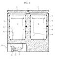
- FIG. 2 is a cross-sectional view taken along line II-II of the Kimchi refrigerator shown in FIG. 1 .
- the Kimchi refrigerator to which the salinity measuring apparatus according to the embodiment of the present invention is applied, includes a main body 10.
- a function selection unit 25 is provided on an upper side of a front surface of the main body 10.
- a first storage chamber 12 and a second storage chamber 13 are formed in the main body 10.
- Doors 11 to open or close the first storage chamber 12 and the second storage chamber 13 are hinge-coupled to an upper side of the main body 10.
- the first storage chamber 12 and the second storage chamber 13 are separated by a partition.
- An insulator to maintain the temperatures of the first storage chamber 12 and the second storage chamber 13 is filled between outer surfaces of the first storage chamber 12 and the second storage chamber 13.
- a first evaporator 14 to perform a heat exchange operation and a first temperature sensor 16 to detect a surface temperature of the first evaporator 14 in order to sense the temperature of the first storage chamber 12 are provided on the outer circumference of the first storage chamber 12.
- a second evaporator 15 to perform a heat exchange operation and a second temperature sensor 17 to detect a surface temperature of the second evaporator 15 in order to sense the temperature of the second storage chamber 13 are provided on the outer circumference of the second storage chamber 13.
- a machine room 20 including cooling devices is provided below the first storage chamber 12 and the second storage chamber 13.
- a compressor 21 to compress refrigerant, a condenser to condense the refrigerant compressed by the compressor 21, and a fan 23 provided on one side of the condenser 22 to force air to the condenser 22 are provided.
- a storage container 30 to store Kimchi is received in each of the first storage chamber 12 and the second storage chamber 13.
- a salinity measuring apparatus 40 to measure the salinity of food stored in the storage container, such as Kimchi is mounted in the storage container 30.
- the salinity measuring apparatus 40 is provided inside the storage container 30 such that measuring electrodes are in contact with the liquid of the food stored in the storage container 30, thereby measuring salinity.
- the salinity measuring apparatus 40 has a pair of measuring electrodes spaced apart from each other with a predetermined gap therebetween.
- the measuring electrodes are provided so as to be in contact with the liquid of the food stored in the storage chamber.
- the salinity measuring apparatus 40 applies a voltage to the pair of measuring electrodes so as to measure electrical conductivity between the measuring electrodes and to measure the salinity of the food based on the electric conductivity.
- the electric conductivity is increased, the salinity of Kimchi is increased and as the electric conductivity is decreased, the salinity of Kimchi is decreased.
- the Kimchi refrigerator having the above-described configuration sets a fermentation time or a fermentation temperature according to a fermentation mode or a ripening step determined by user selection according to the salinity of the food measured by the salinity measuring apparatus 40.
- an appropriate fermentation period can be determined according to the salinity of Kimchi such that the food is fermented to a desired degree regardless of the salinity of the food.
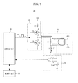
- FIG. 3 is a block diagram of a salinity measuring apparatus according to an embodiment.
- the salinity measuring apparatus 40 includes a salinity sensing unit 41, a switching unit 42, a comparison unit 43, a memory unit 44, and a control unit 45 to perform overall control.
- the salinity sensing unit 41 includes a pair of measuring electrodes 41a and 41b, a resistor R1 and a capacitor C 1.
- the pair of measuring electrodes 41 a and 41 b includes the first electrode 41 a and the second electrode 41 b spaced apart from the first electrode 41 with a predetermined gap therebetween so as not to be in contact with the first electrode 41 a.
- the first electrode 41 a and the second electrode 41 b are provided so as to be in contact with the liquid of the food stored in the storage chamber.
- the capacitor C1 is connected to the second electrode 41 b of the pair of measuring electrodes in series.
- the first electrode 41 a and the second electrode 41 b are connected to both ends of the resistor R1. That is, the resistor R1 is connected between the first electrode 41 a and the second electrode 41 b in parallel.
- the switching unit 42 supplies voltage to the salinity sensing unit 41 according to a pulse signal (e.g., a Pulse Width Modulation (PWM) signal) with a constant frequency, which is output from the control unit 45, so as to charge the capacitor C1 or to discharge the capacitor C1 to a ground side.
- a pulse signal e.g., a Pulse Width Modulation (PWM) signal
- PWM Pulse Width Modulation
- the switching unit 42 includes two transistors Q1 and Q2.
- the two transistors Q1 and Q2 include the first switching element Q1 which is a PNP transistor and a second switching element Q2 which is an NPN transistor.
- the base B of the first switching element Q1 and the base B of the second switching element Q2 are connected to each other.
- the emitter E of the first switching element Q1 is connected to a source voltage Vcc.
- the collector C of the second switching element Q2 is connected to the collector C of the first switching element Q1.
- the emitter E of the second switching element Q2 is grounded.
- the resistor R1 and the capacitor C1 are connected in series between the collectors C of the first and second switching elements Q1 and Q2 and the ground.
- the comparison unit 43 compares the voltage of the capacitor C1 of the salinity sensing unit 41 with a predetermined reference voltage Vref and outputs a high-level signal or a low-level signal to the control unit 45 according to the comparison result.
- the control unit switches the first switching element Q1 of the switching unit 42 off upon sensing that a signal has changed from a high level to a low level.
- the comparison unit 43 includes a comparator having a non-inverting input terminal (+) and an inverting input terminal (-).
- the inverting input terminal (-) of the comparison unit 43 is connected to a connection node between the second electrode 41 b and the capacitor C1.
- the reference voltage Vref is input to the non-inverting input terminal (+) of the comparison unit 43
- the comparison unit 43 outputs a low-level signal when the voltage value input to the inverting input terminal (-) is higher than the reference voltage value Vref input to the non-inverting input terminal (+). In addition, the comparison unit 43 outputs a high-level signal when the voltage value input to the inverting input terminal (-) is lower than the reference voltage value Vref input to the non-inverting input terminal (+).
- the control unit 45 includes a microcomputer.
- the control unit 45 outputs the pulse signal (e.g., the PWM signal) with the constant frequency to the switching unit 42 such that an AC voltage is supplied to the salinity sensing unit 41, and switches the first switching element Q1 of the switching unit 42 on so as to charge the capacitor C1 of the salinity sensing unit 41. At this time, the second switching element Q2 is switched off.
- the pulse signal e.g., the PWM signal
- the control unit 45 controls the duty ratio of the PWM signal output to the switching unit 42 such that the capacitor C1 of the salinity sensing unit 41 is discharged, if the signal received from the comparison unit 43 is changed from the high-level signal to the low-level signal.
- the first switching element Q1 of the switching unit 42 is switched off and the second switching element Q2 is switched on such that the capacitor C1 is discharged to the ground side through the second switching element Q2.
- control unit 45 determines the salinity of the food which is in contact with the measuring electrodes 41a and 41b of the salinity sensing unit 41 based on a time when the voltage of the capacitor C1 reaches the reference voltage.
- Salinity-time data is stored in the memory unit 44.
- the time value changed according to the salinity of the standard food measured by experiments is stored in the memory unit 44.
- the control unit 45 may determine the salinity of the food by checking the duty ratio of the PWM signal. In this case, salinity-duty ratio data is stored in the memory unit 44.
- FIG. 4 is a diagram showing a state in which a voltage is applied to a capacitor through the measuring electrodes of the salinity sensing unit shown in FIG. 3 so as to charge the capacitor.
- FIG. 5 is a timing chart illustrating a variation in time when the voltage of the capacitor reaches a reference voltage according to a salinity variation and a variation in duty ratio of a Pulse Width Modulation (PWM) signal, in the salinity measuring apparatus according to the embodiment.
- PWM Pulse Width Modulation
- FIG. 6 is a diagram showing a state in which the capacitor is discharged through the measuring electrodes of the salinity sensing unit shown in FIG. 3 .
- FIG. 7 is a timing chart illustrating the voltage of the capacitor according to an operation of a switching unit in the salinity measuring apparatus according to the embodiment.
- the control unit 45 switches the first switching element Q1 of the switching unit 42 on and switches the second switching element Q2 off during an on time period (see a solid line of the PWM signal) of the PWM signal output to the switching unit 42 (see FIG. 7 ). Accordingly, current flows in an arrow direction so as to charge the capacitor C1.
- the charging time of the capacitor C1 is changed according to salinity.
- the time when the voltage of the capacitor C1 reaches the reference voltage Vref is changed according to salinity. That is, when salinity is high, the time when the voltage A (solid arrow) of the capacitor C1 reaches the reference voltage Vref is "t1". In contrast, when salinity is low, since the conductivity between the measuring electrodes 41 a and 41 b is relatively low, the time when the voltage B (dotted arrow) of the capacitor C1 reaches the reference voltage Vref is "t2" greater than "t1".
- the time when the voltage of the capacitor C1 reaches the reference voltage is changed according to a salinity variation. That is, as the salinity is increased, the time when the voltage A of the capacitor C1 reaches the reference voltage Vref is decreased (t1 ⁇ t2).
- the control unit 45 switches the first switching element Q1 of the switching unit 42 off and switches the second switching element Q2 on during an off time period (see a solid line of the PWM signal) of the PWM signal output to the switching unit 42 (see FIG. 7 ). Accordingly, current flows in an arrow direction so as to discharge the capacitor C1.
- FIG. 8 is a diagram illustrating the existence of a period when the voltage of the capacitor is substantially 0 when the capacitor is discharged, in the salinity measuring apparatus according to the embodiment.
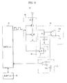
- FIG. 9 is a block diagram of a salinity measuring apparatus according to another embodiment.
- the salinity measuring apparatus may include a discharging unit 46 to effectively discharge the capacitor C1 of the salinity sensing unit 41.
- the discharging unit 46 is provided between the salinity sensing unit 41 and the switching unit 42.
- the discharging unit 46 includes a freewheeling diode D3 and a third switching element Q3.
- the collector C of the third switching element Q3 is connected to one side of the capacitor C1 of the salinity sensing unit 41 and the emitter thereof is connected to the ground side.
- the bases B of the third switching element Q3 and the second switching element Q2 are connected to each other such that the operation of the third switching element Q3 interlocks with the operation of the second switching element Q2.
- the periods tb-ta and tc-tb when the voltage of the capacitor is substantially 0 may be increased and more easily secured.
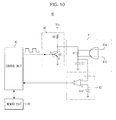
- FIG. 10 is a block diagram of a salinity measuring apparatus according to another embodiment.
- one switching element is used instead of the two switching elements in the switching unit 42 of the salinity measuring apparatus shown in FIG. 3 .
- the salinity measuring apparatus includes a salinity sensing unit 41, a switching unit 42 including one switching element Q1, a comparison unit 43, a memory unit 44 and a control unit 45 to perform overall control.
- the salinity sensing unit 41 includes a first electrode 41 a and a second electrode 41 b spaced apart from the first electrode 41 a with a predetermined gap therebetween so as not to be in contact with the first electrode 41 a, and includes the pair of measuring electrodes 41 a and 41 b provided to be in contact with the liquid of the food stored in the storage chamber, the resistor R1 and the capacitor C1 connected to the second electrode 41 b of the measuring electrodes 41 a and 41 b in series.
- the switching unit 42 supplies a voltage to the salinity sensing unit 41 according to a PWM signal with a constant frequency, which is output from the control unit 45, so as to charge the capacitor C1 or to discharge the capacitor C1 to a ground side.
- the switching unit 42 includes one transistor Q1.
- the transistor is an NPN transistor Q1.
- the switching element Q1 If the switching element Q1 is switched off, the voltage is supplied to the salinity sensing unit 41 so as to charge the capacitor C1. In contrast, if the switching element Q1 is switched on, the capacitor C1 of the salinity sensing unit 41 is discharged.
- the comparison unit 43 compares the voltage of the capacitor C1 of the salinity sensing unit 41 with a predetermined reference voltage Vref and outputs a high-level signal or a low-level signal to the control unit 45 according to the comparison result. For example, the comparison unit 43 outputs a high-level signal if the input voltage value is less than the reference voltage Vref and outputs a low-level signal if the input voltage value is higher than the reference voltage Vref.
- the control unit 45 outputs the pulse signal (PWM signal) with the constant frequency to the switching unit 42 such that an AC voltage is supplied to the salinity sensing unit 41 and switches the switching element Q1 of the switching unit 42 off. Then, the capacitor C1 of the salinity sensing unit 41 is charged.
- control unit 45 controls the PWM signal output to the switching unit 42 such that the capacitor C1 of the salinity sensing unit 41 is discharged and switches the switching element Q1 of the switching unit 41 on. Then, the capacitor C1 of the salinity sensing unit 41 is discharged.
- control unit 45 determines the salinity of the food which is in contact with the measuring electrodes 41a and 41b of the salinity sensing unit 41 based on when the voltage of the capacitor C1 reaches the reference voltage.
- Salinity-time data is stored in the memory unit 44.
- the time values changed according to the salinity of the standard food measured by experiments are stored in the memory unit 44.
- the control unit 45 may determine the salinity of the food by checking the duty ratio of the PWM signal. In this case, salinity-duty ratio data is stored in the memory unit 44.
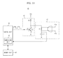
- FIG. 11 is a block diagram of a salinity measuring apparatus according to another embodiment.
- the function of the comparison unit 43 of the salinity measuring apparatus shown in FIG. 9 is incorporated into the control unit 45.
- the salinity measuring apparatus includes a salinity sensing unit 41, a switching unit 42 including one switching element Q1, a memory unit 44 and a control unit 45 including a comparison unit 43.
- the salinity sensing unit 41 includes a first electrode 41 a and a second electrode 41 b spaced apart from the first electrode 41 a with a predetermined gap therebetween so as not to be in contact with the first electrode 41 a, and includes the pair of measuring electrodes 41 a and 41 b provided to be in contact with the liquid of the food stored in the storage chamber, the resistor R1 and the capacitor C1 connected to the second electrode 41 b of the measuring electrodes 41 a and 41 b in series.
- the switching unit 42 supplies a voltage to the salinity sensing unit 41 according to a PWM signal with a constant frequency, which is output from the control unit 45, so as to charge the capacitor C1 or to discharge the capacitor C1 to a ground side.
- the switching unit 42 includes one transistor Q1.
- the transistor is an NPN transistor Q1.
- the switching element Q1 If the switching element Q1 is switched off, the voltage is supplied to the salinity sensing unit 41 so as to charge the capacitor C1. In contrast, if the switching element Q1 is switched on, the capacitor C1 of the salinity sensing unit 41 is discharged.
- the control unit 45 outputs the pulse signal (e.g., PWM signal) with the constant frequency to the switching unit 42 such that an AC voltage is supplied to the salinity sensing unit 41 and switches the switching element Q1 of the switching unit 42 off. Then, the capacitor C1 of the salinity sensing unit 41 is charged.
- PWM signal pulse signal
- control unit 45 determines whether the voltage of the capacitor C1 of the salinity sensing unit 41 is higher or lower than the reference voltage Vref, from the output signal of the comparison unit 43. At this time, when the output signal of the comparison unit 43 is changed from the high-level signal to the low-level signal, the control unit 45 determines that the voltage of the capacitor C1 reaches the reference voltage Vref.
- control unit 45 determines the salinity of the food which is in contact with the measuring electrodes 41 a and 41 b of the salinity sensing unit 41 based on a time when the voltage of the capacitor C1 reaches the reference voltage.
- the control unit 45 may determine the salinity of the food by checking the duty ratio of the PWM signal. In this case, salinity-duty ratio data is stored in the memory unit 44.
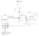
- FIG. 12 is a block diagram of a salinity measuring apparatus according to another embodiment.
- control unit 45 includes an AD converter 47 to convert an analog signal into a digital signal, instead of the comparison unit 43.
- the salinity measuring apparatus includes a salinity sensing unit 41, a switching unit 42, a memory unit 44, an AD converter 47, and a control unit 45 to perform overall control.
- the control unit 45 may include the AD converter 47.
- the AD converter 47 is connected to the capacitor C1 of the salinity sensing unit 41 so as to convert the analog voltage signal of the capacitor C1 into a digital signal and to output the digital signal to the control unit 45.
- the control unit 45 recognizes the voltage of the capacitor C1 from the digital signal input through the AD converter 47 and counts the time when the recognized capacitor voltage reaches the reference voltage Vref so as to determine the time when the voltage of the capacitor reaches the reference voltage Vref.
- control unit 45 determines the salinity of the food which is in contact with the measuring electrodes 41 a and 41 b of the salinity sensing unit 41 based on the time when the voltage of the capacitor C1 reaches the reference voltage.
- the control unit 45 may determine the salinity of the food by checking the duty ratio of the PWM signal. In this case, salinity-duty ratio data is stored in the memory unit 44.
Landscapes
- Chemical & Material Sciences (AREA)
- General Physics & Mathematics (AREA)
- Physics & Mathematics (AREA)
- Life Sciences & Earth Sciences (AREA)
- Health & Medical Sciences (AREA)
- General Health & Medical Sciences (AREA)
- Analytical Chemistry (AREA)
- Biochemistry (AREA)
- Immunology (AREA)
- Pathology (AREA)
- Engineering & Computer Science (AREA)
- Food Science & Technology (AREA)
- Chemical Kinetics & Catalysis (AREA)
- Electrochemistry (AREA)
- Medicinal Chemistry (AREA)
- Investigating Or Analyzing Materials By The Use Of Electric Means (AREA)
- General Chemical & Material Sciences (AREA)
- Oil, Petroleum & Natural Gas (AREA)
Applications Claiming Priority (1)
| Application Number | Priority Date | Filing Date | Title |
|---|---|---|---|
| KR1020100059910A KR101741083B1 (ko) | 2010-06-24 | 2010-06-24 | 염도 측정 장치 |
Publications (1)
| Publication Number | Publication Date |
|---|---|
| EP2400293A1 true EP2400293A1 (de) | 2011-12-28 |
Family
ID=44561248
Family Applications (1)
| Application Number | Title | Priority Date | Filing Date |
|---|---|---|---|
| EP11170847A Withdrawn EP2400293A1 (de) | 2010-06-24 | 2011-06-22 | Messgerät für den Salzgehalt |
Country Status (4)
| Country | Link |
|---|---|
| US (1) | US8963564B2 (de) |
| EP (1) | EP2400293A1 (de) |
| KR (1) | KR101741083B1 (de) |
| CN (1) | CN102368058A (de) |
Cited By (2)
| Publication number | Priority date | Publication date | Assignee | Title |
|---|---|---|---|---|
| CN105866358A (zh) * | 2016-05-27 | 2016-08-17 | 张维秀 | 一种用于腌制食品的入味检测装置 |
| WO2019245367A1 (en) * | 2018-06-22 | 2019-12-26 | Sensoterra B.v. | Sensing probe for sensing a parameter of the ground at a certain deph, methods for placing and using such probes |
Families Citing this family (8)
| Publication number | Priority date | Publication date | Assignee | Title |
|---|---|---|---|---|
| CN102761240B (zh) * | 2012-07-31 | 2014-08-20 | 西北工业大学 | 一种智能嵌入式实现的功率因数校正器及其控制方法 |
| JP6312918B2 (ja) | 2014-03-17 | 2018-04-18 | アトラス サイエンティフィック リミティッド ライアビリティ カンパニー | 導電率センサー向けの駆動回路 |
| US11064570B2 (en) * | 2015-01-28 | 2021-07-13 | Samsung Electronics Co., Ltd. | Cooking appliance and method for controlling the same |
| CN104807857A (zh) * | 2015-05-20 | 2015-07-29 | 门洪利 | 智能测盐食物容器 |
| CN105021663B (zh) * | 2015-07-30 | 2017-07-28 | 东南大学 | 一种盐度测量方法 |
| US10352887B1 (en) * | 2016-06-22 | 2019-07-16 | Ronald W. Parker | Conductivity measurement methods and systesms |
| WO2019082763A1 (ja) | 2017-10-23 | 2019-05-02 | 国立大学法人静岡大学 | 土壌センサ及び土壌計測方法 |
| KR102158478B1 (ko) * | 2020-04-29 | 2020-09-22 | 한밭대학교 산학협력단 | 코로나방전 및 vlf 신호를 이용한 공기중 염분량 측정 센서 |
Citations (6)
| Publication number | Priority date | Publication date | Assignee | Title |
|---|---|---|---|---|
| US3460032A (en) * | 1967-07-18 | 1969-08-05 | Mallory & Co Inc P R | Capacitor testing apparatus including timer means for controlling the discharge time through different resistances |
| EP0010823A1 (de) * | 1978-11-02 | 1980-05-14 | Ahi Operations Limited | Verfahren und Vorrichtung zur Messung der elektrischen Leitfähigkeit |
| EP0582329A1 (de) * | 1992-08-03 | 1994-02-09 | MERLONI ELETTRODOMESTICI S.p.A. | Widerstandsmessanordnung für das Wasser in einer Waschmachine |
| US5657238A (en) * | 1994-04-05 | 1997-08-12 | U.S. Philips Corporation | Resistance measuring circuit, and thermal apparatus including the measuring circuit |
| EP1128180A2 (de) * | 2000-02-28 | 2001-08-29 | NGK Spark Plug Company Limited | Steuerungsvorrichtung |
| JP2002005862A (ja) * | 2000-06-20 | 2002-01-09 | Teruo Kawaida | 塩分濃度測定回路 |
Family Cites Families (23)
| Publication number | Priority date | Publication date | Assignee | Title |
|---|---|---|---|---|
| US2173233A (en) * | 1936-07-01 | 1939-09-19 | Siemens Ag | Apparatus for measuring the electric conductivity of liquids |
| US3565642A (en) * | 1968-04-12 | 1971-02-23 | Paul Hirsch | Cooking appliance |
| US3757205A (en) * | 1971-10-04 | 1973-09-04 | Canadian Patents Dev | Conductivity measuring apparatus |
| US4015195A (en) * | 1975-03-03 | 1977-03-29 | Exxon Production Research Company | Method of determining hydrocarbon saturation in shaly formations by measuring dielectric constant in first and second portions of the formations |
| US4092629A (en) * | 1976-03-08 | 1978-05-30 | Western Geophysical Co. Of America | Decentralized seismic data processing system |
| CA1227247A (en) * | 1985-02-05 | 1987-09-22 | Thomas M. Dauphinee | Liquid conductivity measuring circuit |
| US4754839A (en) * | 1985-05-17 | 1988-07-05 | Halliburton Company | Well borehole salinity measurement using acoustic velocity |
| US4823087A (en) * | 1987-01-16 | 1989-04-18 | Hideo Sugimori | Salimeter |
| US4833413A (en) * | 1988-04-01 | 1989-05-23 | Head Michael J | Salinity measuring system |
| JPH0943007A (ja) * | 1994-11-30 | 1997-02-14 | Omron Corp | 検知装置、検知方法、及びセンサ |
| DE19600108C2 (de) * | 1995-03-07 | 1997-11-27 | Mannesmann Vdo Ag | Verfahren und Anordnung zum Betrieb eines resistiven Feuchtesensors |
| US5929689A (en) * | 1996-09-05 | 1999-07-27 | Sensarray Corporation | Photodetector quiescent current compensation method and apparatus |
| US6837182B2 (en) * | 2001-07-11 | 2005-01-04 | Hugo Leblanc | Apparatus for controlling aquatic creatures |
| US7091460B2 (en) * | 2004-03-15 | 2006-08-15 | Dwight Eric Kinzer | In situ processing of hydrocarbon-bearing formations with variable frequency automated capacitive radio frequency dielectric heating |
| US7135870B2 (en) * | 2004-05-04 | 2006-11-14 | Kam Controls Incorporated | Device for determining the composition of a fluid mixture |
| GB0427659D0 (en) * | 2004-12-17 | 2005-01-19 | Delta T Devices Ltd | Moisture content sensor and related methods |
| KR100853925B1 (ko) | 2007-01-19 | 2008-08-25 | 엘지전자 주식회사 | 이온 전도도를 이용한 염분농도 측정 장치 및 그 방법 |
| KR100865878B1 (ko) | 2007-04-30 | 2008-10-29 | 주식회사 지원하이텍 | 온도보정 기능이 내장된 시료 측정 장치 |
| US7408364B1 (en) * | 2008-05-21 | 2008-08-05 | Advanced Sensor Technologies, Inc. | Sensor for measuring moisture and salinity |
| US7535237B1 (en) * | 2008-01-21 | 2009-05-19 | Advanced Sensor Technology, Inc. | Sensor for measuring moisture and salinity |
| US20090267617A1 (en) * | 2008-03-24 | 2009-10-29 | Samad Seyfi | Apparatus and method for measuring salinity of a fluid by inductance |
| US8630146B2 (en) * | 2009-04-02 | 2014-01-14 | Baker Hughes Incorporated | Method and apparatus for estimating formation permeability and electroacoustic constant of an electrolyte-saturated multi-layered rock taking into account osmosis |
| KR101105022B1 (ko) * | 2009-04-22 | 2012-01-16 | 손윤호 | 전자식 염도계 |
-
2010
- 2010-06-24 KR KR1020100059910A patent/KR101741083B1/ko active Active
-
2011
- 2011-06-16 US US13/067,650 patent/US8963564B2/en not_active Expired - Fee Related
- 2011-06-22 EP EP11170847A patent/EP2400293A1/de not_active Withdrawn
- 2011-06-23 CN CN 201110170899 patent/CN102368058A/zh active Pending
Patent Citations (6)
| Publication number | Priority date | Publication date | Assignee | Title |
|---|---|---|---|---|
| US3460032A (en) * | 1967-07-18 | 1969-08-05 | Mallory & Co Inc P R | Capacitor testing apparatus including timer means for controlling the discharge time through different resistances |
| EP0010823A1 (de) * | 1978-11-02 | 1980-05-14 | Ahi Operations Limited | Verfahren und Vorrichtung zur Messung der elektrischen Leitfähigkeit |
| EP0582329A1 (de) * | 1992-08-03 | 1994-02-09 | MERLONI ELETTRODOMESTICI S.p.A. | Widerstandsmessanordnung für das Wasser in einer Waschmachine |
| US5657238A (en) * | 1994-04-05 | 1997-08-12 | U.S. Philips Corporation | Resistance measuring circuit, and thermal apparatus including the measuring circuit |
| EP1128180A2 (de) * | 2000-02-28 | 2001-08-29 | NGK Spark Plug Company Limited | Steuerungsvorrichtung |
| JP2002005862A (ja) * | 2000-06-20 | 2002-01-09 | Teruo Kawaida | 塩分濃度測定回路 |
Non-Patent Citations (4)
| Title |
|---|
| BOCKO M F ET AL: "An Interface Circuit for Measuring Capacitance Changes Based Upon Capacitance-to-Duty Cycle (CDC) Converter", IEEE SENSORS JOURNAL, IEEE SERVICE CENTER, NEW YORK, NY, US, vol. 5, no. 3, 1 June 2005 (2005-06-01), pages 403 - 410, XP011131777, ISSN: 1530-437X, DOI: 10.1109/JSEN.2004.841453 * |
| BRUSCHI P ET AL: "A Current-Mode, Dual Slope, Integrated Capacitance-to-Pulse Duration Converter", IEEE JOURNAL OF SOLID-STATE CIRCUITS, IEEE SERVICE CENTER, PISCATAWAY, NJ, USA, vol. 42, no. 9, 1 September 2007 (2007-09-01), pages 1884 - 1891, XP011191266, ISSN: 0018-9200, DOI: 10.1109/JSSC.2007.903102 * |
| DE MARCELLIS A ET AL: "A CMOS Integrable Oscillator-Based Front End for High-Dynamic-Range Resistive Sensors", IEEE TRANSACTIONS ON INSTRUMENTATION AND MEASUREMENT, IEEE SERVICE CENTER, PISCATAWAY, NJ, US, vol. 57, no. 8, 1 August 2008 (2008-08-01), pages 1596 - 1604, XP011226958, ISSN: 0018-9456, DOI: 10.1109/TIM.2008.922075 * |
| J. H.-L. LU, M. INEROWICZ, S. JOO, J.-K. KWON, B. JUNG: "A low-power, wide-dynamic-range semi-digital universal sensor readout circuit using pulsewidth modulation", IEEE SENSORS JOURNAL, vol. 11, no. 5, 5 May 2011 (2011-05-05), pages 1134 - 1144, XP002659464 * |
Cited By (3)
| Publication number | Priority date | Publication date | Assignee | Title |
|---|---|---|---|---|
| CN105866358A (zh) * | 2016-05-27 | 2016-08-17 | 张维秀 | 一种用于腌制食品的入味检测装置 |
| WO2019245367A1 (en) * | 2018-06-22 | 2019-12-26 | Sensoterra B.v. | Sensing probe for sensing a parameter of the ground at a certain deph, methods for placing and using such probes |
| NL2021169B1 (en) * | 2018-06-22 | 2020-01-06 | Sensoterra B V | Sensing probe for sensing a parameter of the ground at a certain depth, methods for placing and using such probes |
Also Published As
| Publication number | Publication date |
|---|---|
| KR101741083B1 (ko) | 2017-05-29 |
| KR20110139843A (ko) | 2011-12-30 |
| CN102368058A (zh) | 2012-03-07 |
| US20110316564A1 (en) | 2011-12-29 |
| US8963564B2 (en) | 2015-02-24 |
Similar Documents
| Publication | Publication Date | Title |
|---|---|---|
| US8963564B2 (en) | Salinity measuring apparatus | |
| CN112701765B (zh) | 电池管理芯片及电池管理系统 | |
| CN100530918C (zh) | Dc-dc转换器及其控制方法 | |
| US20090072839A1 (en) | Apparatus and method to detect failure of smoothing electrolytic capacitor | |
| JP4175258B2 (ja) | 圧縮機ユニットおよびそれを用いた冷凍機 | |
| US9312770B2 (en) | Power converter | |
| US5473262A (en) | Power source residual capacity measuring apparatus and power source apparatus having power source capacity measuring circuit | |
| CN207283855U (zh) | 电磁加热控制装置及电磁加热器具 | |
| JP5278475B2 (ja) | 情報伝達装置 | |
| CN109196317A (zh) | 跨隔离屏障传输数据的温度感测电路 | |
| CN105822578A (zh) | 一种多模式风扇控制电路、散热装置及电子设备 | |
| JP5446356B2 (ja) | 組電池制御装置 | |
| JP2008017613A (ja) | 電力用コンデンサ寿命診断機能付き充電装置 | |
| CN108419318B (zh) | 电磁加热装置、电磁加热系统及其的控制方法 | |
| CN108011622A (zh) | Igbt过流保护方法、电路及用电设备 | |
| CN107248811A (zh) | 变频器的控制电路和变频器 | |
| CN106211408A (zh) | 微波炉的控制方法和微波炉 | |
| CN216489813U (zh) | 一种无线充电及加热电路 | |
| CN109561531B (zh) | 电磁加热设备及其功率开关管的驱动控制装置和方法 | |
| CN110966836A (zh) | 冰箱及其压缩机控制系统 | |
| CN109661053B (zh) | 电磁加热器具、电磁加热系统及其同步控制装置 | |
| CN110501088B (zh) | 温度检测装置、方法及电子设备 | |
| CN103051029A (zh) | 电容式电池均衡电路 | |
| CN108322035B (zh) | 一种充电控制电路及其控制方法 | |
| TWI634730B (zh) | 電子放電系統 |
Legal Events
| Date | Code | Title | Description |
|---|---|---|---|
| AK | Designated contracting states |
Kind code of ref document: A1 Designated state(s): AL AT BE BG CH CY CZ DE DK EE ES FI FR GB GR HR HU IE IS IT LI LT LU LV MC MK MT NL NO PL PT RO RS SE SI SK SM TR |
|
| AX | Request for extension of the european patent |
Extension state: BA ME |
|
| PUAI | Public reference made under article 153(3) epc to a published international application that has entered the european phase |
Free format text: ORIGINAL CODE: 0009012 |
|
| 17P | Request for examination filed |
Effective date: 20120628 |
|
| RAP1 | Party data changed (applicant data changed or rights of an application transferred) |
Owner name: SAMSUNG ELECTRONICS CO., LTD. |
|
| 17Q | First examination report despatched |
Effective date: 20160426 |
|
| STAA | Information on the status of an ep patent application or granted ep patent |
Free format text: STATUS: THE APPLICATION IS DEEMED TO BE WITHDRAWN |
|
| 18D | Application deemed to be withdrawn |
Effective date: 20190103 |