EP2400621A2 - Système de stockage d'énergie et son procédé de contrôle - Google Patents
Système de stockage d'énergie et son procédé de contrôle Download PDFInfo
- Publication number
- EP2400621A2 EP2400621A2 EP20110161919 EP11161919A EP2400621A2 EP 2400621 A2 EP2400621 A2 EP 2400621A2 EP 20110161919 EP20110161919 EP 20110161919 EP 11161919 A EP11161919 A EP 11161919A EP 2400621 A2 EP2400621 A2 EP 2400621A2
- Authority
- EP
- European Patent Office
- Prior art keywords
- power
- battery
- load
- amount
- generation system
- Prior art date
- Legal status (The legal status is an assumption and is not a legal conclusion. Google has not performed a legal analysis and makes no representation as to the accuracy of the status listed.)
- Withdrawn
Links
Images



Classifications
-
- H—ELECTRICITY
- H02—GENERATION; CONVERSION OR DISTRIBUTION OF ELECTRIC POWER
- H02J—ELECTRIC POWER NETWORKS; CIRCUIT ARRANGEMENTS OR SYSTEMS FOR SUPPLYING OR DISTRIBUTING ELECTRIC POWER; SYSTEMS FOR STORING ELECTRIC ENERGY
- H02J3/00—Circuit arrangements for AC mains or AC distribution networks
- H02J3/28—Arrangements for balancing of the load in networks by storage of energy
- H02J3/32—Arrangements for balancing of the load in networks by storage of energy using batteries or super capacitors with converting means
-
- H—ELECTRICITY
- H02—GENERATION; CONVERSION OR DISTRIBUTION OF ELECTRIC POWER
- H02J—ELECTRIC POWER NETWORKS; CIRCUIT ARRANGEMENTS OR SYSTEMS FOR SUPPLYING OR DISTRIBUTING ELECTRIC POWER; SYSTEMS FOR STORING ELECTRIC ENERGY
- H02J3/00—Circuit arrangements for AC mains or AC distribution networks
- H02J3/38—Arrangements for feeding a single network from two or more generators or sources in parallel; Arrangements for feeding already energised networks from additional generators or sources in parallel
- H02J3/381—Dispersed generators
-
- H—ELECTRICITY
- H02—GENERATION; CONVERSION OR DISTRIBUTION OF ELECTRIC POWER
- H02J—ELECTRIC POWER NETWORKS; CIRCUIT ARRANGEMENTS OR SYSTEMS FOR SUPPLYING OR DISTRIBUTING ELECTRIC POWER; SYSTEMS FOR STORING ELECTRIC ENERGY
- H02J7/00—Circuit arrangements for charging or discharging batteries or for supplying loads from batteries
- H02J7/34—Parallel operation in networks using both storage and other DC sources, e.g. providing buffering
- H02J7/35—Parallel operation in networks using both storage and other DC sources, e.g. providing buffering with light sensitive cells
-
- H—ELECTRICITY
- H02—GENERATION; CONVERSION OR DISTRIBUTION OF ELECTRIC POWER
- H02J—ELECTRIC POWER NETWORKS; CIRCUIT ARRANGEMENTS OR SYSTEMS FOR SUPPLYING OR DISTRIBUTING ELECTRIC POWER; SYSTEMS FOR STORING ELECTRIC ENERGY
- H02J9/00—Circuit arrangements for emergency or stand-by power supply, e.g. for emergency lighting
- H02J9/04—Circuit arrangements for emergency or stand-by power supply, e.g. for emergency lighting in which the distribution system is disconnected from the normal source and connected to a standby source
- H02J9/06—Circuit arrangements for emergency or stand-by power supply, e.g. for emergency lighting in which the distribution system is disconnected from the normal source and connected to a standby source with automatic change-over, e.g. UPS systems
- H02J9/062—Circuit arrangements for emergency or stand-by power supply, e.g. for emergency lighting in which the distribution system is disconnected from the normal source and connected to a standby source with automatic change-over, e.g. UPS systems for AC powered loads
-
- Y—GENERAL TAGGING OF NEW TECHNOLOGICAL DEVELOPMENTS; GENERAL TAGGING OF CROSS-SECTIONAL TECHNOLOGIES SPANNING OVER SEVERAL SECTIONS OF THE IPC; TECHNICAL SUBJECTS COVERED BY FORMER USPC CROSS-REFERENCE ART COLLECTIONS [XRACs] AND DIGESTS
- Y02—TECHNOLOGIES OR APPLICATIONS FOR MITIGATION OR ADAPTATION AGAINST CLIMATE CHANGE
- Y02B—CLIMATE CHANGE MITIGATION TECHNOLOGIES RELATED TO BUILDINGS, e.g. HOUSING, HOUSE APPLIANCES OR RELATED END-USER APPLICATIONS
- Y02B10/00—Integration of renewable energy sources in buildings
- Y02B10/70—Hybrid systems, e.g. uninterruptible or back-up power supplies integrating renewable energies
-
- Y—GENERAL TAGGING OF NEW TECHNOLOGICAL DEVELOPMENTS; GENERAL TAGGING OF CROSS-SECTIONAL TECHNOLOGIES SPANNING OVER SEVERAL SECTIONS OF THE IPC; TECHNICAL SUBJECTS COVERED BY FORMER USPC CROSS-REFERENCE ART COLLECTIONS [XRACs] AND DIGESTS
- Y02—TECHNOLOGIES OR APPLICATIONS FOR MITIGATION OR ADAPTATION AGAINST CLIMATE CHANGE
- Y02P—CLIMATE CHANGE MITIGATION TECHNOLOGIES IN THE PRODUCTION OR PROCESSING OF GOODS
- Y02P90/00—Enabling technologies with a potential contribution to greenhouse gas [GHG] emissions mitigation
- Y02P90/50—Energy storage in industry with an added climate change mitigation effect
Definitions
- the disclosed technology relates to energy storage systems and methods of controlling the same.
- An energy storage system is a system for interconnecting such a renewable power generator, a battery, and a conventional grid. To achieve further advancement in this area, research is being performed and developments have been made in response to recent environmental changes.
- Electric power systems such as power companies, produce power from various resources which have varying degrees of reliability.
- renewable energy resources are naturally replenished but flow-limited. They are virtually inexhaustible in duration but limited in the amount of energy that is available per unit time.
- An electric power grid is a system of synchronized power providers and consumers connected by transmission and distribution lines and operated by one or more control centers.
- the reliability of adequate power for distribution depends on both the availability generated and the proper flow through the grid.
- a breakdown in either power provider or grid can cause a complete or partial power outage.
- a battery back up for the load i.e. a device that uses electric power, on the consumer side may be used to maintain effective reliability to the electric power user.
- One inventive aspect is a method of controlling an energy storage system connected to a power generation system, a battery, a grid, and a load.
- the method includes determining whether the grid is connected to the load, and determining whether power is generated by the power generation system.
- the energy storage system operates in one of a plurality of modes, based on at least one of an amount of power generated by the power generation system, a charge state of the battery, an amount of power needed to charge the battery, an amount of power discharged from the battery, an amount of power to be consumed by the load, a current time, whether the grid is connected to the load, and whether power is generated by the power generation system.
- the energy storage system includes a power converting unit configured to convert voltage output from the power generation system to a DC link voltage, and a bidirectional converter configured to operate in one of a first discharging mode for converting power output from a battery voltage to the DC link voltage and a first charging mode for converting the DC link voltage to a charging voltage of the battery.
- the system also includes an inverter configured to operate in one of a second discharging mode for converting the DC link voltage to alternated current (AC) voltage for the grid and a second charging mode for converting the AC voltage of the grid to the DC link voltage, and an integrated controller configured to determine functionality of the power converting unit, the converter, and the inverter based on states of the power generation system, the battery, and the load.
- an inverter configured to operate in one of a second discharging mode for converting the DC link voltage to alternated current (AC) voltage for the grid and a second charging mode for converting the AC voltage of the grid to the DC link voltage
- an integrated controller configured to determine functionality of the power converting unit, the converter, and the inverter based on states of the power generation system, the battery, and the load.
- FIG. 1 is a block diagram showing a configuration of an energy storage system according to an embodiment.
- an energy storage system 1 according to the present embodiment supplies power to a load 4 in cooperation with a power generation system 2 and a grid 3.
- the power generation system 2 is a system for generating power by using an energy source.
- the power generation system 2 supplies generated power to the energy storage system 1.
- the power generation system 2 may be a solar power generation system, a wind power generation system, a tidal power generation system, or the like, and may be any of other types of power generation systems for generating power by using renewable or non-renewable energies, such as a power generator using solar heat, geothermal heat, or the like.
- a solar power generator which generates electric power by using sunlight, may be connected to the energy storage system 1, which may be installed at a house.
- the power generation system 2 may include a plurality of power generating modules connected in parallel and the power generation system 2 may be a large capacity energy system where each of the plurality of power generating module generates energy.
- the grid 3 may include a power plant, a substation, a power line, etc.
- the grid 3 When the grid 3 is in a normal state, the grid 3 may supply power to the energy storage system 1 or the load 4 or may receive power supplied from the energy storage system 1.
- the grid 3 When the grid 3 is in an abnormal state, power supply from the grid 3 to the energy storage system 1 or the load 4 stops, and power supply from the energy storage system 1 to the grid 3 also stops.
- the load 4 may consume power generated by the power generation system 2, power stored in a battery 40, and power supplied from the grid 3, and may be a house or a factory, for example.
- the energy storage system 1 may store power generated by the power generation system 2 in the battery 40 and may transmit generated power to the grid 3. Furthermore, the energy storage system 1 may transmit power stored in the battery 40 to the grid 3 or may store power supplied from the grid 3 in the battery 40. Furthermore, when an abnormality is present (e.g., when power supply from the grid 3 is interrupted), the energy storage system 1 may function as an uninterruptible power supply and supply power to the load 4. Furthermore, when an abnormality is not present, the energy storage system 1 may supply power generated by the power generation system 2 or power stored in the battery 40 to the load 4.
- the energy storage system 1 includes a power converting unit (UDC, Unidirectional converter) 10, a direct current (DC) linking unit 20, an inverter (INV) 30, the battery 40, a battery management system (BMS) 50, a converter (BDC) 60, a first switch 70, a second switch 80, and a integrated controller 90.
- UDC power converting unit
- DC direct current
- INV inverter
- BMS battery management system
- BDC converter
- first switch 70 a second switch 80
- integrated controller 90 integrated controller
- the UDC 10 is connected between the power generation system 2 and a first node N1.
- the UDC 10 converts power generated by the power generation system 2 into DC link voltage and transmits the DC link voltage to the first node N1. In other words, as the UDC 10 operates, power generated by the power generation system 2 is transmitted to the first node N1 to be supplied to the battery 40, the grid 3, and the load 4.
- the UDC 10 may include a converter or a rectifying circuit based on the type of the power generation system 2. For example, if the power generation system 2 generates DC power, the UDC 10 may include a converter for converting DC power of the power generation system 2 to DC power with a voltage level for the DC linking unit 20. If, however, the power generation system 2 generates alternating current (AC) power, the UDC 10 may include a rectifying circuit for converting AC power to DC power with the voltage level for the DC linking unit 20. For example, if the power generation system 2 is a solar power generation system, the UDC 10 may include a maximum power point tracking (MPPT) converter. The MPPT converter performs MPPT control in correspondence to variations of isolation and temperature in order to acquire power generated by the power generation system 2 at a peak efficiency.
- MPPT maximum power point tracking
- operation of the UDC 10 may be stopped in order to minimize power consumption.
- the DC linking unit 20 is interconnected between the first node N1 and the INV 30 and maintains the DC link voltage of the first node N1 at a constant level.
- the voltage level of the first node N1 may become unstable due to a momentary voltage drop of the power generation system 2 or the grid 3 or a peak load of the load 4. However, it is desirable to stably maintain the DC link voltage of the first node N1 at a constant level in order for the BDC 60 and the INV 30 to properly operate.
- the DC linking unit 20 may be used in order to stabilize the DC link voltage level of the first node N1, and may be a capacitor, for example.
- the capacitor may be an aluminum electrolyte capacitor, a polymer capacitor for high voltages, a multi layer ceramic capacitor (MLCC) for high voltages and large currents, or the like.
- MLCC multi layer ceramic capacitor
- the DC linking unit 20 is embodied as an independent component in the present embodiment, the DC linking unit 20 may be embodied as a part of the BDC 60, the INV 30, or the UDC 10.
- the INV 30 is a power inverter interconnected between the DC linking unit 20 and the first switch 70.
- the INV 30 converts the DC link voltage of the first node N1, which is supplied from the power generation system 2 or the battery 40 in a discharging mode, to an AC voltage for the grid 3 and outputs the converted AC voltage. Furthermore, the INV 30 rectifies an AC voltage of the grid 3 to the DC link voltage of the first node N1 so that power of the grid 3 may be stored in the battery 40 in a charging mode.
- the INV 30 may include a filter for removing harmonics from the AC voltage output to the grid 3, and may also include a phase locked loop (PLL) circuit for synchronizing a phase of AC voltage output from the INV 30 and a phase of the AC voltage of the grid 3 to suppress generation of reactive power. Furthermore, the INV 30 may perform other functions such as limitation of voltage variation range, power factor correction, direct current component removal, and protection from transient phenomena. When not used, the INV 30 may be stopped to minimize power consumption.
- the inverter may be a bidirectional inverter or may include a plurality of inverting circuits.
- the battery 40 may receive and store power generated by the power generation system 2 and power from the grid 3 and may supply stored power to the load 4 or to the grid 3.
- the battery 40 may include one or more battery cells, and each battery cell may include a plurality of bare cells.
- the battery 40 may be formed of any of various types of battery cells and may, for example, be a nickel-cadmium battery, a lead storage battery, a nickel metal hydride (NiMH) battery, a lithium-ion battery, a lithium polymer battery, or the like.
- a number of batteries 40 may be used and the number may be determined based on power capacity, design conditions, or the like, according to the energy storage system 1. For example, a plurality of batteries 40 may be used when the load 4 consumes a large amount of power. On the contrary, if the load 4 consumes a relatively small amount of power, only one battery 40 may be used.
- surplus power is generated by the power generation system 2 or if power may be received from the grid 3, it may be determined whether to charge the battery 40 based on a state of charge SOC of the battery 40.
- the standard for determining whether to charge the battery 40 may differ based on the configuration of the energy storage system 1. For example, if emphasis is laid on UPS functionality, it is important to store as much power as possible in the battery 40, and thus the energy storage system 1 may be configured to always perform a charging operation when the battery 40 is not fully charged. Furthermore, if emphasis is on extension of the lifespan of the battery 40 by reducing the number of times the battery 40 is charged, the energy storage system 1 may be configured to perform a charging operation only when the battery 40 is completely discharged.
- the BMS 50 is connected to the battery 40 and controls charging operations and discharging operations of the battery 40 according to controls from the integrated controller 90.
- the BMS 50 may perform various functions, such as overcharge protection, overdischarge protection, overcurrent protection, overvoltage protection, overheat protection, and cell balancing.
- the BMS 50 may monitor any of a voltage, a current, a temperature, a remaining power, a lifespan, and the SOC of the battery 40 and may transmit related information to the integrated controller 90.
- the BMS 50 is separated from the battery 40 in the present embodiment, the BMS 50 and the battery 40 may also be integrated in a single battery pack.
- the BDC 60 performs DC-DC conversion on power from the battery 40 in a discharging mode to source power with a voltage level for the INV 30, that is, the DC link voltage. Furthermore, the BDC 60 performs DC-DC conversion on charging power from the first node N1 in a charging mode to generate power with a voltage level for the battery 40, that is, a charging voltage. Here, the charging power is generated by the power generation system 2 or power supplied from the grid 3 via the INV 30. If the BDC 60 is not used, the BDC 60 may be stopped to minimize power consumption.
- the inverter may be a bidirectional inverter or may include a plurality of inverting circuits.
- the first switch 70, a second node N2, and the second switch 80 are connected in series between the INV 30 and the grid 3 and control flow of current between the power generation system 2 and the grid 3 by being turned on or off according to controls of the integrated controller 90.
- the first switch 70 and the second switch 80 may be turned on or turned off based on states of the power generation system 2, the grid 3, and the battery 40. For example, if the load 4 demands a large amount of power, both the first switch 70 and the second switch 80 may be turned on, so that energy from both the power generation system 2 and the grid 3 may be used. If energy from both the power generation system 2 and the grid 3 are insufficient to satisfy the load 4, power stored in the battery 40 may also be supplied to the load 4.
- the second switch 80 when power from the grid 3 is interrupted, the second switch 80 is turned off and the first switch 70 is turned on. Therefore, power from the power generation system 2 and/or the battery 40 may be supplied to the load 4. Furthermore, with the second switch off, the load 4 is disconnected from the grid 3, and accidents, such as a worker working on the grid 3 being exposed to power from the energy storage system, may be prevented.
- the integrated controller 90 monitors various states of the power generation system 2, the grid 3, the battery 40, and the load 4, and controls the UDC 10, the INV 30, the BMS 50, the BDC 60, the first switch 70, and the second switch 80, based on the various states.
- the integrated controller 90 may, for example, monitor whether the grid 3 is connected to the load 4 and whether the power generation system 2 is generating power.
- the integrated controller 90 may monitor an amount of power generated by the power generation system 2, a charge state of the battery 40, an amount of charging power of the battery 40, an amount of power consumed by the load 4, a current time, or the like.
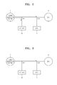
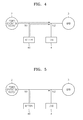
- FIGS. 2 through 8 are concept views showing various modes of the energy storage system shown in FIG. 1 .
- a portion of power generated by the power generation system 2 is used to charge the battery 40, and the remaining portion of the power generated by the power generation system 2 is supplied to the load 4 or to the grid 3.
- the UDC 10 performs power conversion, for example, as described above.
- the BDC 60 operates in a charging mode, whereas the INV 30 operates in a discharging mode.
- the present mode may be used when the amount of power generated by the power generation system 2 is very large. Furthermore, the present mode may be applied to when it is desired to charge the battery 40.
- power generated by the power generation system 2 may be distributed based on the charge state of the battery 40 and power supply required by the load 4.
- priority is given to charging the battery 40, a portion of power generated by the power generation system 2 that is needed to charge the battery 40 is supplied to the battery 40, and the remaining portion of the power generated by the power generation system 2 is supplied to the grid 3 or the load 4. For example, if the grid 3 is connected to the load 4, the grid 3 may supply any power to the load 4 still lacking despite the load 4 receiving power from the power generation system 2. Accordingly, in this mode, priority is given to charging the battery 40.
- power generated by the power generation system 2 is supplied to the load 4, and any remaining portion from the power generation system 2 is used to charge the battery 40.
- the grid 3 is not connected to the load 4
- power generated by the power generation system 2 is supplied to the load 4, and only excess power from the power generation system 2 is used to charge the battery 40.
- the UDC 10 performs power conversion. Furthermore, the BDC 60 stops operating, and the INV 30 operates in a discharging mode. In this mode, since power generated by the power generation system 2 is only supplied to the grid 3 or the load 4, the UDC 10 may operate in a MPPT control mode for generating power at peak efficiency. This mode may be applied based on whether it is necessary to charge the battery 40 and whether the amount of power generated by the power generation system 2 is greater than the amount of power consumed by the load 4.
- the UDC 10 performs power conversion.
- the INV 30 and the BDC 60 both operate in their respective discharging modes.
- the present mode may be applied, for example, when the battery 40 may discharge power and the amount of power consumed by the load 4 is greater than the amount of power generated by the power generation system 2. If power supplied from the power generation system 2 and the battery 40 are insufficient to satisfy the load 4, power of the grid 3 may be additionally supplied to the load 4.
- power from the power generation system 2 and the battery 40 may be supplied to the load 4.
- the power generation system 2 does not generate power, e.g., at night when the power generation system 2 is a solar power generation system. Since no power is generated by the power generation system 2, the UDC 10 stops operating. The INV 30 and the BDC 60 operate in their respective discharging modes.
- the present mode may be applied.
- the mode of FIG. 3 may be applied, for example, if the amount of power consumed by the load 4 is greater than that available from the grid 3.
- this mode may be applied to reduce costs by using power stored in the battery 40 during a time when the cost of power from the grid is high.
- the UDC 10 performs power conversion. Furthermore, the INV 30 stops operating, and the BDC 60 operates in a charging mode. The present mode may, for example, be applied when the battery 40 may no longer be discharged.
- the battery 40 is charged by power generated by the power generation system 2 and by power of the grid 3.
- the UDC 10 performs power conversion.
- the INV 30 and the BDC 60 operate in their respective charging modes.
- the grid 3 and the load 4 are connected, and this mode may be applied when the amount of power generated by the power generation system 2 is less than the amount of power to be charged in the battery 40.
- the battery 40 is with power from the grid 3.
- the power generation system 2 may not generate power at all. Since no power is generated by the power generation system 2, the UDC 10 stops operating.
- the INV 30 and the BDC 60 operate in their respective charging modes. Since power is received from the grid 3 in this mode, the grid 3 and the load 4 are connected, and this mode may be applied when the battery 40 may be charged.
- the energy storage system 1 may completely stop operations of the UDC 10, the INV 30, and the BDC 60 to minimized power consumption. However, in some embodiments, the energy storage system 1 continues to monitor the states of the power generation system 2, the grid 3, and the load 4.
- the energy storage system 1 may have various modes as described above. Hereinafter, a method of determining a mode for operation based on various conditions will be described.
- FIGS. 9 through 11 are flowcharts showing a method of controlling an energy storage system, according to some embodiments.
- the energy storage system 1 determines whether the load 4 is connected to the grid 3.
- the energy storage system 1 may prioritize charging the battery 40.
- the battery 40 may be used to perform a UPS function.
- the load 4 may not be connected to the grid 3, such as when any of various abnormalities, such as a power interruption, occurs.
- the energy storage system 1 may be controlled with priority given to supplying power to the load 4.
- the integrated controller 90 controls the energy storage system 1 to be in a mode for when the grid 3 and the load 4 are connected or to be in a mode for when the grid 3 and the load 4 are not connected.
- FIG. 10 is a flowchart showing a mode for when the grid 3 and the load 4 are connected.
- whether power is generated by the power generation system 2 is determined (operation S10). If power is generated by the power generation system 2, the charge state of the battery 40 is determined. For example, whether the charge state of the battery 40 is above a reference value, about 0.9 is determined (operation S11). The charge state of about 0.9 is a reference value indicating that the battery 40 is fully charged. However, the value is merely an example, and the present invention is not limited thereto.
- an amount of power Ppv generated by the power generation system 2 and an amount of power PL to be consumed by the load 4 are compared (operation S12). If PL is greater than Ppv, all power generated by the power generation system 2 is supplied to the load 4, the UDC 10 is turned on, and the BDC 60 and the INV 30 are set to operate in discharging modes. In addition, since the amount of power Ppv generated by the power generation system 2 is insufficient to satisfy the power PL to be consumed by the load 4, power of the grid 3 or power stored in the battery 40 may also be supplied to the load 4. If, however, PL is less than Ppv, all power supplied to the load 4 may be generated by the power generation system 2. Accordingly, the UDC 10 is turned on, and the INV 30 is set to operate in a discharging mode. Furthermore, the BDC 60 is not needed and is turned off.
- the BDC 60 is set to operate in a charging mode and the battery 40 is charged.
- whether Ppv is greater than the charging power of the battery 40 Pbc is determined (operation S13). If Ppv is greater than Pbc, only a portion of power generated by the power generation system 2 necessary to charge the battery 40 is supplied to the battery 40, and the remaining portion of the power generated by the power generation system 2 is supplied to the load 4. In this case, the UDC 10 is turned on, and the INV 30 is set to operate in a discharging mode. On the contrary, if Ppv is less than Pbc, power generated by the power generation system 2 is insufficient to charge the battery 40. Therefore, the INV 30 is set to operate in a charging mode, and the battery 40 is charged by using power from both the power generation system 2 and the grid 3.
- operation S10 If it is determined in operation S10 that no power is generated by the power generation system 2, the UDC 10 is turned off, and the charge state of the battery 40 is determined (operation S14). If the battery 40 is fully charged, a cost comparison is performed (operation S15). If the cost of the grid power Cgp is less than the cost of the energy storage system power Cessp, power from the grid 3 is used. In some embodiments, to compare the costs, the current time is determined.
- Cost of power supplied from the grid 3 may vary according to time of day. For example, the cost of off-peak electricity may be relatively inexpensive. Accordingly, operation S15 may be used to determine whether off-peak electricity from the grid 3 is available and less expensive than power from the energy storage system 1. When off-peak electricity from the grid 3 is available and less expensive, the load 4 uses power supplied from the grid 3, and thus components of the energy storage system 1 are turned off. However, as described above, in some embodiments, the integrated controller 90 continues monitoring operation. If however, power from the grid 3 is not less expensive than power from the energy storage system 1, power stored in the battery 40 is supplied to the load 4, and the BDC 60 and the INV 30 are set to operate in their respective discharging modes.
- the battery 40 is charged by receiving power from the grid 3.
- the BDC 60 and the INV 30 are set to operate in their respective charging modes.
- FIG. 11 is a flowchart showing a method for controlling the energy storage system 1 if the grid 3 and the load 4 are not connected.
- whether power is generated by the power generation system 2 is determined (operation S20). If power is generated by the power generation system 2, the amount of power Ppv generated by the power generation system 2 is compared with the amount of power PL needed by the load 4 (operations S21 and S22).
- the UDC 10 is turned on, the INV 30 is set to operate in a discharge mode, and power generated by the power generation system 2 is supplied to the load 4. Since power stored in the battery 40 is not used, the BDC 60 is turned off.
- the charge state of the battery 40 is determined (operation S23). If the charge state of the battery 40 is above 0.9, the UDC 10 is turned on, the INV 30 is set to operate in a discharging mode, and power generated by the power generation system 2 is supplied to the load 4. Since power stored in the battery 40 is not used, the BDC 60 is turned off. Because the load 4 and the grid 3 are not connected, and Ppv is greater than PL, surplus power is generated. Therefore, the UDC 10 stops performing an MPPT control operation and reduces the amount of power Ppv generated by the power generation system 2, such that the amount of power Ppv generated by the power generation system 2corresponds to amount of power PL consumed by the load 4.
- the charge state of the battery 40 is less than 0.9, it is beneficial to charge the battery 40.
- the UDC is turned on, the BDC 60 is set to operate in a charging mode, and the INV 30 is set to operate in a discharging mode. Since supplying power to the load 4 has priority, the power generated by the power generation system 2 corresponding to the amount of power PL consumed by the load 4 is supplied to the load 4, and the remaining portion of the power generated by the power generation system 2 is supplied to the battery 40.
- a charge state of 0.2 is a reference value indicating that the battery 40 is fully discharged. However, the value is merely an example, and the present invention is not limited thereto. If the charge state of the battery 40 is less than about 0.2, the amount of power Ppv generated by the power generation system 2 and an amount of power Pbc needed to charge the battery 40 are compared (operation S25). IF Ppv is greater than Pbc, the battery 40 is charged by using power generated by the power generation system 2. Therefore, the UDC 10 is turned on, and the BDC 60 is set to operate in a charging mode, and the INV 30 is turned off. However, if, in operation S25, Ppv is less than Pbc, power generated by the power generation system 2 is insufficient to supply the load 4 and to charge the battery 40, and all components of the energy storage system 1 are turned off.
- the charge state of the battery 40 is determined (operation S28), and, if the charge state of the battery 40 is below 0.2, all components of the energy storage system 1 are turned off. If, however, the charge state of the battery 40 is above 0.2, power stored in the battery 40 is supplied to the load 4. Accordingly, the BDC 60 and the INV 30 are set to operate in their respective discharging modes.
- the energy storage system 1 may operate in an optimal state based on the states of the power generation system 2, the load 4, and the grid 3.
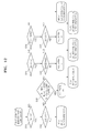
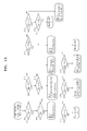
- FIGS. 12 and 13 are flowcharts showing methods of controlling an energy storage system, according to other embodiments. of the present invention.
- FIG. 12 is a flowchart showing a mode for when the grid 3 and the load 4 are connected.
- operation S31 whether power is generated by the power generation system 2 is determined. If power is generated by the power generation system 2, the charge state of the battery 40 is determined (operation S32). In operation 32, it is determined whether the charge state of the battery 40 is above a reference value indicating whether the battery 40 is fully discharged (operation S32). If the charge state of the battery 40 is above the reference value, the battery 40 is not charged even if the battery 40 is not fully charged. The priority may be to extend the lifespan of the battery 40 by reducing the amount of charging and discharging in the battery 40. In this case, all power generated by the power generation system 2 is supplied to the grid 3 and the load 4.
- the UDC 10 is turned on, the INV 30 is set to operate in a discharging mode, and the BDC 60 is turned off.
- the battery 40 should be charged.
- the current cost of grid power can be compared to the cost of power from the power generation system.
- the current time may be determined to determine whether the current time is at or near a time when off-peak electricity is available (operation S33). When the current time is at or near a time when off-peak electricity is available, e.g., within 30 minutes, all components of the energy storage system 1 are turned off until the current time is within the time when the off-peak electricity is supplied. However, if, in operation S33 the time when off-peak electricity is supplied is not near, the battery 40 is charged by receiving power generated by the power generation system 2. Accordingly, the UDC 10 is turned on, the BDC 60 is set to operate in a charging mode, and the INV 30 is turned off.
- the UDC 10 is turned off.
- the charge state of the battery 40 is determined (operation S34). If the charge state of the battery 40 is above the reference value indicating that the battery 40 is fully charged, the power needed by the load 4 PL is compared to the power available from the grid 3 PG (operation S35). If power supplied from the grid 3 is greater than the amount of power PL to be consumed by the load 4, all components of the energy storage system 1 are turned off. However, in the case that power supplied from the grid 3 does not satisfy the amount of power PL to be consumed by the load 4, power stored in the battery 40 is supplied to the load 4, and the BDC 60 and the INV 30 are set to operate in discharging modes.
- determining whether the power supplied from the grid 3 is greater than the amount of power PL to be consumed by the load 4 includes determining a current time and comparing the time with known times when the load 4 is expected to operate with peak demand or with power consumption greater than that available from the grid 3.
- the power needed by the load 4 PL is compared to the power available from the grid 3 PG (operation S36). If the power needed by the load 4 is not greater than the power available from the grid 3, the battery 40 is charged with power from the grid 3. The INV 30 and the BDC 60 are set to operate in their respective charging modes. However, if in operation S36 the power needed by the load 4 is greater than the power available from the grid 3, it is determined whether the charge state of the battery 40 is below the reference value indicating that the battery 40 is fully discharged (operation S37).
- the battery 40 may be discharged. Accordingly, since power supplied from the grid 3 does not satisfy the amount of power PL to be consumed by the load 4, power stored in the battery 40 is supplied to the load 4. At this point, the BDC 60 and the INV 30 are set to operate in their respective discharging modes.
- FIG. 13 is a flowchart showing an operation mode for when the grid 3 and the load 4 are not connected.
- operation S40 whether power is generated by the power generation system 2 is determined. If power is generated by the power generation system 2, the energy storage system 1 may operate according to operations S41 through S43. Operations S41 through S43 are the same as operations S21 through S23 of FIG. 11 , and thus detailed descriptions thereof are omitted.
- Ppv is below PL
- Ppv is compared with a minimum amount PLmin of power to be consumed by the load 4. If Ppv is greater than PLmin, power generated by the power generation system 2 is supplied to the load 4 so as to supply the minimum amount of power to the load 4. Accordingly, the UDC 10 is turned on, the INV 30 is set to operate in a discharging mode, and the BDC 60 is turned off. If Ppv is below PLmin, the charge state of the battery 40 is determined (operation S45). If the charge state of the battery 40 is greater than a reference value indicating that the battery 40 is fully discharged, power generated by the power generation system 2 and power stored in the battery 40 are supplied to the load 4. To accomplish this, the UDC 10 is turned on, and the BDC 60 and the INV 30 are set to operate in discharging modes.
- a DC link voltage Vlink is measured and compared to a reference voltage (operation S46).
- the DC link voltage Vlink may decrease when the amount of power PL to be consumed by the load 4 is greater than that which is supplied from the energy storage system 1 to the load 4.
- the reference voltage may be less than the DC link voltage at its proper functioning value. For example, if it is expected that the normal DC link voltage Vlink is 370V, the reference voltage may be 350V. If it is determined in operation S46 that the DC link voltage Vlink is below 350V, all components of the energy storage system 1 are turned off.
- the UDC 10 is turned off.
- the charge state of the battery 40 is determined (operations S47), and if the charge state of the battery 40 is below a reference value indicating that the battery 40 is fully discharged, all components of the energy storage system 1 are turned off.
- an amount of power Pbd discharged from the battery 40 and the amount of power PL to be consumed by the load 4 are compared (operation S48). If Pbd is less than PL, the amount of power Pbd discharged from the battery 40 and the minimum amount of power PLmin to be consumed by the load 4 are compared (operation S49). If Pbd is greater than or equal to PL, or if Pbd is greater than or equal to PLmin, power stored in the battery 40 is supplied to the load 4. To accomplish this, the BDC 60 and the INV 30 are set to operate in their respective discharging modes. If Pb is less than PLmin, power stored in the battery 40 is insufficient to satisfy the minimum amount of power PLmin to be consumed by the load 4, and all components of the energy storage system 1 are turned off.
- the energy storage system 1 may operate in an optimal state based on the states of the power generation system 2, the load 4, and the grid 3
- a computer program for implementing the above embodiments and modified embodiments may be recorded on a computer readable recording medium.
- the computer readable recording medium may be any data storage device that can store programs or data which can be thereafter read by a processor. Examples of the computer readable recording medium include semiconductor recording medium (e.g. flash memory), magnetic recording medium (e.g. ROM), hard disks, and so on.
- the recording medium may be read by a processor, e.g. the integrated controller 90 as shown in FIG. 1 , and the computer program may be executed by the processor.
Landscapes
- Engineering & Computer Science (AREA)
- Power Engineering (AREA)
- Charge And Discharge Circuits For Batteries Or The Like (AREA)
- Supply And Distribution Of Alternating Current (AREA)
- Secondary Cells (AREA)
- Control Of Electrical Variables (AREA)
Applications Claiming Priority (1)
| Application Number | Priority Date | Filing Date | Title |
|---|---|---|---|
| KR1020100051960A KR101174891B1 (ko) | 2010-06-01 | 2010-06-01 | 전력 저장 시스템 및 그 제어방법 |
Publications (2)
| Publication Number | Publication Date |
|---|---|
| EP2400621A2 true EP2400621A2 (fr) | 2011-12-28 |
| EP2400621A3 EP2400621A3 (fr) | 2014-11-26 |
Family
ID=44650934
Family Applications (1)
| Application Number | Title | Priority Date | Filing Date |
|---|---|---|---|
| EP20110161919 Withdrawn EP2400621A3 (fr) | 2010-06-01 | 2011-04-11 | Système de stockage d'énergie et son procédé de contrôle |
Country Status (5)
| Country | Link |
|---|---|
| US (1) | US8941263B2 (fr) |
| EP (1) | EP2400621A3 (fr) |
| JP (1) | JP5272040B2 (fr) |
| KR (1) | KR101174891B1 (fr) |
| CN (1) | CN102270884B (fr) |
Cited By (3)
| Publication number | Priority date | Publication date | Assignee | Title |
|---|---|---|---|---|
| US8552583B2 (en) | 2010-09-20 | 2013-10-08 | Industry-Academic Cooperation Foundation, Yonsei University | Power supply system and method including power generator and storage device |
| EP3017523B1 (fr) | 2013-07-03 | 2017-03-22 | SMA Solar Technology AG | Procédé de commande de convertisseur comportant une batterie ainsi que les convertisseurs comprtant une batterie qui sont bidirectionnels |
| EP3227982A1 (fr) * | 2014-12-02 | 2017-10-11 | Imeon Energy | Procédé pour la gestion d'énergie |
Families Citing this family (136)
| Publication number | Priority date | Publication date | Assignee | Title |
|---|---|---|---|---|
| KR101156535B1 (ko) * | 2010-01-18 | 2012-06-21 | 삼성에스디아이 주식회사 | 전력 저장 장치와 그 동작 방법 및 전력 저장 시스템 |
| KR101117706B1 (ko) * | 2010-07-28 | 2012-03-05 | 삼성에스디아이 주식회사 | 전력 공급 장치 |
| WO2012161255A1 (fr) * | 2011-05-24 | 2012-11-29 | 京セラ株式会社 | Dispositif de commande d'alimentation et procédé de commande d'alimentation |
| DK2528184T3 (da) * | 2011-05-25 | 2014-10-20 | Siemens Ag | Fremgangsmåde og indretning til styring af en jævnstrømstransmissionsforbindelse |
| US9494373B2 (en) * | 2011-06-06 | 2016-11-15 | Panasonic Intellectual Property Management Co., Ltd. | Heat pump operation method and heat pump system |
| JP5777965B2 (ja) * | 2011-07-22 | 2015-09-16 | 京セラ株式会社 | 故障診断方法、系統連系装置、及び制御装置 |
| JP5719714B2 (ja) * | 2011-07-22 | 2015-05-20 | 京セラ株式会社 | 起動制御方法、系統連系装置、及び制御装置 |
| JP5960958B2 (ja) * | 2011-07-27 | 2016-08-02 | 京セラ株式会社 | 電力管理システム |
| JP5376092B2 (ja) * | 2011-09-26 | 2013-12-25 | 日本電気株式会社 | 電力接続制御システム及び方法 |
| US20150318699A2 (en) * | 2011-09-29 | 2015-11-05 | James Frederick Wolter | Power generation system with integrated renewable energy generation, energy storage, and power control |
| DE102011056138A1 (de) * | 2011-12-07 | 2013-06-13 | Refusol Gmbh | System zur Nutzung und Speicherung elektrischer Energie verschiedenartiger Energiequellen |
| US9293923B2 (en) | 2011-12-19 | 2016-03-22 | Samsung Sdi Co., Ltd. | Energy storage system and controlling method of the same |
| JP6060515B2 (ja) | 2011-12-22 | 2017-01-18 | ソニー株式会社 | 電子機器および給電システム |
| WO2013097824A1 (fr) * | 2011-12-31 | 2013-07-04 | 深圳市比亚迪汽车研发有限公司 | Véhicule électrique et système d'alimentation et régulateur de moteur pour véhicule électrique |
| KR101323938B1 (ko) * | 2012-01-02 | 2013-10-31 | 엘에스산전 주식회사 | 전력 시스템 및 그 제어 방법 |
| US20130187464A1 (en) * | 2012-01-23 | 2013-07-25 | Seldon Energy Partners, LLC | System and Method for Portable Solar Array Deployment |
| JP6261866B2 (ja) * | 2012-01-27 | 2018-01-17 | 三菱重工業株式会社 | 発電設備及び電力貯蔵装置を備えた発電システム及びその制御方法並びにプログラム |
| CN102624035B (zh) * | 2012-03-29 | 2013-11-13 | 中国电力科学研究院 | 一种基于直流功率紧急控制的交直流协调控制方法 |
| US20150069845A1 (en) * | 2012-04-11 | 2015-03-12 | Siemens Aktiengesellschaft | Electric device and method for controlling an electric energy generator |
| SE542381C2 (sv) * | 2012-04-23 | 2020-04-21 | Brokk Ab | Elektiskt driven demoleringsrobot och dess kraftförsörjningssystem |
| US9231407B2 (en) * | 2012-05-07 | 2016-01-05 | Samsung Sdi Co., Ltd. | Battery system, method of controlling the same, and energy storage system including the battery system |
| CN102820668B (zh) * | 2012-05-18 | 2014-09-03 | 北京睿能世纪科技有限公司 | 一种控制储能系统出力的方法、装置及一种发电系统 |
| CN102664423B (zh) * | 2012-05-30 | 2014-09-17 | 山东大学 | 基于粒子群算法的风电场储能容量控制方法 |
| KR101337576B1 (ko) * | 2012-06-14 | 2013-12-06 | 이엔테크놀로지 주식회사 | Soc 관리를 위한 방법 및 시스템 |
| JP6013076B2 (ja) * | 2012-08-10 | 2016-10-25 | 京セラ株式会社 | エネルギー管理装置、エネルギー管理システムおよびエネルギー管理方法 |
| KR20140023125A (ko) | 2012-08-17 | 2014-02-26 | 엘지전자 주식회사 | 에너지 저장장치, 전력 관리 장치, 이동 단말기 및 그 동작방법 |
| JP2014050297A (ja) * | 2012-09-04 | 2014-03-17 | Sanken Electric Co Ltd | 電力供給システム |
| US9780564B2 (en) * | 2012-09-28 | 2017-10-03 | Eaton Corporation | Dual-input inverter and method of controlling same |
| WO2014049173A2 (fr) * | 2012-09-28 | 2014-04-03 | Nec Europe Ltd. | Procédé d'exploitation d'une entité de stockage d'énergie et d'un système de stockage d'énergie |
| KR101464411B1 (ko) * | 2012-11-21 | 2014-11-21 | 주식회사 포스코아이씨티 | 전력 관리 시스템 및 관리 방법 |
| KR101473896B1 (ko) * | 2013-03-14 | 2014-12-22 | 건국대학교 산학협력단 | 무정전 기능을 갖는 하이브리드 배전시스템 |
| JP5880778B2 (ja) * | 2013-03-20 | 2016-03-09 | 富士電機株式会社 | 太陽光発電システム |
| CN103219726A (zh) * | 2013-03-29 | 2013-07-24 | 浙江大学 | 一种基于储能的微电网拓扑结构 |
| JP6158562B2 (ja) * | 2013-04-01 | 2017-07-05 | 京セラ株式会社 | 電力変換装置、制御システム、及び制御方法 |
| KR101445738B1 (ko) * | 2013-04-30 | 2014-11-03 | 주식회사 케이디파워 | 전력 사용량 데이터베이스를 이용하여 전기에너지 저장량을 조정하는 전력저장 장치 및 그 운영 방법 |
| JP5835304B2 (ja) | 2013-06-04 | 2015-12-24 | 日本電気株式会社 | 電力供給システム、電力管理装置、電力管理方法および電力管理プログラム |
| KR101331183B1 (ko) * | 2013-06-17 | 2013-11-20 | 주식회사 이온 | 에너지저장 기능을 갖는 무정전전원장치 |
| KR102092088B1 (ko) * | 2013-07-04 | 2020-04-14 | 에스케이이노베이션 주식회사 | 전기저장장치 운전모드 제어 장치 및 방법 |
| JP6033438B2 (ja) | 2013-07-10 | 2016-11-30 | 三菱電機株式会社 | 電力制御システム |
| JP6268786B2 (ja) * | 2013-07-26 | 2018-01-31 | 住友電気工業株式会社 | パワーコンディショナ、パワーコンディショナシステムおよびパワーコンディショナの制御方法 |
| KR101517566B1 (ko) * | 2013-10-01 | 2015-05-06 | 동서대학교산학협력단 | 배터리 기반의 하이브리드 비상전원 발전기 |
| US9614457B2 (en) | 2013-10-18 | 2017-04-04 | Abb Schweiz Ag | Modular thyristor-based rectifier circuits |
| US9334749B2 (en) | 2013-10-18 | 2016-05-10 | Abb Technology Ag | Auxiliary power system for turbine-based energy generation system |
| US9577557B2 (en) | 2013-10-18 | 2017-02-21 | Abb Schweiz Ag | Turbine-generator system with DC output |
| KR101520262B1 (ko) * | 2013-10-22 | 2015-05-18 | 한국전기연구원 | 계통 연계형 충전방식의 무정전 전원공급장치 |
| KR101569144B1 (ko) * | 2013-10-30 | 2015-11-13 | 한전케이디엔주식회사 | 분산전원관리 장치 및 방법 |
| KR101523941B1 (ko) * | 2013-12-18 | 2015-05-29 | 전자부품연구원 | 에너지 저장 시스템 |
| JP6174478B2 (ja) * | 2013-12-24 | 2017-08-02 | 京セラ株式会社 | 電力制御装置、機器制御装置、及び方法 |
| TWI513140B (zh) * | 2014-01-06 | 2015-12-11 | 立錡科技股份有限公司 | 電源供應控制方法 |
| KR101469904B1 (ko) * | 2014-01-23 | 2014-12-09 | (주)에이비엠그린텍 | 에너지 저장장치가 구성된 태양광 발전 설비의 통합전력제어반 모드 제어시스템 |
| WO2015125715A1 (fr) * | 2014-02-24 | 2015-08-27 | シャープ株式会社 | Système électrique, dispositif de commande de charge et de décharge, et procédé de commande de charge et de décharge |
| CN104953607A (zh) * | 2014-03-25 | 2015-09-30 | 利思电气(上海)有限公司 | 一种有功馈能型电能质量发生装置 |
| KR101418103B1 (ko) | 2014-04-02 | 2014-07-11 | 에스피브이(주) | 다변화 신재생 전력 이용과 전력의 적정 저장 및 공급 기법이 적용된 효율적 에너지 관리 및 저장 시스템 |
| KR101476099B1 (ko) * | 2014-04-25 | 2014-12-24 | 한국수자원공사 | 3레벨 전력변환기를 이용한 하이브리드 무변압기형 무정전 전원장치 |
| KR101476100B1 (ko) * | 2014-04-25 | 2014-12-24 | 한국수자원공사 | 3레벨 전력변환기를 이용한 무정전 전원장치 |
| KR101599991B1 (ko) * | 2014-04-30 | 2016-03-07 | 고려대학교 산학협력단 | 복합 발전 시스템 |
| CN104065157B (zh) * | 2014-06-09 | 2017-02-15 | 深圳微网能源管理系统实验室有限公司 | 一种改进供电可靠性的不间断电源 |
| KR102335059B1 (ko) * | 2014-09-15 | 2021-12-06 | 주식회사 탑 엔지니어링 | 배터리 관리 시스템 및 이를 이용한 배터리 팩 용량의 가변적 분배 방법 |
| TWI532296B (zh) * | 2014-11-19 | 2016-05-01 | 盈正豫順電子股份有限公司 | 雙端口能量儲存系統及其控制方法 |
| JP6475002B2 (ja) * | 2014-11-21 | 2019-02-27 | 田淵電機株式会社 | 蓄電池付き分散型電源システム |
| CN107258042A (zh) * | 2014-12-03 | 2017-10-17 | 清洁动力解决方案有限公司 | 能量管理装置和电气设备 |
| CN105846421B (zh) * | 2015-01-12 | 2018-08-14 | 国家电网公司 | 一种提高电力系统暂态稳定性的储能容量配置方法 |
| KR101677831B1 (ko) | 2015-02-11 | 2016-11-18 | 엘에스산전 주식회사 | 배터리 에너지 저장 시스템을 포함하는 전력 공급 시스템 |
| US10913506B2 (en) | 2015-03-09 | 2021-02-09 | Young Hui HUR | Generator for bicycle, and battery module attachable/detachable to/from generator |
| KR101729832B1 (ko) * | 2015-04-02 | 2017-04-24 | 엘에스산전 주식회사 | 에너지 저장 시스템의 제어 방법 |
| WO2016181617A1 (fr) | 2015-05-13 | 2016-11-17 | パナソニックIpマネジメント株式会社 | Dispositif de commande de charge/décharge |
| KR101776997B1 (ko) * | 2015-05-19 | 2017-09-08 | 주식회사 엘지씨엔에스 | Dc 마이크로그리드 시스템 및 그 제어 방법 |
| US11065968B2 (en) * | 2015-07-20 | 2021-07-20 | Auckland Uniservices Limited | Integrated multi-source IPT system |
| JP6741933B2 (ja) * | 2015-10-02 | 2020-08-19 | ミツミ電機株式会社 | 光走査モジュール、光走査制御装置 |
| CN105403766B (zh) * | 2015-10-26 | 2018-01-23 | 珠海格力电器股份有限公司 | 机组电量消耗的确定方法和装置 |
| CN105305497A (zh) * | 2015-11-20 | 2016-02-03 | 施剑鸿 | 一种低损耗智能电网的管理系统及方法 |
| KR101805273B1 (ko) * | 2015-12-29 | 2017-12-06 | 주식회사 포스코아이씨티 | 온라인 ups 기능이 내장된 에너지 저장 시스템 및 그 동작 방법 |
| ITUB20160473A1 (it) * | 2016-02-05 | 2017-08-05 | Sira Soc Per L Informatica La Ricerca E Lautomazione Soc A Responsabilita Limitata | Sistema di controllo e gestione energetica |
| US9866063B2 (en) * | 2016-04-05 | 2018-01-09 | Nuscale Power, Llc | Fault-tolerant power distribution systems for a modular power plant |
| KR101656437B1 (ko) * | 2016-04-27 | 2016-09-09 | 에디슨솔라이텍(주) | 무정전 기능을 갖는 부하 평준화용 전력 저장 시스템의 제어방법 |
| KR101666533B1 (ko) * | 2016-04-28 | 2016-10-14 | 주식회사 대경산전 | 에너지 제어 시스템 |
| US10411500B2 (en) * | 2016-06-16 | 2019-09-10 | Yu Qin | Electric vehicle fast charging station with solar energy system and its method |
| US9871396B2 (en) | 2016-06-21 | 2018-01-16 | General Electric Company | System and method for controlling charge of an energy storage device from a renewable energy source |
| KR101727060B1 (ko) * | 2016-06-22 | 2017-04-17 | 네오피스 주식회사 | 비상발전기와 에너지 저장장치를 포함하는 통합 전력관리 시스템 |
| KR101843543B1 (ko) * | 2016-07-26 | 2018-03-30 | 주식회사 성삼 | 하이브리드 전력 저장 시스템 및 이의 전력 운용 방법 |
| CN106091450B (zh) * | 2016-07-27 | 2018-04-10 | 重庆京天能源投资(集团)股份有限公司 | 智能化供能微网 |
| US10833529B2 (en) * | 2016-10-11 | 2020-11-10 | Commscope Technologies Llc | Systems and methods for high efficiency power conversion |
| KR101735749B1 (ko) * | 2016-10-18 | 2017-05-15 | 세방전기 주식회사 | 3상 4선식 계통 연계형-독립형 겸용 인버터 |
| KR101904846B1 (ko) | 2016-12-09 | 2018-10-10 | 효성중공업 주식회사 | Ess 최적 효율 운영방법 |
| KR101741830B1 (ko) * | 2017-01-05 | 2017-05-31 | (주)티에스 | 무정전전원장치 및 그 방법 |
| US11532939B1 (en) * | 2017-01-09 | 2022-12-20 | Alarm.Com Incorporated | Solar energy management |
| EP3346578A3 (fr) | 2017-01-10 | 2018-09-26 | Solaredge Technologies Ltd. | Système d'alimentation en courant continu autonome et procédé |
| US20180248390A1 (en) * | 2017-02-24 | 2018-08-30 | Jeremiah Couloute | System and method for managing power |
| US20180287388A1 (en) * | 2017-03-30 | 2018-10-04 | Rheem Manufacturing Company | Controlled Distribution of Integrated Power Supplies for Electrical Loads |
| US11686595B2 (en) * | 2017-05-01 | 2023-06-27 | Ara Petrosyan | Assembly, system, and method for distributing, monitoring, and controlling electrical power |
| JP6593855B2 (ja) * | 2017-05-09 | 2019-10-23 | 合同会社チュラエコネット | 太陽光発電設備 |
| KR102074686B1 (ko) | 2017-05-19 | 2020-02-07 | 엘에스산전 주식회사 | 하이브리드 에너지 저장 시스템 |
| KR102299604B1 (ko) * | 2017-08-10 | 2021-09-07 | 엘에스일렉트릭(주) | 에너지 저장 시스템 |
| US20190067986A1 (en) * | 2017-08-25 | 2019-02-28 | Saudi Arabian Oil Company | Distributed Energy Storage Systems |
| KR101977165B1 (ko) * | 2017-11-08 | 2019-05-10 | 와이피피 주식회사 | 비상 전원용 ess 제어 시스템, 방법, 및 상기 방법을 실행시키기 위한 컴퓨터 판독 가능한 프로그램을 기록한 기록 매체 |
| KR101859939B1 (ko) * | 2017-11-28 | 2018-05-21 | 디아이케이(주) | 발전 레퍼런스를 추종하는 태양광/ess 장치의 에너지 관리 시스템 및 그 제어방법 |
| US11594883B2 (en) * | 2018-01-23 | 2023-02-28 | Tdk Corporation | Direct current power supplying system |
| EP3782253A1 (fr) * | 2018-04-19 | 2021-02-24 | Flexgen Power Systems, Inc. | Appareil et procédés d'interconnexion de réseau souple d'actifs de production décentralisée d'énergie |
| KR102019087B1 (ko) * | 2018-06-07 | 2019-09-06 | (주)다쓰테크 | 태양광 발전 에너지 저장시스템의 제어방법 |
| KR101952419B1 (ko) * | 2018-06-15 | 2019-02-26 | (주)귀뚜라미 | 발전 기능을 가진 가스히트펌프시스템을 이용한 에너지 통합 제어 시스템 및 방법 |
| KR102211067B1 (ko) * | 2018-06-22 | 2021-02-02 | (주)다쓰테크 | 에너지 저장 시스템, 그리고 에너지 저장 시스템을 이용한 최대전력 추종 방법 |
| EP3624292B1 (fr) * | 2018-09-11 | 2021-06-23 | Bayerische Motoren Werke Aktiengesellschaft | Procédé et dispositif de commande pour faire fonctionner un accumulateur d'énergie électrique stationnaire qui est prévu pour une unité de consommation électrique, telle qu'un appareil ménager, par exemple |
| WO2020058172A1 (fr) | 2018-09-17 | 2020-03-26 | Richter R & W - Steuerungstechnik GmbH | Système de commande/régulation d'un réseau électrique et module de commande/régulation d'un système de commande/régulation d'un réseau électrique |
| DE102018215777B4 (de) * | 2018-09-17 | 2021-08-26 | Richter R & W - Steuerungstechnik GmbH | Steuer/Regelmodul für ein Steuer/Regel-System für ein Stromnetz |
| KR102223230B1 (ko) * | 2018-10-08 | 2021-03-05 | 주식회사 시너젠 | Amp를 이용한 하이브리드 마이크로 그리드 시스템 |
| CN111386654B (zh) * | 2018-10-29 | 2023-08-04 | 东芝三菱电机产业系统株式会社 | 风力发电系统及电力转换装置 |
| US11183938B2 (en) | 2018-11-14 | 2021-11-23 | Toshiba International Corporation | Hybrid PV inverter with SCIB battery integration |
| KR102205262B1 (ko) * | 2018-11-21 | 2021-01-20 | 스칸젯매크론 주식회사 | 자가발전이 가능한 스마트 알람 경보시스템 |
| JP7261977B2 (ja) * | 2018-11-30 | 2023-04-21 | パナソニックIpマネジメント株式会社 | 制御システム、電力システム、制御方法及びプログラム |
| CN109638953B (zh) * | 2018-12-17 | 2020-10-09 | 珠海格力电器股份有限公司 | 供电控制方法、装置、存储介质及供电设备 |
| KR20200125785A (ko) * | 2019-04-25 | 2020-11-05 | 호남대학교 산학협력단 | 제로에너지 빌딩에서의 전력 모니터링 시스템 |
| KR102127731B1 (ko) * | 2019-07-23 | 2020-06-29 | 주식회사 에니트 | 지능형 배전반 및 이를 이용한 전력 제어방법 |
| KR102151109B1 (ko) * | 2019-08-28 | 2020-09-02 | 주식회사 티에스이에스 | Ac/dc 하이브리드 분전반 시스템 |
| KR102294482B1 (ko) * | 2019-09-11 | 2021-08-30 | 한국광기술원 | 태양광 발전 시스템의 충전 장치 및 방법 |
| CN110739713B (zh) * | 2019-09-27 | 2021-03-05 | 福建星云电子股份有限公司 | 一种智能储能充电一体化装置及其充放电控制方法 |
| EP3809470A1 (fr) | 2019-10-15 | 2021-04-21 | Solaredge Technologies Ltd. | Procédé et appareil permettant de faire fondre la neige |
| WO2021149477A1 (fr) * | 2020-01-22 | 2021-07-29 | 京セラ株式会社 | Dispositif de commande d'accumulateur, procédé de commande d'accumulateur et programme de commande d'accumulateur |
| KR102136504B1 (ko) * | 2020-02-07 | 2020-07-21 | (주)위 에너지 | 무정전 전력 공급 관리 시스템 |
| EP4136410A4 (fr) * | 2020-04-13 | 2024-09-18 | Petrosyan, Ara | Ensemble, système et procédé permettant de distribuer, de surveiller et de réguler l'énergie électrique |
| KR102402372B1 (ko) * | 2020-05-29 | 2022-05-26 | 재단법인 포항산업과학연구원 | 축전식 탈염 모듈의 태양광 모듈 연계 전력 변환 시스템, 이를 이용한 에너지 회생 방법 및 컴퓨터로 독출 가능한 기록 매체 |
| KR102223422B1 (ko) * | 2020-08-06 | 2021-03-05 | 대농산업전기(주) | 무정전 전원 공급 장치 및 그의 제어 방법 |
| KR102539509B1 (ko) * | 2020-12-15 | 2023-06-05 | 재단법인 포항산업과학연구원 | 축전식 탈염 모듈의 태양광 모듈 연계 전력 변환 시스템, 이를 이용한 에너지 회생 방법 및 컴퓨터로 독출 가능한 기록 매체 |
| ES3047724T3 (en) * | 2021-02-26 | 2025-12-04 | Huawei Digital Power Tech Co Ltd | Energy system, and charging and discharging control method |
| KR102556290B1 (ko) * | 2021-03-05 | 2023-07-17 | 순천향대학교 산학협력단 | 홈 에너지 관리 시스템 |
| KR102350667B1 (ko) * | 2021-04-08 | 2022-01-12 | 주식회사 신의테크 | 송전 전력 계통 기반의 전력 계통 관제 시스템 |
| KR102793991B1 (ko) | 2021-10-06 | 2025-04-09 | 주식회사 엘지에너지솔루션 | 태양광 시스템과 연계하는 에너지 저장 시스템 및 에너지 저장 시스템의 제어 방법 |
| KR102756218B1 (ko) * | 2022-02-03 | 2025-01-21 | 주식회사 포드림 | 정해진 주기에 따라 에너지저장장치(ess)와 무정전전원공급장치(ups)의 역할을 절체하는 자동절체장치를 포함하는 ess-ups겸용 전기 에너지 공급 장치 |
| TWI842153B (zh) * | 2022-10-25 | 2024-05-11 | 岳鼎智慧能源股份有限公司 | 電力控制系統及電力控制方法 |
| KR102678463B1 (ko) * | 2022-11-15 | 2024-06-26 | 주식회사 넥스트스퀘어 | 전력 방향성을 갖는 직류 전력계통용 스위칭 장치의 제어방법 |
| CN115864484B (zh) * | 2022-11-23 | 2024-04-09 | 国网湖北综合能源服务有限公司 | 多能互补直流微网的功率能量控制方法 |
| KR102662264B1 (ko) * | 2022-11-29 | 2024-05-03 | 주식회사 이엔에스 | Pv-ess 분산전원용 스마트 에지 미터 |
| KR102876767B1 (ko) * | 2023-02-28 | 2025-10-28 | 케빈랩 주식회사 | 전력 공급 시스템 |
| KR102854606B1 (ko) * | 2023-07-04 | 2025-09-03 | 이상선 | 스마트 그리드 운영 시스템 |
| KR102666164B1 (ko) * | 2023-12-01 | 2024-05-14 | 주식회사 입실론엑스 | 전력 공급 기술 및 이를 이용하는 데이터 센터 |
| KR102722827B1 (ko) * | 2024-02-27 | 2024-10-25 | 김태성 | 나노 그리드용 전력 변환 장치 |
| KR102918643B1 (ko) * | 2024-10-08 | 2026-01-27 | 한국생산기술연구원 | 그리드 포밍 인버터를 활용한 계통 연계형 발전 시스템 및 그 제어 방법 |
Family Cites Families (23)
| Publication number | Priority date | Publication date | Assignee | Title |
|---|---|---|---|---|
| JPH11127546A (ja) | 1997-10-23 | 1999-05-11 | Mitsubishi Electric Corp | 太陽光発電システム |
| JP2003079054A (ja) | 2001-08-31 | 2003-03-14 | Sanyo Electric Co Ltd | 蓄電池を備えた太陽光発電システム |
| JP2003348768A (ja) * | 2002-05-24 | 2003-12-05 | Matsushita Electric Ind Co Ltd | 無停電電源装置 |
| JP2004180467A (ja) * | 2002-11-29 | 2004-06-24 | Hitachi Home & Life Solutions Inc | 系統連系形電源システム |
| KR100475830B1 (ko) | 2002-12-20 | 2005-03-10 | 한국수자원공사 | 무인 관측국의 자동 전원 공급장치 |
| US7117044B2 (en) * | 2003-12-30 | 2006-10-03 | Square D Company | Alternative energy system control method and apparatus |
| JP3759151B1 (ja) | 2004-11-17 | 2006-03-22 | 株式会社正興電機製作所 | 電力貯蔵システム |
| KR100817137B1 (ko) | 2006-04-20 | 2008-03-27 | 한국전기연구원 | 분산발전 시스템의 전력변환장치 및 이를 이용한 절체방법 |
| JP2007295680A (ja) | 2006-04-24 | 2007-11-08 | Matsushita Electric Ind Co Ltd | 負荷制御装置 |
| GB0615562D0 (en) * | 2006-08-04 | 2006-09-13 | Ceres Power Ltd | Power supply control for power |
| JP5124114B2 (ja) * | 2006-08-28 | 2013-01-23 | シャープ株式会社 | 蓄電機能を有するパワーコンディショナ |
| JP4967608B2 (ja) | 2006-11-07 | 2012-07-04 | 株式会社明電舎 | 分散電源システム |
| KR100866097B1 (ko) * | 2007-01-10 | 2008-10-30 | 건국대학교 산학협력단 | 계통연계형 태양광 발전시스템 및 그 운용방법 |
| JP5110913B2 (ja) * | 2007-02-28 | 2012-12-26 | 三洋電機株式会社 | 電源装置 |
| JP4628386B2 (ja) | 2007-03-20 | 2011-02-09 | 財団法人電力中央研究所 | 分散電源の運転状況検出装置、電力量計及び配電系統の制御装置 |
| US8063606B2 (en) * | 2007-05-11 | 2011-11-22 | Research In Motion Limited | Battery charger for a handheld computing device and an external battery |
| US20100017045A1 (en) * | 2007-11-30 | 2010-01-21 | Johnson Controls Technology Company | Electrical demand response using energy storage in vehicles and buildings |
| JP5209957B2 (ja) | 2007-12-26 | 2013-06-12 | パナソニック株式会社 | 直流配電システム |
| US9007024B2 (en) * | 2008-05-28 | 2015-04-14 | American Reliance, Inc. | DC power control to maximize battery charging time |
| WO2009155445A2 (fr) | 2008-06-18 | 2009-12-23 | Premium Power Corporation | Systèmes de production et de stockage d'énergie renouvelable intégrés et procédés associés |
| US8110941B2 (en) * | 2009-02-25 | 2012-02-07 | International Business Machines Corporation | Power demand management method and system |
| KR101084214B1 (ko) * | 2009-12-03 | 2011-11-18 | 삼성에스디아이 주식회사 | 계통 연계형 전력 저장 시스템 및 전력 저장 시스템 제어 방법 |
| KR100961834B1 (ko) * | 2010-01-29 | 2010-06-08 | 김동집 | 복수의 전력 공급원으로 구동되는 전원 공급장치의 제어 장치 및 방법 |
-
2010
- 2010-06-01 KR KR1020100051960A patent/KR101174891B1/ko active Active
-
2011
- 2011-01-12 US US13/005,112 patent/US8941263B2/en active Active
- 2011-04-11 EP EP20110161919 patent/EP2400621A3/fr not_active Withdrawn
- 2011-04-14 CN CN201110096175.3A patent/CN102270884B/zh active Active
- 2011-05-09 JP JP2011104470A patent/JP5272040B2/ja active Active
Non-Patent Citations (1)
| Title |
|---|
| None |
Cited By (3)
| Publication number | Priority date | Publication date | Assignee | Title |
|---|---|---|---|---|
| US8552583B2 (en) | 2010-09-20 | 2013-10-08 | Industry-Academic Cooperation Foundation, Yonsei University | Power supply system and method including power generator and storage device |
| EP3017523B1 (fr) | 2013-07-03 | 2017-03-22 | SMA Solar Technology AG | Procédé de commande de convertisseur comportant une batterie ainsi que les convertisseurs comprtant une batterie qui sont bidirectionnels |
| EP3227982A1 (fr) * | 2014-12-02 | 2017-10-11 | Imeon Energy | Procédé pour la gestion d'énergie |
Also Published As
| Publication number | Publication date |
|---|---|
| JP5272040B2 (ja) | 2013-08-28 |
| KR20110132122A (ko) | 2011-12-07 |
| US20110291479A1 (en) | 2011-12-01 |
| CN102270884B (zh) | 2015-12-16 |
| US8941263B2 (en) | 2015-01-27 |
| CN102270884A (zh) | 2011-12-07 |
| JP2011254696A (ja) | 2011-12-15 |
| EP2400621A3 (fr) | 2014-11-26 |
| KR101174891B1 (ko) | 2012-08-17 |
Similar Documents
| Publication | Publication Date | Title |
|---|---|---|
| US8941263B2 (en) | Energy storage system and method of controlling the same | |
| KR101097265B1 (ko) | 전력 저장 시스템 및 그 제어방법 | |
| US8810066B2 (en) | Power storage system and method of controlling the same | |
| KR101193168B1 (ko) | 전력 저장 시스템, 그 제어방법 및 이를 실행시키기 위한 프로그램을 저장한 기록매체 | |
| KR101146670B1 (ko) | 에너지 관리 시스템 및 이의 제어 방법 | |
| KR101084215B1 (ko) | 에너지 저장 시스템 및 이의 제어 방법 | |
| US8575780B2 (en) | Power storage apparatus, method of operating the same, and power storage system | |
| EP3148037B1 (fr) | Systeme de stockage d'energie | |
| US8552590B2 (en) | Energy management system and grid-connected energy storage system including the energy management system | |
| KR101156533B1 (ko) | 에너지 저장 시스템 및 이의 제어 방법 | |
| KR101369633B1 (ko) | 전력 저장 시스템 및 그 제어방법 | |
| KR101084216B1 (ko) | 에너지 저장 시스템 및 이의 제어 방법 | |
| US20130088900A1 (en) | Energy storage system and controlling method of the same | |
| US20110210614A1 (en) | Power storage system and method of controlling the same | |
| KR20130099022A (ko) | 에너지 저장 시스템용 전력 변환 시스템 및 이의 제어방법 | |
| KR20120111406A (ko) | 배터리 시스템 및 이를 포함하는 에너지 저장 시스템 | |
| KR20150106694A (ko) | 에너지 저장 시스템과 그의 구동방법 | |
| KR20140013553A (ko) | 하이브리드 발전 시스템 | |
| KR20140058770A (ko) | 전력 관리 시스템의 동작 모드 결정 방법 및 시스템 | |
| Chakraborty et al. | Coordinated Frequency Based Demand Side Management Scheme with Active Power Curtailment of Solar PV in a Battery Hybrid Stand-Alone Microgrid | |
| KR20140041156A (ko) | 전력 변환 장치 |
Legal Events
| Date | Code | Title | Description |
|---|---|---|---|
| AK | Designated contracting states |
Kind code of ref document: A2 Designated state(s): AL AT BE BG CH CY CZ DE DK EE ES FI FR GB GR HR HU IE IS IT LI LT LU LV MC MK MT NL NO PL PT RO RS SE SI SK SM TR |
|
| AX | Request for extension of the european patent |
Extension state: BA ME |
|
| PUAI | Public reference made under article 153(3) epc to a published international application that has entered the european phase |
Free format text: ORIGINAL CODE: 0009012 |
|
| 17P | Request for examination filed |
Effective date: 20120321 |
|
| PUAL | Search report despatched |
Free format text: ORIGINAL CODE: 0009013 |
|
| AK | Designated contracting states |
Kind code of ref document: A3 Designated state(s): AL AT BE BG CH CY CZ DE DK EE ES FI FR GB GR HR HU IE IS IT LI LT LU LV MC MK MT NL NO PL PT RO RS SE SI SK SM TR |
|
| AX | Request for extension of the european patent |
Extension state: BA ME |
|
| RIC1 | Information provided on ipc code assigned before grant |
Ipc: H02J 3/32 20060101ALI20141021BHEP Ipc: H02J 9/06 20060101ALI20141021BHEP Ipc: H02J 3/38 20060101AFI20141021BHEP Ipc: H02J 7/35 20060101ALI20141021BHEP |
|
| STAA | Information on the status of an ep patent application or granted ep patent |
Free format text: STATUS: THE APPLICATION HAS BEEN WITHDRAWN |
|
| 18W | Application withdrawn |
Effective date: 20160106 |