EP2400636B1 - Moteur électrique à courant alternatif pouvant être branché dans le circuit de charge de batteries - Google Patents
Moteur électrique à courant alternatif pouvant être branché dans le circuit de charge de batteries Download PDFInfo
- Publication number
- EP2400636B1 EP2400636B1 EP11305804.4A EP11305804A EP2400636B1 EP 2400636 B1 EP2400636 B1 EP 2400636B1 EP 11305804 A EP11305804 A EP 11305804A EP 2400636 B1 EP2400636 B1 EP 2400636B1
- Authority
- EP
- European Patent Office
- Prior art keywords
- phase
- coils
- electric motor
- winding
- stator
- Prior art date
- Legal status (The legal status is an assumption and is not a legal conclusion. Google has not performed a legal analysis and makes no representation as to the accuracy of the status listed.)
- Active
Links
Images


Classifications
-
- H—ELECTRICITY
- H02—GENERATION; CONVERSION OR DISTRIBUTION OF ELECTRIC POWER
- H02K—DYNAMO-ELECTRIC MACHINES
- H02K3/00—Details of windings
- H02K3/46—Fastening of windings on the stator or rotor structure
-
- H—ELECTRICITY
- H02—GENERATION; CONVERSION OR DISTRIBUTION OF ELECTRIC POWER
- H02K—DYNAMO-ELECTRIC MACHINES
- H02K3/00—Details of windings
- H02K3/04—Windings characterised by the conductor shape, form or construction, e.g. with bar conductors
- H02K3/28—Layout of windings or of connections between windings
-
- B—PERFORMING OPERATIONS; TRANSPORTING
- B60—VEHICLES IN GENERAL
- B60K—ARRANGEMENT OR MOUNTING OF PROPULSION UNITS OR OF TRANSMISSIONS IN VEHICLES; ARRANGEMENT OR MOUNTING OF PLURAL DIVERSE PRIME-MOVERS IN VEHICLES; AUXILIARY DRIVES FOR VEHICLES; INSTRUMENTATION OR DASHBOARDS FOR VEHICLES; ARRANGEMENTS IN CONNECTION WITH COOLING, AIR INTAKE, GAS EXHAUST OR FUEL SUPPLY OF PROPULSION UNITS IN VEHICLES
- B60K6/00—Arrangement or mounting of plural diverse prime-movers for mutual or common propulsion, e.g. hybrid propulsion systems comprising electric motors and internal combustion engines
- B60K6/20—Arrangement or mounting of plural diverse prime-movers for mutual or common propulsion, e.g. hybrid propulsion systems comprising electric motors and internal combustion engines the prime-movers consisting of electric motors and internal combustion engines, e.g. HEVs
- B60K6/22—Arrangement or mounting of plural diverse prime-movers for mutual or common propulsion, e.g. hybrid propulsion systems comprising electric motors and internal combustion engines the prime-movers consisting of electric motors and internal combustion engines, e.g. HEVs characterised by apparatus, components or means specially adapted for HEVs
- B60K6/26—Arrangement or mounting of plural diverse prime-movers for mutual or common propulsion, e.g. hybrid propulsion systems comprising electric motors and internal combustion engines the prime-movers consisting of electric motors and internal combustion engines, e.g. HEVs characterised by apparatus, components or means specially adapted for HEVs characterised by the motors or the generators
-
- B—PERFORMING OPERATIONS; TRANSPORTING
- B60—VEHICLES IN GENERAL
- B60L—PROPULSION OF ELECTRICALLY-PROPELLED VEHICLES; SUPPLYING ELECTRIC POWER FOR AUXILIARY EQUIPMENT OF ELECTRICALLY-PROPELLED VEHICLES; ELECTRODYNAMIC BRAKE SYSTEMS FOR VEHICLES IN GENERAL; MAGNETIC SUSPENSION OR LEVITATION FOR VEHICLES; MONITORING OPERATING VARIABLES OF ELECTRICALLY-PROPELLED VEHICLES; ELECTRIC SAFETY DEVICES FOR ELECTRICALLY-PROPELLED VEHICLES
- B60L53/00—Methods of charging batteries, specially adapted for electric vehicles; Charging stations or on-board charging equipment therefor; Exchange of energy storage elements in electric vehicles
- B60L53/20—Methods of charging batteries, specially adapted for electric vehicles; Charging stations or on-board charging equipment therefor; Exchange of energy storage elements in electric vehicles characterised by converters located in the vehicle
- B60L53/24—Using the vehicle's propulsion converter for charging
-
- B—PERFORMING OPERATIONS; TRANSPORTING
- B60—VEHICLES IN GENERAL
- B60L—PROPULSION OF ELECTRICALLY-PROPELLED VEHICLES; SUPPLYING ELECTRIC POWER FOR AUXILIARY EQUIPMENT OF ELECTRICALLY-PROPELLED VEHICLES; ELECTRODYNAMIC BRAKE SYSTEMS FOR VEHICLES IN GENERAL; MAGNETIC SUSPENSION OR LEVITATION FOR VEHICLES; MONITORING OPERATING VARIABLES OF ELECTRICALLY-PROPELLED VEHICLES; ELECTRIC SAFETY DEVICES FOR ELECTRICALLY-PROPELLED VEHICLES
- B60L2220/00—Electrical machine types; Structures or applications thereof
- B60L2220/50—Structural details of electrical machines
- B60L2220/54—Windings for different functions
-
- Y—GENERAL TAGGING OF NEW TECHNOLOGICAL DEVELOPMENTS; GENERAL TAGGING OF CROSS-SECTIONAL TECHNOLOGIES SPANNING OVER SEVERAL SECTIONS OF THE IPC; TECHNICAL SUBJECTS COVERED BY FORMER USPC CROSS-REFERENCE ART COLLECTIONS [XRACs] AND DIGESTS
- Y02—TECHNOLOGIES OR APPLICATIONS FOR MITIGATION OR ADAPTATION AGAINST CLIMATE CHANGE
- Y02T—CLIMATE CHANGE MITIGATION TECHNOLOGIES RELATED TO TRANSPORTATION
- Y02T10/00—Road transport of goods or passengers
- Y02T10/60—Other road transportation technologies with climate change mitigation effect
- Y02T10/64—Electric machine technologies in electromobility
-
- Y—GENERAL TAGGING OF NEW TECHNOLOGICAL DEVELOPMENTS; GENERAL TAGGING OF CROSS-SECTIONAL TECHNOLOGIES SPANNING OVER SEVERAL SECTIONS OF THE IPC; TECHNICAL SUBJECTS COVERED BY FORMER USPC CROSS-REFERENCE ART COLLECTIONS [XRACs] AND DIGESTS
- Y02—TECHNOLOGIES OR APPLICATIONS FOR MITIGATION OR ADAPTATION AGAINST CLIMATE CHANGE
- Y02T—CLIMATE CHANGE MITIGATION TECHNOLOGIES RELATED TO TRANSPORTATION
- Y02T10/00—Road transport of goods or passengers
- Y02T10/60—Other road transportation technologies with climate change mitigation effect
- Y02T10/70—Energy storage systems for electromobility, e.g. batteries
-
- Y—GENERAL TAGGING OF NEW TECHNOLOGICAL DEVELOPMENTS; GENERAL TAGGING OF CROSS-SECTIONAL TECHNOLOGIES SPANNING OVER SEVERAL SECTIONS OF THE IPC; TECHNICAL SUBJECTS COVERED BY FORMER USPC CROSS-REFERENCE ART COLLECTIONS [XRACs] AND DIGESTS
- Y02—TECHNOLOGIES OR APPLICATIONS FOR MITIGATION OR ADAPTATION AGAINST CLIMATE CHANGE
- Y02T—CLIMATE CHANGE MITIGATION TECHNOLOGIES RELATED TO TRANSPORTATION
- Y02T10/00—Road transport of goods or passengers
- Y02T10/60—Other road transportation technologies with climate change mitigation effect
- Y02T10/7072—Electromobility specific charging systems or methods for batteries, ultracapacitors, supercapacitors or double-layer capacitors
-
- Y—GENERAL TAGGING OF NEW TECHNOLOGICAL DEVELOPMENTS; GENERAL TAGGING OF CROSS-SECTIONAL TECHNOLOGIES SPANNING OVER SEVERAL SECTIONS OF THE IPC; TECHNICAL SUBJECTS COVERED BY FORMER USPC CROSS-REFERENCE ART COLLECTIONS [XRACs] AND DIGESTS
- Y02—TECHNOLOGIES OR APPLICATIONS FOR MITIGATION OR ADAPTATION AGAINST CLIMATE CHANGE
- Y02T—CLIMATE CHANGE MITIGATION TECHNOLOGIES RELATED TO TRANSPORTATION
- Y02T90/00—Enabling technologies or technologies with a potential or indirect contribution to GHG emissions mitigation
- Y02T90/10—Technologies relating to charging of electric vehicles
- Y02T90/12—Electric charging stations
-
- Y—GENERAL TAGGING OF NEW TECHNOLOGICAL DEVELOPMENTS; GENERAL TAGGING OF CROSS-SECTIONAL TECHNOLOGIES SPANNING OVER SEVERAL SECTIONS OF THE IPC; TECHNICAL SUBJECTS COVERED BY FORMER USPC CROSS-REFERENCE ART COLLECTIONS [XRACs] AND DIGESTS
- Y02—TECHNOLOGIES OR APPLICATIONS FOR MITIGATION OR ADAPTATION AGAINST CLIMATE CHANGE
- Y02T—CLIMATE CHANGE MITIGATION TECHNOLOGIES RELATED TO TRANSPORTATION
- Y02T90/00—Enabling technologies or technologies with a potential or indirect contribution to GHG emissions mitigation
- Y02T90/10—Technologies relating to charging of electric vehicles
- Y02T90/14—Plug-in electric vehicles
Definitions
- the present invention relates to an alternating current electric motor of a combined electric supply and charging device for supplying an electric motor or an alternator with rechargeable batteries.
- the invention will advantageously find an application in the field of electric or hybrid motor vehicles in which the batteries can supply the engine via an inverter and be recharged when the automobile is stopped by means of an alternative electrical network.
- the electrical device according to the invention may be used in other fields and in particular in energy generation devices of the wind or hydraulic type.
- an electric or hybrid vehicle comprises a traction chain formed by high-voltage rechargeable batteries delivering a direct current to an inverter which transforms this direct current into an alternating current making it possible to power an electric motor, of the rotating electric machine type, this the latter ensuring the movement of the vehicle.
- an on-board charging device essentially comprising an AC-DC converter making it possible to rectify the AC power of the domestic electrical network into DC power to charge the batteries.
- the charging device can also include a power factor corrector pre-regulator whose role is to limit the rejection of harmonics on the electrical network.
- the battery charging device uses the inverter to form a continuous AC converter as well as the motor windings to form the inductors.
- the passage from the motor supply mode to the battery charge mode is ensured by switching means with power contactors by disconnecting the neutral.
- the use of the motor phases as an inductor to rectify the current from the electrical network causes disturbances at the level of the motor rotor.
- the inductors are magnetized by the alternating currents of the electric network thus creating magnetic fields. These magnetic fields act on the rotor which can move, for example by vibrating, and even, depending on the magnetic fields and the characteristics of the rotor, enter in rotation.
- This setting in motion poses both comfort and safety problems in the case of using the combined electric device in an electric vehicle even if the latter can be equipped with a system for decoupling the train from the machine during load.
- one solution consists in carrying out static compensation consisting in injecting the load current into at least one winding of the stator connected to a phase of the network using an additional connection point, called the midpoint.
- a stator winding conventionally comprises a plurality of coils formed by a plurality of turns.
- the midpoint separates the phase winding of the stator into two parts so that the load current, injected via the midpoint, is divided into two currents flowing in opposite directions through each half-winding, each half-winding having the same number of turns.
- Too low an inductance of the motor has the consequence of making the control of the load currents difficult, in particular because of the large undulations of the current at the switching frequency.
- the present invention aims to propose an electric motor with alternating current for a device making it possible to supply the electric motor, and to recharge batteries using elements of the supply chain, that is to say elements of the motor and of the inverter, and such that the electric motor comprises a stator winding making it possible to obtain an apparent inductance at the midpoint sufficiently large to overcome the aforementioned drawbacks while eliminating the setting in motion of the rotor in charge mode.
- the invention provides an electric motor according to claim 1.
- the coils coupled, or even strongly coupled, between them are placed on the same side with respect to the connection point. In other words, the coils coupled, or even strongly coupled, between them belong to the same half-winding.
- the non-coupled, or even weakly coupled, coils between them are placed in different sides relative to the connection point. In other words, the non-coupled, or even weakly coupled, coils between them belong to different half-coils.
- each coil is distributed over several notches.
- Two coils of a phase belonging to different half-coils are distributed on notches located on either side of the connection point.
- each half-winding comprises at least two coils wound in opposite directions with respect to each other so as to reduce the magnetic coupling between the two half-coils of a phase.
- each half-winding comprises an even number of coils, each coil having a corresponding coil wound in the opposite direction.
- the winding mode according to the invention makes it possible to obtain a high value of the apparent inductance in load mode at the connection point while avoiding the setting in motion of the rotor in load mode.
- the decoupling of the half-windings of each phase of the stator thus makes it possible to improve the charging of the batteries of the device as well as the control of the charging current.
- the apparent inductance during charging is increased and is greater than a leakage inductance of the coils.
- the apparent inductance corresponds to a useful inductance of the motor.
- the apparent inductance at the connection point in charge mode is between 1 mH and 100 mH.
- the invention also relates to a combined electrical power supply and charging device comprising an alternating current electric motor according to the invention connected to an electrical network, an inverter and means for accumulating electrical energy.
- the electrical device also includes a DC-DC converter.
- the figure 1 generally illustrates a combined electrical charging and supply device 100 formed by rechargeable batteries 110, an inverter 120 and an electric motor 130 according to the invention making it possible both to recharge the rechargeable batteries 110 from a network electric 200 three-phase in charge mode and to supply the three-phase electric motor for its rotation in supply mode.
- the inverter has an H-shaped bridge structure for each phase of the motor, thus making it possible to maintain the connection of the neutral of each phase of the motor when charging the batteries; however, the inverter can be, more conventionally, an inverter produced with three-phase bridges and switching means of the power contactor type to switch from the battery charge mode 110 to the motor supply mode 130.
- the device 100 may also include a DC / DC converter 140 (DC-DC) between the inverter 120 and the batteries 110 allowing the voltage of the electrical supply network 200 to be adapted to the characteristics of the batteries 110 and to optimize dimensioning of the inverter 120 without degrading the efficiency of the device 100.
- DC-DC DC / DC converter 140
- the device 100 also includes connecting means 150 for connecting the device 100 to the electrical network 200 when the batteries need to be recharged.
- the electric motor 130 of the alternating current type, formed by a rotor and a stator, as well as on the winding mode of the stator of the alternating current motor 130.
- the rotor of the motor can be either a permanent magnet rotor, an excitation coil rotor or a squirrel cage.
- stator of an AC electric motor 130 of a combined charging and supply device 100 comprises at least two windings which are connected to the phases of the electrical network when the device 100 is in charging mode.
- the stator comprises two phase windings and in the case of a three-phase load network, the stator comprises at least three phase windings.
- Three-phase motors being the most widespread motors in the industry and in motor vehicle traction systems as illustrated in the figure 1 , we will mainly describe different winding modes of a three-phase motor.
- the invention is not limited to a three-phase motor and it is applicable by analogy to a polyphase motor or to a single-phase motor.
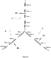
- the figure 2 is a diagram representing a first winding principle of a three-phase motor stator, the three phases of which are denoted A, B and C, integrating connection points A0, B0, C0 for injecting the load current and making it possible to get rid of rotor movements in load mode.
- the stator is wound so that each phase of the stator connected to a phase of the network is formed by a plurality 2n of coils wired in series. Each of the coils of each phase participating in the formation of the different poles of the stator.
- connection points A0, B0, C0 are positioned so that they separate each phase winding A, B, C into two half-windings or two half-coils respectively having two connection points a-a ', b-b ', cc' advantageously connected to the branches of the inverter 120 as illustrated in figure 1 .
- connection points A0, B0, C0 are the midpoints of each phase winding and are positioned so that each of the two groups of coils has n coils in series and the same number of turns.
- each half-winding of a phase A, B, C comprises a plurality of coils wired together so as to reduce the magnetic coupling of each half-winding at the connection point A0, B0, C0 so that 'there is a non-zero apparent inductance at the mid-point in charge mode.
- the apparent inductance is greater than the leakage inductance of the coils.
- the coils are wired as shown in figure 3 .
- the figure 3 illustrates the winding mode described previously in figure 2 on a three-phase stator with two pairs of poles with distributed winding on two notches.
- each pole is formed by the association of a coil of each phase comprising two turns.
- the figure 3 also illustrates how to connect the midpoints A0, B0, C0 on each phase A, B, C according to the winding mode described in figure 2 .
- the three-phase charging current of component 2 i A , 2 i B , 2 i C is injected on each phase of the stator connected with the three-phase network via the midpoints A0, B0, C0 and is distributed according to the arrows illustrated in figure 3 .
- the figure 11 presents an example of distributed winding.
- a first winding is supplied by its terminals A10, A11.
- a second winding is supplied by its terminals A20, A21.
- the two windings do not have a common connection point.
- the figure 12 presents an example of distributed winding with a connection point O according to the prior art.
- a current supplied to the connection point O is divided into a first current flowing in a first half-winding to exit at terminal a, and a second current flowing in a second half-winding to exit at terminal a '. It is observed that coils belonging to different half-coils are located on the same side with respect to the connection point O. These coils are strongly coupled but belong to different half-coils. So the example of winding in figure 12 does not make it possible to obtain an apparent inductance greater than a leakage inductance of the coils.
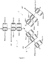
- the figure 4 is a diagram representing a second principle of winding a stator of a three-phase motor, the three phases of which are denoted A ', B' and C ', integrating midpoints A0', B0 ', C0' for injection of the charging current and making it possible to overcome the movements of the rotor in charging mode.
- the stator winding consists in connecting n 'groups of coils in series, each of the n' groups of coils being formed by a plurality n of coils wired in parallel.
- the connection points of the ends of the phase windings a-a ', b-b', cc 'are advantageously connected to the branches of the inverter 120 as illustrated in the figure 1 .
- each half-winding of a phase A, B, C comprises a plurality of coils wired together so as to reduce the magnetic coupling of each half-winding at the connection point A0, B0, C0 so that 'there is a non-zero apparent inductance at the mid-point in charge mode.
- the apparent inductance is greater than the leakage inductance of the coils.
- the coils are wired as shown in figure 5 , 6 , 7 , 8 , or 9 .
- the series-parallel winding as illustrated thus makes it possible to magnetically decouple the two half-windings on either side of the midpoint.
- the mutual inductance of the two half-windings is low, which makes it possible to obtain an apparent inductance at the high mid-point necessary for the load mode.
- the decoupling of the half-windings can also be increased or decreased by moving the physical half-windings apart or closer together on the stator so that the reluctance of the stator iron intervenes in the decoupling of the two half-windings.
- the points visible near the coils define the winding direction of the winding in the notches provided for this purpose on the stator.
- the figure 6 schematically represents a stator 300 wired according to the example of the figure 5 whose coils of the first half-winding are diametrically separated from the coils of the second half-winding.
- the reference L1 represents the mutual flow between two coils A1, A2 separated by a quarter turn in the indirect direction and the reference L2 represents the mutual flow between two coils A1, A3 diametrically opposite.
- the reluctance between the two diametrically opposite coils A1, A3 is greater than that between the two coils A1, A2 separated by a quarter turn in the indirect direction.
- the mutual flow L1 is therefore greater than the mutual flow L2.
- phase A the coils A1, A2 belong to the same half-winding, while the diametrically opposite coils A1, A3 belong to different half-coils.
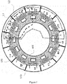
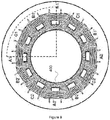
- the decoupling of the two half-windings can be increased by adding air gaps on the stator 400 as illustrated in the figure 7 .
- the figure 7 presents an example of an electric motor according to the invention comprising a stator wired according to the wiring example illustrated in the figure 5 .
- the air gaps are defined by shims 170, preferably made of a non-magnetic or non-metallic material. The length of the shims 170 determines the width of the air gaps.
- phase A the air gaps increase the reluctance between the coils A1 and A3 compared to the example in figure 6 .
- the coils A1 and A3 are even more loosely coupled than in the example of the figure 6 .
- the magnetic coupling of each half-winding at the connection point is therefore reduced compared to the example in figure 6 .
- the design of the rotor can also participate in addition to the decoupling of the two half-windings, in particular by the openings necessary for the location of the magnets, by the presence of air gap or even by voluntary openings added in the rotor in order to increase the reluctance between the two stator half-windings.
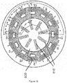
- the figure 10 presents an example of an electric motor according to the invention in which the design of the rotor 600 participates in the decoupling of the two half-windings of a phase.
- the rotor 600 includes openings 610 arranged in a radial direction.
- the openings 610 include magnets.
- the coils are wired as in the figure 5 .
- the openings 610 increase the reluctance between the coils A1 and A3 compared to the example in figure 6 .
- the coils A1 and A3 are even more loosely coupled than in the example of the figure 6 .
- the magnetic coupling of each half-winding at the connection point is therefore reduced compared to the example in figure 6 .
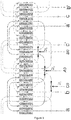
- the figure 8 is a diagram representing a third principle of winding a stator of a three-phase motor, the three phases of which are denoted A “, B” and C ", integrating midpoints A0", B0 ", C0" for injection of the charging current and making it possible to overcome the movements of the rotor in charging mode.
- the coils In each half-winding, the coils have fluxes which compensate each other thanks to the winding of the coils in the opposite direction within the half-winding. Thus, the coupling of each half-winding at the phase connection point is reduced, or even zero.
- phase A in a half-winding, the coils are wound in the opposite direction.
- the coils of a half-winding are traversed by the same current.
- the flux from the coil A1 compensates for that from the coil A1 '
- the flux from the coil A2 compensates for that from the coil A2'.
- the magnetic coupling of each half-winding at the connection point A0 is therefore reduced, or even zero.
- the illustrated winding makes it possible to obtain a stator whose phases are magnetically independent, which makes it possible to obtain a zero mutual inductance between the phases.
- This winding requires a stator having twice as many teeth as a stator with a conventional winding, but the diameter of the stator remains preserved because each tooth has twice as few turns as a conventional winding.
- Such a winding is shown on a stator 500 with two pairs of poles, each half-winding of which is magnetically independent of the second with reference to the figure 9 .
- the invention has mainly been described for a three-phase motor; however, the invention is also applicable by transposition to a polyphase electric machine.
- the invention has mainly been described with a domestic electrical network of the three-phase type; however, the invention is also applicable by transposition to a single-phase electrical network.
- the invention has mainly been described for an application in an electric motor vehicle; however, the invention may be used in other fields and in particular in energy generation devices of the wind or hydraulic type.
Landscapes
- Engineering & Computer Science (AREA)
- Power Engineering (AREA)
- Transportation (AREA)
- Mechanical Engineering (AREA)
- Chemical & Material Sciences (AREA)
- Combustion & Propulsion (AREA)
- Electric Propulsion And Braking For Vehicles (AREA)
- Windings For Motors And Generators (AREA)
- Control Of Ac Motors In General (AREA)
- Charge And Discharge Circuits For Batteries Or The Like (AREA)
- Secondary Cells (AREA)
Applications Claiming Priority (1)
| Application Number | Priority Date | Filing Date | Title |
|---|---|---|---|
| FR1055084A FR2961970B1 (fr) | 2010-06-25 | 2010-06-25 | Moteur electrique a courant alternatif d'un dispositif electrique combine d'alimentation et de charge |
Publications (2)
| Publication Number | Publication Date |
|---|---|
| EP2400636A1 EP2400636A1 (fr) | 2011-12-28 |
| EP2400636B1 true EP2400636B1 (fr) | 2020-04-22 |
Family
ID=43795042
Family Applications (1)
| Application Number | Title | Priority Date | Filing Date |
|---|---|---|---|
| EP11305804.4A Active EP2400636B1 (fr) | 2010-06-25 | 2011-06-24 | Moteur électrique à courant alternatif pouvant être branché dans le circuit de charge de batteries |
Country Status (8)
| Country | Link |
|---|---|
| US (1) | US8629636B2 (pt) |
| EP (1) | EP2400636B1 (pt) |
| JP (1) | JP5940770B2 (pt) |
| KR (1) | KR101900099B1 (pt) |
| CN (1) | CN102332766B (pt) |
| BR (1) | BRPI1102954A2 (pt) |
| CA (1) | CA2744779A1 (pt) |
| FR (1) | FR2961970B1 (pt) |
Families Citing this family (13)
| Publication number | Priority date | Publication date | Assignee | Title |
|---|---|---|---|---|
| FR2944391B1 (fr) * | 2008-11-18 | 2013-03-22 | Valeo Sys Controle Moteur Sas | Procede et dispositif electrique combine d'alimentation et de charge a moyens de compensation |
| DE102012202764A1 (de) * | 2012-02-23 | 2013-08-29 | Siemens Aktiengesellschaft | Ladevorrichtung eines elektrisch betriebenen Fahrzeugs |
| JP6139256B2 (ja) * | 2013-05-10 | 2017-05-31 | 株式会社東芝 | 回転電機の電機子巻線 |
| DE102014204956A1 (de) * | 2014-03-18 | 2015-09-24 | Robert Bosch Gmbh | Verfahren zur Erkennung von Anomalien in einer Batteriezelle und Kurzschlusssensorik |
| US9193273B1 (en) * | 2014-06-15 | 2015-11-24 | Efficient Drivetrains, Inc. | Vehicle with AC-to-DC inverter system for vehicle-to-grid power integration |
| FR3028683B1 (fr) | 2014-11-17 | 2017-12-29 | Lohr Electromecanique | Procede de recharge de moyens d'accumulation d'energie equipant un vehicule electrique ou hybride |
| DE102016218304B3 (de) * | 2016-09-23 | 2018-02-01 | Volkswagen Aktiengesellschaft | Vorrichtung zur Spannungswandlung, Traktionsnetz und Verfahren zum Laden einer Batterie |
| DE102018203134A1 (de) * | 2018-03-02 | 2019-09-05 | Zf Friedrichshafen Ag | Antriebsvorrichtung mit Transformationsfunktion, Antriebssystem und Verfahren zum Betreiben einer Antriebsvorrichtung |
| JP2019164638A (ja) * | 2018-03-20 | 2019-09-26 | 本田技研工業株式会社 | 情報提供装置、情報提供システム、及び情報提供方法 |
| KR102194406B1 (ko) | 2018-11-29 | 2020-12-24 | 경북대학교 산학협력단 | 충전 어셈블리 |
| WO2020242444A1 (en) | 2019-05-24 | 2020-12-03 | Huawei Technologies Co., Ltd. | Integrated charger and motor control system comprising a transformer and multi-level power converters |
| CN113815462A (zh) * | 2021-09-24 | 2021-12-21 | 上汽通用五菱汽车股份有限公司 | 新能源汽车充电管理方法、装置及计算机可读存储介质 |
| CN115962708B (zh) * | 2023-01-12 | 2026-04-21 | 中国人民解放军海军工程大学 | 基于柔性电路线圈的磁轴承定转子气隙测量方法 |
Citations (2)
| Publication number | Priority date | Publication date | Assignee | Title |
|---|---|---|---|---|
| EP0289292A2 (en) * | 1987-04-27 | 1988-11-02 | Dana Corporation | Variable reluctance motor |
| EP0994555A2 (en) * | 1998-10-16 | 2000-04-19 | Elevadores Atlas S/A | Subsynchronous reluctance electrical machine |
Family Cites Families (13)
| Publication number | Priority date | Publication date | Assignee | Title |
|---|---|---|---|---|
| FR1270277A (fr) * | 1960-10-11 | 1961-08-25 | Nat Res Dev | Moteur à vitesse continuement variable par modulation d'amplitude de pôles |
| US5264736A (en) * | 1992-04-28 | 1993-11-23 | Raytheon Company | High frequency resonant gate drive for a power MOSFET |
| JP3178146B2 (ja) | 1992-12-25 | 2001-06-18 | 富士電機株式会社 | 電気自動車の電気システム |
| FR2738411B1 (fr) | 1995-08-30 | 1997-10-17 | Renault | Systeme d'alimentation electrique mixte onduleur et convertisseur alternatif-continu |
| JP2002199639A (ja) * | 1996-02-23 | 2002-07-12 | Matsushita Electric Ind Co Ltd | 電動機 |
| JP2003333811A (ja) * | 2002-05-12 | 2003-11-21 | Yoshimitsu Okawa | 軸方向に分割された複数の固定子巻線を有する誘導電動機 |
| FR2844646B1 (fr) * | 2002-09-17 | 2006-02-24 | Denso Corp | Machine rotative electrique a haute tension |
| JP3864878B2 (ja) * | 2002-09-17 | 2007-01-10 | 株式会社デンソー | 高電圧回転電機 |
| CN100454725C (zh) * | 2004-08-06 | 2009-01-21 | 中国人民解放军海军工程大学 | 多相整流/三相辅助励磁控制的高速感应发电机 |
| CN2775919Y (zh) * | 2005-04-07 | 2006-04-26 | 董常发 | 直流电焊、发电、充电多用机 |
| JP2008109796A (ja) * | 2006-10-26 | 2008-05-08 | Toyota Motor Corp | 回転電機の巻線構造 |
| FR2944391B1 (fr) * | 2008-11-18 | 2013-03-22 | Valeo Sys Controle Moteur Sas | Procede et dispositif electrique combine d'alimentation et de charge a moyens de compensation |
| CN101741161A (zh) * | 2009-12-31 | 2010-06-16 | 华北电力大学 | 一种稀土永磁电动机及其控制方法 |
-
2010
- 2010-06-25 FR FR1055084A patent/FR2961970B1/fr not_active Expired - Fee Related
-
2011
- 2011-06-23 CA CA2744779A patent/CA2744779A1/en not_active Abandoned
- 2011-06-24 US US13/168,061 patent/US8629636B2/en not_active Expired - Fee Related
- 2011-06-24 EP EP11305804.4A patent/EP2400636B1/fr active Active
- 2011-06-24 BR BRPI1102954-4A patent/BRPI1102954A2/pt not_active Application Discontinuation
- 2011-06-27 JP JP2011141323A patent/JP5940770B2/ja not_active Expired - Fee Related
- 2011-06-27 CN CN201110268074.XA patent/CN102332766B/zh active Active
- 2011-06-27 KR KR1020110062303A patent/KR101900099B1/ko active Active
Patent Citations (2)
| Publication number | Priority date | Publication date | Assignee | Title |
|---|---|---|---|---|
| EP0289292A2 (en) * | 1987-04-27 | 1988-11-02 | Dana Corporation | Variable reluctance motor |
| EP0994555A2 (en) * | 1998-10-16 | 2000-04-19 | Elevadores Atlas S/A | Subsynchronous reluctance electrical machine |
Also Published As
| Publication number | Publication date |
|---|---|
| US8629636B2 (en) | 2014-01-14 |
| FR2961970A1 (fr) | 2011-12-30 |
| KR101900099B1 (ko) | 2018-09-18 |
| BRPI1102954A2 (pt) | 2015-07-28 |
| CN102332766B (zh) | 2016-01-13 |
| FR2961970B1 (fr) | 2017-03-10 |
| KR20120000543A (ko) | 2012-01-02 |
| JP5940770B2 (ja) | 2016-06-29 |
| EP2400636A1 (fr) | 2011-12-28 |
| US20110316454A1 (en) | 2011-12-29 |
| CA2744779A1 (en) | 2011-12-25 |
| CN102332766A (zh) | 2012-01-25 |
| JP2012070613A (ja) | 2012-04-05 |
Similar Documents
| Publication | Publication Date | Title |
|---|---|---|
| EP2400636B1 (fr) | Moteur électrique à courant alternatif pouvant être branché dans le circuit de charge de batteries | |
| EP2367705B1 (fr) | Procede et dispositif electrique combine d'alimentation et de charge a moyens de compensation | |
| EP2367704B1 (fr) | Dispositif electrique combine d'alimentation et de charge | |
| EP1609226B1 (fr) | Machine electrique synchrone comportant un stator et au moins un retor et dispositif de commande associe | |
| FR2947115A1 (fr) | Machine dynamoelectrique | |
| EP3365970B1 (fr) | Démarreur-générateur de turbomachine a machine électrique asynchrone multi-enroulements | |
| JP2012070613A5 (pt) | ||
| EP3183795B1 (fr) | Chargeur de batterie pour un véhicule automobile électrique ou hybride à haute intégration | |
| FR3084796A1 (fr) | Convertisseur de tension continu-continu a resonance | |
| FR3030931A1 (fr) | Machine electrique a excitation separee avec au moins deux induits et un inducteur | |
| FR2967529A1 (fr) | Machine electrique a bobinage dentaire a phases regroupees | |
| EP3175530B1 (fr) | Chargeur et procédé de charge de batterie de véhicule automobile électrique ou hybride a machine a reluctance variable a double saillance | |
| EP2592743B1 (fr) | Convertisseur pour circuit électrique destiné à fournir de l'énergie électrique de propulsion à bord d'un véhicule automobile | |
| CA2897891C (fr) | Dispositif electrique pour le stockage d'electricite par volant d'inertie | |
| EP2870684B1 (fr) | Machine electrique tournante a compensation de reaction magnetique d'induit | |
| EP3860875B1 (fr) | Systeme embarque et procede de conversion de puissance moyenne tension pour engin de transport | |
| FR3073102A1 (fr) | Rotor de machine electrique rotative | |
| EP2702667B1 (fr) | Dispositif et procédé de conversion reversible de puissance électrique multifonction | |
| WO2021019179A1 (fr) | Piste de recharge inductive pour véhicules électrifiés et système de recharge dynamique l'incorporant | |
| FR3014611A1 (fr) | Dispositif de charge pour vehicule electrique avec une chaine de traction a machine a reluctance commutee | |
| FR3166340A1 (fr) | Systeme electrique de transfert de puissance comportant un convertisseur ac-dc bidirectionnel | |
| EP1735898A2 (fr) | Coupleur electromagnetique de transmission electrique de puissance et dispositif de transmission comportant un tel coupleur |
Legal Events
| Date | Code | Title | Description |
|---|---|---|---|
| AK | Designated contracting states |
Kind code of ref document: A1 Designated state(s): AL AT BE BG CH CY CZ DE DK EE ES FI FR GB GR HR HU IE IS IT LI LT LU LV MC MK MT NL NO PL PT RO RS SE SI SK SM TR |
|
| AX | Request for extension of the european patent |
Extension state: BA ME |
|
| PUAI | Public reference made under article 153(3) epc to a published international application that has entered the european phase |
Free format text: ORIGINAL CODE: 0009012 |
|
| 17P | Request for examination filed |
Effective date: 20120628 |
|
| STAA | Information on the status of an ep patent application or granted ep patent |
Free format text: STATUS: EXAMINATION IS IN PROGRESS |
|
| 17Q | First examination report despatched |
Effective date: 20170927 |
|
| RAP1 | Party data changed (applicant data changed or rights of an application transferred) |
Owner name: VALEO SIEMENS EAUTOMOTIVE FRANCE SAS |
|
| GRAP | Despatch of communication of intention to grant a patent |
Free format text: ORIGINAL CODE: EPIDOSNIGR1 |
|
| STAA | Information on the status of an ep patent application or granted ep patent |
Free format text: STATUS: GRANT OF PATENT IS INTENDED |
|
| RIC1 | Information provided on ipc code assigned before grant |
Ipc: H02K 3/28 20060101AFI20191011BHEP Ipc: B60L 53/24 20190101ALI20191011BHEP |
|
| INTG | Intention to grant announced |
Effective date: 20191119 |
|
| GRAS | Grant fee paid |
Free format text: ORIGINAL CODE: EPIDOSNIGR3 |
|
| GRAA | (expected) grant |
Free format text: ORIGINAL CODE: 0009210 |
|
| STAA | Information on the status of an ep patent application or granted ep patent |
Free format text: STATUS: THE PATENT HAS BEEN GRANTED |
|
| AK | Designated contracting states |
Kind code of ref document: B1 Designated state(s): AL AT BE BG CH CY CZ DE DK EE ES FI FR GB GR HR HU IE IS IT LI LT LU LV MC MK MT NL NO PL PT RO RS SE SI SK SM TR |
|
| REG | Reference to a national code |
Ref country code: GB Ref legal event code: FG4D Free format text: NOT ENGLISH |
|
| REG | Reference to a national code |
Ref country code: CH Ref legal event code: EP |
|
| REG | Reference to a national code |
Ref country code: DE Ref legal event code: R096 Ref document number: 602011066371 Country of ref document: DE |
|
| REG | Reference to a national code |
Ref country code: IE Ref legal event code: FG4D Free format text: LANGUAGE OF EP DOCUMENT: FRENCH |
|
| REG | Reference to a national code |
Ref country code: AT Ref legal event code: REF Ref document number: 1261440 Country of ref document: AT Kind code of ref document: T Effective date: 20200515 |
|
| REG | Reference to a national code |
Ref country code: LT Ref legal event code: MG4D |
|
| REG | Reference to a national code |
Ref country code: NL Ref legal event code: MP Effective date: 20200422 |
|
| PG25 | Lapsed in a contracting state [announced via postgrant information from national office to epo] |
Ref country code: NO Free format text: LAPSE BECAUSE OF FAILURE TO SUBMIT A TRANSLATION OF THE DESCRIPTION OR TO PAY THE FEE WITHIN THE PRESCRIBED TIME-LIMIT Effective date: 20200722 Ref country code: GR Free format text: LAPSE BECAUSE OF FAILURE TO SUBMIT A TRANSLATION OF THE DESCRIPTION OR TO PAY THE FEE WITHIN THE PRESCRIBED TIME-LIMIT Effective date: 20200723 Ref country code: IS Free format text: LAPSE BECAUSE OF FAILURE TO SUBMIT A TRANSLATION OF THE DESCRIPTION OR TO PAY THE FEE WITHIN THE PRESCRIBED TIME-LIMIT Effective date: 20200822 Ref country code: PT Free format text: LAPSE BECAUSE OF FAILURE TO SUBMIT A TRANSLATION OF THE DESCRIPTION OR TO PAY THE FEE WITHIN THE PRESCRIBED TIME-LIMIT Effective date: 20200824 Ref country code: LT Free format text: LAPSE BECAUSE OF FAILURE TO SUBMIT A TRANSLATION OF THE DESCRIPTION OR TO PAY THE FEE WITHIN THE PRESCRIBED TIME-LIMIT Effective date: 20200422 Ref country code: NL Free format text: LAPSE BECAUSE OF FAILURE TO SUBMIT A TRANSLATION OF THE DESCRIPTION OR TO PAY THE FEE WITHIN THE PRESCRIBED TIME-LIMIT Effective date: 20200422 Ref country code: SE Free format text: LAPSE BECAUSE OF FAILURE TO SUBMIT A TRANSLATION OF THE DESCRIPTION OR TO PAY THE FEE WITHIN THE PRESCRIBED TIME-LIMIT Effective date: 20200422 Ref country code: FI Free format text: LAPSE BECAUSE OF FAILURE TO SUBMIT A TRANSLATION OF THE DESCRIPTION OR TO PAY THE FEE WITHIN THE PRESCRIBED TIME-LIMIT Effective date: 20200422 |
|
| REG | Reference to a national code |
Ref country code: AT Ref legal event code: MK05 Ref document number: 1261440 Country of ref document: AT Kind code of ref document: T Effective date: 20200422 |
|
| PG25 | Lapsed in a contracting state [announced via postgrant information from national office to epo] |
Ref country code: HR Free format text: LAPSE BECAUSE OF FAILURE TO SUBMIT A TRANSLATION OF THE DESCRIPTION OR TO PAY THE FEE WITHIN THE PRESCRIBED TIME-LIMIT Effective date: 20200422 Ref country code: LV Free format text: LAPSE BECAUSE OF FAILURE TO SUBMIT A TRANSLATION OF THE DESCRIPTION OR TO PAY THE FEE WITHIN THE PRESCRIBED TIME-LIMIT Effective date: 20200422 Ref country code: RS Free format text: LAPSE BECAUSE OF FAILURE TO SUBMIT A TRANSLATION OF THE DESCRIPTION OR TO PAY THE FEE WITHIN THE PRESCRIBED TIME-LIMIT Effective date: 20200422 Ref country code: BG Free format text: LAPSE BECAUSE OF FAILURE TO SUBMIT A TRANSLATION OF THE DESCRIPTION OR TO PAY THE FEE WITHIN THE PRESCRIBED TIME-LIMIT Effective date: 20200722 |
|
| PG25 | Lapsed in a contracting state [announced via postgrant information from national office to epo] |
Ref country code: AL Free format text: LAPSE BECAUSE OF FAILURE TO SUBMIT A TRANSLATION OF THE DESCRIPTION OR TO PAY THE FEE WITHIN THE PRESCRIBED TIME-LIMIT Effective date: 20200422 |
|
| REG | Reference to a national code |
Ref country code: DE Ref legal event code: R097 Ref document number: 602011066371 Country of ref document: DE |
|
| PG25 | Lapsed in a contracting state [announced via postgrant information from national office to epo] |
Ref country code: ES Free format text: LAPSE BECAUSE OF FAILURE TO SUBMIT A TRANSLATION OF THE DESCRIPTION OR TO PAY THE FEE WITHIN THE PRESCRIBED TIME-LIMIT Effective date: 20200422 Ref country code: MC Free format text: LAPSE BECAUSE OF FAILURE TO SUBMIT A TRANSLATION OF THE DESCRIPTION OR TO PAY THE FEE WITHIN THE PRESCRIBED TIME-LIMIT Effective date: 20200422 Ref country code: CZ Free format text: LAPSE BECAUSE OF FAILURE TO SUBMIT A TRANSLATION OF THE DESCRIPTION OR TO PAY THE FEE WITHIN THE PRESCRIBED TIME-LIMIT Effective date: 20200422 Ref country code: RO Free format text: LAPSE BECAUSE OF FAILURE TO SUBMIT A TRANSLATION OF THE DESCRIPTION OR TO PAY THE FEE WITHIN THE PRESCRIBED TIME-LIMIT Effective date: 20200422 Ref country code: SM Free format text: LAPSE BECAUSE OF FAILURE TO SUBMIT A TRANSLATION OF THE DESCRIPTION OR TO PAY THE FEE WITHIN THE PRESCRIBED TIME-LIMIT Effective date: 20200422 Ref country code: EE Free format text: LAPSE BECAUSE OF FAILURE TO SUBMIT A TRANSLATION OF THE DESCRIPTION OR TO PAY THE FEE WITHIN THE PRESCRIBED TIME-LIMIT Effective date: 20200422 Ref country code: DK Free format text: LAPSE BECAUSE OF FAILURE TO SUBMIT A TRANSLATION OF THE DESCRIPTION OR TO PAY THE FEE WITHIN THE PRESCRIBED TIME-LIMIT Effective date: 20200422 Ref country code: AT Free format text: LAPSE BECAUSE OF FAILURE TO SUBMIT A TRANSLATION OF THE DESCRIPTION OR TO PAY THE FEE WITHIN THE PRESCRIBED TIME-LIMIT Effective date: 20200422 Ref country code: IT Free format text: LAPSE BECAUSE OF FAILURE TO SUBMIT A TRANSLATION OF THE DESCRIPTION OR TO PAY THE FEE WITHIN THE PRESCRIBED TIME-LIMIT Effective date: 20200422 |
|
| REG | Reference to a national code |
Ref country code: CH Ref legal event code: PL |
|
| PG25 | Lapsed in a contracting state [announced via postgrant information from national office to epo] |
Ref country code: SK Free format text: LAPSE BECAUSE OF FAILURE TO SUBMIT A TRANSLATION OF THE DESCRIPTION OR TO PAY THE FEE WITHIN THE PRESCRIBED TIME-LIMIT Effective date: 20200422 Ref country code: PL Free format text: LAPSE BECAUSE OF FAILURE TO SUBMIT A TRANSLATION OF THE DESCRIPTION OR TO PAY THE FEE WITHIN THE PRESCRIBED TIME-LIMIT Effective date: 20200422 |
|
| PLBE | No opposition filed within time limit |
Free format text: ORIGINAL CODE: 0009261 |
|
| STAA | Information on the status of an ep patent application or granted ep patent |
Free format text: STATUS: NO OPPOSITION FILED WITHIN TIME LIMIT |
|
| 26N | No opposition filed |
Effective date: 20210125 |
|
| PG25 | Lapsed in a contracting state [announced via postgrant information from national office to epo] |
Ref country code: LU Free format text: LAPSE BECAUSE OF NON-PAYMENT OF DUE FEES Effective date: 20200624 |
|
| REG | Reference to a national code |
Ref country code: BE Ref legal event code: MM Effective date: 20200630 |
|
| PG25 | Lapsed in a contracting state [announced via postgrant information from national office to epo] |
Ref country code: LI Free format text: LAPSE BECAUSE OF NON-PAYMENT OF DUE FEES Effective date: 20200630 Ref country code: IE Free format text: LAPSE BECAUSE OF NON-PAYMENT OF DUE FEES Effective date: 20200624 Ref country code: CH Free format text: LAPSE BECAUSE OF NON-PAYMENT OF DUE FEES Effective date: 20200630 |
|
| PG25 | Lapsed in a contracting state [announced via postgrant information from national office to epo] |
Ref country code: BE Free format text: LAPSE BECAUSE OF NON-PAYMENT OF DUE FEES Effective date: 20200630 Ref country code: SI Free format text: LAPSE BECAUSE OF FAILURE TO SUBMIT A TRANSLATION OF THE DESCRIPTION OR TO PAY THE FEE WITHIN THE PRESCRIBED TIME-LIMIT Effective date: 20200422 |
|
| PG25 | Lapsed in a contracting state [announced via postgrant information from national office to epo] |
Ref country code: TR Free format text: LAPSE BECAUSE OF FAILURE TO SUBMIT A TRANSLATION OF THE DESCRIPTION OR TO PAY THE FEE WITHIN THE PRESCRIBED TIME-LIMIT Effective date: 20200422 Ref country code: MT Free format text: LAPSE BECAUSE OF FAILURE TO SUBMIT A TRANSLATION OF THE DESCRIPTION OR TO PAY THE FEE WITHIN THE PRESCRIBED TIME-LIMIT Effective date: 20200422 Ref country code: CY Free format text: LAPSE BECAUSE OF FAILURE TO SUBMIT A TRANSLATION OF THE DESCRIPTION OR TO PAY THE FEE WITHIN THE PRESCRIBED TIME-LIMIT Effective date: 20200422 |
|
| PG25 | Lapsed in a contracting state [announced via postgrant information from national office to epo] |
Ref country code: MK Free format text: LAPSE BECAUSE OF FAILURE TO SUBMIT A TRANSLATION OF THE DESCRIPTION OR TO PAY THE FEE WITHIN THE PRESCRIBED TIME-LIMIT Effective date: 20200422 |
|
| P01 | Opt-out of the competence of the unified patent court (upc) registered |
Effective date: 20230629 |
|
| PGFP | Annual fee paid to national office [announced via postgrant information from national office to epo] |
Ref country code: GB Payment date: 20240626 Year of fee payment: 14 |
|
| PGFP | Annual fee paid to national office [announced via postgrant information from national office to epo] |
Ref country code: DE Payment date: 20240613 Year of fee payment: 14 |
|
| PGFP | Annual fee paid to national office [announced via postgrant information from national office to epo] |
Ref country code: FR Payment date: 20240625 Year of fee payment: 14 |
|
| REG | Reference to a national code |
Ref country code: DE Ref legal event code: R119 Ref document number: 602011066371 Country of ref document: DE |
|
| GBPC | Gb: european patent ceased through non-payment of renewal fee |
Effective date: 20250624 |
|
| PG25 | Lapsed in a contracting state [announced via postgrant information from national office to epo] |
Ref country code: GB Free format text: LAPSE BECAUSE OF NON-PAYMENT OF DUE FEES Effective date: 20250624 |
|
| PG25 | Lapsed in a contracting state [announced via postgrant information from national office to epo] |
Ref country code: DE Free format text: LAPSE BECAUSE OF NON-PAYMENT OF DUE FEES Effective date: 20260101 |
|
| PG25 | Lapsed in a contracting state [announced via postgrant information from national office to epo] |
Ref country code: FR Free format text: LAPSE BECAUSE OF NON-PAYMENT OF DUE FEES Effective date: 20250630 |