EP2400656A2 - Procédé de fonctionnement d'une éolienne, agencement de bobine pour machine électrique et contrôleur pour éolienne - Google Patents
Procédé de fonctionnement d'une éolienne, agencement de bobine pour machine électrique et contrôleur pour éolienne Download PDFInfo
- Publication number
- EP2400656A2 EP2400656A2 EP11170664A EP11170664A EP2400656A2 EP 2400656 A2 EP2400656 A2 EP 2400656A2 EP 11170664 A EP11170664 A EP 11170664A EP 11170664 A EP11170664 A EP 11170664A EP 2400656 A2 EP2400656 A2 EP 2400656A2
- Authority
- EP
- European Patent Office
- Prior art keywords
- coils
- generator
- voltage
- wind turbine
- group
- Prior art date
- Legal status (The legal status is an assumption and is not a legal conclusion. Google has not performed a legal analysis and makes no representation as to the accuracy of the status listed.)
- Withdrawn
Links
Images



Classifications
-
- H—ELECTRICITY
- H02—GENERATION; CONVERSION OR DISTRIBUTION OF ELECTRIC POWER
- H02P—CONTROL OR REGULATION OF ELECTRIC MOTORS, ELECTRIC GENERATORS OR DYNAMO-ELECTRIC CONVERTERS; CONTROLLING TRANSFORMERS, REACTORS OR CHOKE COILS
- H02P25/00—Arrangements or methods for the control of AC motors characterised by the kind of AC motor or by structural details
- H02P25/16—Arrangements or methods for the control of AC motors characterised by the kind of AC motor or by structural details characterised by the circuit arrangement or by the kind of wiring
- H02P25/18—Arrangements or methods for the control of AC motors characterised by the kind of AC motor or by structural details characterised by the circuit arrangement or by the kind of wiring with arrangements for switching the windings, e.g. with mechanical switches or relays
-
- H—ELECTRICITY
- H02—GENERATION; CONVERSION OR DISTRIBUTION OF ELECTRIC POWER
- H02K—DYNAMO-ELECTRIC MACHINES
- H02K3/00—Details of windings
- H02K3/04—Windings characterised by the conductor shape, form or construction, e.g. with bar conductors
- H02K3/28—Layout of windings or of connections between windings
-
- H—ELECTRICITY
- H02—GENERATION; CONVERSION OR DISTRIBUTION OF ELECTRIC POWER
- H02P—CONTROL OR REGULATION OF ELECTRIC MOTORS, ELECTRIC GENERATORS OR DYNAMO-ELECTRIC CONVERTERS; CONTROLLING TRANSFORMERS, REACTORS OR CHOKE COILS
- H02P25/00—Arrangements or methods for the control of AC motors characterised by the kind of AC motor or by structural details
- H02P25/16—Arrangements or methods for the control of AC motors characterised by the kind of AC motor or by structural details characterised by the circuit arrangement or by the kind of wiring
- H02P25/18—Arrangements or methods for the control of AC motors characterised by the kind of AC motor or by structural details characterised by the circuit arrangement or by the kind of wiring with arrangements for switching the windings, e.g. with mechanical switches or relays
- H02P25/188—Arrangements or methods for the control of AC motors characterised by the kind of AC motor or by structural details characterised by the circuit arrangement or by the kind of wiring with arrangements for switching the windings, e.g. with mechanical switches or relays wherein the motor windings are switched from series to parallel or vice versa to control speed or torque
-
- H—ELECTRICITY
- H02—GENERATION; CONVERSION OR DISTRIBUTION OF ELECTRIC POWER
- H02P—CONTROL OR REGULATION OF ELECTRIC MOTORS, ELECTRIC GENERATORS OR DYNAMO-ELECTRIC CONVERTERS; CONTROLLING TRANSFORMERS, REACTORS OR CHOKE COILS
- H02P9/00—Arrangements for controlling electric generators for the purpose of obtaining a desired output
- H02P9/02—Details of the control
-
- H—ELECTRICITY
- H02—GENERATION; CONVERSION OR DISTRIBUTION OF ELECTRIC POWER
- H02K—DYNAMO-ELECTRIC MACHINES
- H02K2213/00—Specific aspects, not otherwise provided for and not covered by codes H02K2201/00 - H02K2211/00
- H02K2213/09—Machines characterised by the presence of elements which are subject to variation, e.g. adjustable bearings, reconfigurable windings, variable pitch ventilators
-
- H—ELECTRICITY
- H02—GENERATION; CONVERSION OR DISTRIBUTION OF ELECTRIC POWER
- H02K—DYNAMO-ELECTRIC MACHINES
- H02K7/00—Arrangements for handling mechanical energy structurally associated with dynamo-electric machines, e.g. structural association with mechanical driving motors or auxiliary dynamo-electric machines
- H02K7/18—Structural association of electric generators with mechanical driving motors, e.g. with turbines
- H02K7/1807—Rotary generators
- H02K7/1823—Rotary generators structurally associated with turbines or similar engines
- H02K7/183—Rotary generators structurally associated with turbines or similar engines wherein the turbine is a wind turbine
- H02K7/1838—Generators mounted in a nacelle or similar structure of a horizontal axis wind turbine
-
- H—ELECTRICITY
- H02—GENERATION; CONVERSION OR DISTRIBUTION OF ELECTRIC POWER
- H02P—CONTROL OR REGULATION OF ELECTRIC MOTORS, ELECTRIC GENERATORS OR DYNAMO-ELECTRIC CONVERTERS; CONTROLLING TRANSFORMERS, REACTORS OR CHOKE COILS
- H02P2101/00—Special adaptation of control arrangements for generators
- H02P2101/15—Special adaptation of control arrangements for generators for wind-driven turbines
-
- Y—GENERAL TAGGING OF NEW TECHNOLOGICAL DEVELOPMENTS; GENERAL TAGGING OF CROSS-SECTIONAL TECHNOLOGIES SPANNING OVER SEVERAL SECTIONS OF THE IPC; TECHNICAL SUBJECTS COVERED BY FORMER USPC CROSS-REFERENCE ART COLLECTIONS [XRACs] AND DIGESTS
- Y02—TECHNOLOGIES OR APPLICATIONS FOR MITIGATION OR ADAPTATION AGAINST CLIMATE CHANGE
- Y02E—REDUCTION OF GREENHOUSE GAS [GHG] EMISSIONS, RELATED TO ENERGY GENERATION, TRANSMISSION OR DISTRIBUTION
- Y02E10/00—Energy generation through renewable energy sources
- Y02E10/70—Wind energy
- Y02E10/72—Wind turbines with rotation axis in wind direction
Definitions
- the present disclosure relates generally to method for operating a wind turbine. Additionally, the disclosure relates to a coil arrangement for an electric machine, and controller for a wind turbine.
- Wind turbines may use a permanent magnet generator as well as an electrically excited synchronous and/or an asynchronous generator.
- Generators have in some embodiments one or more stator windings in which a rotating magnetic field of the rotor induces a voltage.
- the induced voltage is proportional to the rotational speed of a rotor of the generator and is also proportional to the field of the permanent magnets.
- Wind turbines may use a permanent magnet generator instead of an electrically excited synchronous or asynchronous generator to improve the system efficiency, in particular at partial load, and, in some embodiments, the annual energy production (AEP) of the wind turbine is increased.
- Generators have in some embodiments one or more stator windings in which a rotating magnetic field of the magnets, in particular the permanent magnets, induce a voltage.
- the generator of a wind turbine is electrically connected to a grid, in particular via inverters.
- grid operators require a minimum voltage to be supplied to the grid so that, in case, the generated current is above said minimum voltage, the wind turbine is connected to the grid.
- inverters of a wind turbine may only be operated in a predetermined operation range of rotational speed.
- the output voltage of the generator may fit into the input operating range of the inverter or converter.
- the output voltage of a generator depends on the rotational speed of the rotor of the generator, in particular in case of a permanent magnet generator.
- the time in which the wind turbine may be connected to a grid depends on the wind speed.
- high voltages are typically generated by the generator.
- the higher voltages the higher may be the iron losses of the rotor.
- a method for operating a wind turbine having a generator having for each phase a plurality of coils, wherein the plurality of coils of each phase includes at least one group of coils including at least two coils, the group of coils including at least two subgroups including at least one coil, wherein the generator has a first state in which the coils of the group of coils are electrically connected in series, and, the generator has a second state in which the at least two subgroups are switched electrically in parallel; the method including: changing the state of the generator.
- a coil arrangement for an electric machine for a wind turbine having for each phase a plurality of coils, wherein the plurality of coils of each phase includes at least one group of coils including at least two coils, the group of coils including at least two subgroups including at least one coil, wherein the electrical machine has a first state in which the coils of the group of coils are electrically connected in series, and, the electrical machine has a second state in which the at least two subgroups are switched electrically in parallel.
- a controller for a wind turbine including a generator, the generator having for each phase a plurality of coils, wherein the plurality of coils of each phase includes at least one group of coils including at least two coils, the group of coils including at least two subgroups including at least one coil, wherein the generator has a first state in which the coils of the group of coils are electrically connected in series, and, the generator has a second state in which the at least two subgroups are switched electrically in parallel; wherein the controller is adapted to generate a signal for changing the state of the generator.
- Fig. 1 is a perspective view of a portion of an exemplary wind turbine 100.
- Wind turbine 100 includes a nacelle 102 housing a generator (not shown in Fig. 1 ).
- Nacelle 102 is mounted on a tower 104 (a portion of tower 104 being shown in Fig. 1 ).
- Tower 104 may have any suitable height that facilitates operation of wind turbine 100 as described herein.
- Wind turbine 100 also includes a rotor 106 that includes three blades 108 attached to a rotating hub 110.
- wind turbine 100 includes any number of blades 108 that facilitates operation of wind turbine 100 as described herein.
- wind turbine 100 includes a gearbox (not shown in Fig. 1 ) operatively coupled to a rotor 106 and a generator (not shown in Fig. 1 ).
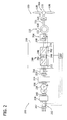
- Fig. 2 is a schematic view of an exemplary electrical and control system 200 that may be used with wind turbine 100.
- Rotor 106 includes blades 108 coupled to hub 110.
- Rotor 106 also includes a low-speed shaft 112 rotatably coupled to hub 110.
- Low-speed shaft 112 is coupled to a step-up gearbox 114 that is configured to step up the rotational speed of low-speed shaft 112 and transfer that speed to a high-speed shaft 116.
- gearbox 114 has a step-up ratio of approximately 70:1.
- low-speed shaft 112 rotating at approximately 20 revolutions per minute (rpm) coupled to gearbox 114 with an approximately 70:1 step-up ratio generates a speed for high-speed shaft 116 of approximately 1400 rpm.
- gearbox 114 has any suitable step-up ratio that facilitates operation of wind turbine 100 as described herein.
- wind turbine 100 includes a direct-drive generator that is rotatably coupled to rotor 106 without any intervening gearbox.
- High-speed shaft 116 is rotatably coupled to generator 118.
- generator 118 is a permanent magnet, three-phase, synchronous generator that includes a generator stator 120 magnetically coupled to a generator rotor 122.
- generator rotor 122 includes a plurality of permanent magnets.
- generator 118 may be an induction (asynchronous) generator.
- Turbine controller 202 includes at least one processor and a memory, at least one processor input channel, at least one processor output channel, and may include at least one computer (none shown in Fig. 2 ).
- the term computer is not limited to integrated circuits referred to in the art as a computer, but broadly refers to a processor, a microcontroller, a microcomputer, a programmable logic controller (PLC), an application specific integrated circuit, and other programmable circuits (none shown in Fig. 2 ), and these terms are used interchangeably herein.
- memory may include, but is not limited to, a computer-readable medium, such as a random access memory (RAM) (none shown in Fig.
- additional input channels may be, but are not limited to, computer peripherals associated with an operator interface such as a mouse and a keyboard (neither shown in Fig. 2 ).
- additional output channels may include, but are not limited to, an operator interface monitor (not shown in Fig. 2 ).
- Processors for turbine controller 202 process information transmitted from a plurality of electrical and electronic devices that may include, but are not limited to, voltage and current transducers.
- RAM and/or storage devices store and transfer information and instructions to be executed by the processor.
- RAM and/or storage devices can also be used to store and provide temporary variables, static (i.e., non-changing) information and instructions, or other intermediate information to the processors during execution of instructions by the processors.
- Instructions that are executed include, but are not limited to, resident conversion and/or comparator algorithms. The execution of sequences of instructions is not limited to any specific combination of hardware circuitry and software instructions.
- Generator stator 120 is electrically coupled to a power conversion assembly 210 via a stator bus 208.
- stator bus 208 transmits three-phase power from generator stator 120 to stator synchronizing switch 206.
- the power conversion assembly 210 is electrically coupled to a main transformer circuit breaker 214 via a system bus 216.
- one or more fuses are used instead of main transformer circuit breaker 214.
- neither fuses nor main transformer circuit breaker 214 is used.
- Power conversion assembly 210 includes a stator-side power converter 220 electrically coupled to the stator bus 208.
- the rotor-side power converter 220 is electrically coupled to a line-side power converter 222.
- Stator-side power converter 220 and line-side power converter 222 are power converter bridges including power semiconductors (not shown).
- stator-side power converter 220 and line-side power converter 222 are configured in a three-phase, pulse width modulation (PWM) configuration including insulated gate bipolar transistor (IGBT) switching devices (not shown in Fig. 2 ) that operate as known in the art.
- PWM pulse width modulation
- IGBT insulated gate bipolar transistor
- stator-side power converter 220 and line-side power converter 222 may have a configuration using any switching devices that facilitates operation of electrical and control system 200 as described herein.
- Power conversion assembly 210 is coupled in electronic data communication with turbine controller 202 to control the operation of stator-side power converter 220 and line-side power converter 222.
- the system bus 116 electrically couples line-side power converter 222 to the main transformer circuit breaker 214.
- line-side power converter 222 is electrically coupled to system bus 216 including any suitable protection scheme (not shown).
- Main transformer circuit breaker 214 is electrically coupled to an electric power main transformer 234 via a generator-side bus 236.
- Main transformer 234 is electrically coupled to a grid circuit breaker 238 via a breaker-side bus 240.
- Grid circuit breaker 238 is connected to the electric power transmission and distribution grid via a grid bus 242.
- main transformer 234 is electrically coupled to one or more fuses (not shown), rather than to grid circuit breaker 238, via breaker-side bus 240.
- neither fuses nor grid circuit breaker 238 is used, but rather main transformer 234 is coupled to the electric power transmission and distribution grid via breaker-side bus 240 and grid bus 242.
- stator-side power converter 220 is coupled in electrical communication with line-side power converter 222 via a single direct current (DC) link 244.
- DC link 244 includes a positive rail 246, a negative rail 248, and at least one capacitor 250 coupled between positive rail 246 and negative rail 248.
- capacitor 250 includes one or more capacitors configured in series and/or in parallel between positive rail 246 and negative rail 248.
- Turbine controller 202 is configured to receive a plurality of voltage and electric current measurement signals from a first set of voltage and electric current sensors 252. Moreover, turbine controller 202 is configured to monitor and control at least some of the operational variables associated with wind turbine 100. In the exemplary embodiment, each of three voltage and electric current sensors 252 are electrically coupled to each one of the three phases of grid bus 242. Alternatively, voltage and electric current sensors 252 are electrically coupled to system bus 216. As a further alternative, voltage and electric current sensors 252 are electrically coupled to any portion of electrical and control system 200 that facilitates operation of electrical and control system 200 as described herein. As a still further alternative, turbine controller 202 is configured to receive any number of voltage and electric current measurement signals from any number of voltage and electric current sensors 252 including, but not limited to, one voltage and electric current measurement signal from one transducer.
- electrical and control system 200 also includes a converter controller 262 that is configured to receive a plurality of voltage and electric current measurement signals.
- converter controller 262 receives voltage and electric current measurement signals from a second set of voltage and electric current sensors 254 coupled in electronic data communication with stator bus 208.
- Converter controller 262 receives a third set of voltage and electric current measurement signals from a third set of voltage and electric current sensors 256 coupled in electronic data communication with system bus 212.
- Converter controller 262 is substantially similar to turbine controller 202 and is coupled in electronic data communication with turbine controller 202.
- converter controller 262 is physically integrated within power conversion assembly 210.
- converter controller 262 has a configuration that facilitates operation of electrical and control system 200 as described herein.
- Low-speed shaft 112 drives gearbox 114 that subsequently steps up the low rotational speed of low-speed shaft 112 to drive high-speed shaft 116 at an increased rotational speed.
- High speed shaft 116 rotatably drives generator rotor 122.
- a rotating magnetic field is induced by generator rotor 122 within generator stator 120.
- Generator 118 converts the rotational mechanical energy to a sinusoidal, three-phase alternating current (AC) electrical energy signal in generator stator 120.
- AC alternating current
- main transformer 234 The associated electrical power is transmitted to main transformer 234 via stator bus 208, the power conversion assembly 210, system bus 216, main transformer circuit breaker 214 and generator-side bus 236.
- Main transformer 234 steps up the voltage amplitude of the electrical power and the transformed electrical power is further transmitted to a grid via breaker-side bus 240, grid circuit breaker 238 and grid bus 242.
- stator-side power converter 220 acts as a rectifier and rectifies the sinusoidal, three-phase AC power to DC power.
- the DC power is transmitted into DC link 244.
- Capacitor 250 facilitates mitigating DC link 244 voltage amplitude variations by facilitating mitigation of a DC ripple associated with AC rectification.
- the DC power is subsequently transmitted from DC link 244 to line-side power converter 222 and line-side power converter 222 acts as an inverter configured to convert the DC electrical power from DC link 244 to three-phase, sinusoidal AC electrical power with pre-determined voltages, currents, and frequencies. This conversion is monitored and controlled via converter controller 262.
- the converted AC power is transmitted from line-side power converter 222 to system bus 216.
- Main transformer circuit breaker 214, and grid circuit breaker 238 are configured to disconnect corresponding buses, for example, when excessive current flow may damage the components of electrical and control system 200. Additional protection components may be also provided.
- Power conversion assembly 210 is configured to receive control signals from turbine controller 202.
- the control signals are based on sensed conditions or operating characteristics of wind turbine 100 and electrical and control system 200.
- the control signals are received by turbine controller 202 and used to control operation of power conversion assembly 210.
- Feedback from one or more sensors may be used by electrical and control system 200 to control power conversion assembly 210 via converter controller 262 including, for example, stator bus voltages, electric current sensors 254, grid bus voltages and electric current sensors 252, and system bus voltages and the respective electric current sensors 256.
- switching control signals, stator synchronizing switch control signals and system circuit breaker control (trip) signals may be generated in any known manner.
- the power conversion assembly 210 may operate in a specific input voltage range that may be converted by the stator side power converter 220 may be between 200 and 5000V, in particular between 500 and 1000V.
- Fig. 3 shows schematic drawing of an embodiment of a three phase generator 300.
- the generator may be a permanent magnet generator, an electrically excited synchronous generator or an asynchronous generator.
- the generator 300 includes a rotor 310 and a stator 320.
- the rotor 310 is mechanically connected to the wind rotor 106, in a typical embodiment via a gear box.
- the rotor 310 includes at least two permanent magnets 312, 314 wherein the north poles 314 and south poles 312 are alternately arranged on the circumference of the rotor 310.
- the rotor 310 may include more than two permanent magnets.
- the generator may include excitation coils for increasing or reducing the magnetic field of the permanent magnets 312, 314.
- the stator includes three coils 322, 325, 328, wherein each phase of a three phase current is connected to a respective winding.
- the generator 300 may include more coils, for example two or more coils for each phase.
- a voltage is induced in the coils 322, 325, 328 of the stator.
- the induced voltage is proportional to the rotational speed of a rotor of the generator.
- the coils 322, 325, 328 of the stator may be, for example, connected to a circuit breaker, a commutator, or an inverter, as shown in Fig. 2 .
- each coil 322, 325, 328 may include at least two subcoils 323, 324, 326, 327, 328, 329 respectively.
- the subcoils 323, 324, 326, 327, 328, 329 of the respective coils 322, 325, 328 may be connected in series and in parallel.
- the subcoils of each coil are arranged coaxially, in particular one after the other, so that they are disposed with respect to the rotating axis of the rotor at a different radial distance.
- the subcoils of each coil are arranged on a respective same radius 332, 333, 334.
- the form and the placement of the coils may be adapted such that substantially the same voltage is induced in each subcoil of the stator by the magnetic field of the rotor.
- the diameter of the coil may vary from one subcoil to another subcoil of the same coil.
- the rotor of the generator may be disposed outside the stator.
- the arrangement of the stator and the rotor may depend, for example, on the type of the wind turbine and/or the size of the nacelle.
- Fig. 4 shows a schematically electrical circuit of a generator according to an embodiment.
- the electrical circuit includes three coils 422, 425, 428, wherein each coil 422, 425, 428 includes two subcoils 423, 424, 426, 427, 428, 429.
- the coils are connected with three phases L1, L2, L3 in a delta connection.
- the coils 422, 425, 428 may be connected in a star connection to the three phases L1, L2, L3.
- a generator may switch the coils 422, 425, 428 from a star connection to a delta connection and vice versa, in particular depending on the operation conditions of the wind turbine.
- Fig. 4 shows a schematically electrical circuit of a generator according to an embodiment.
- the electrical circuit includes three coils 422, 425, 428, wherein each coil 422, 425, 428 includes two subcoils 423, 424, 426, 427, 428, 429.
- the coils are connected with three phases L1, L2,
- the subcoils are connected in series, such that the two subcoils 423, 424, 426, 427, 428, 429 of each coil 422, 425, 428 form a common coil.
- the turns of each subcoil 423, 424, 426, 427, 428, 429 of each coil have the same direction for each radial axis of the coils.
- Fig. 5 the same electrical circuit is shown as in Fig. 5 , but with a parallel connection of the subcoils of each coil 422, 425, 428.
- the subcoils 423, 424, 426, 427, 428, 429 of a coil may be switched in parallel or in series depending on the conditions or the condition in which the wind turbine is operated.
- each coil 422, 425, 428 includes at least one switch 431, 433, 435, 437, 439, 441.
- the switching time may be between 1 and 10 seconds, for example between 2 and 5 seconds.
- the subcoils 323, 324, 326, 327, 328, 329, 423, 424, 426, 427, 428, 429 of each coil are respectively connected in parallel, such that a high current with a relative low voltage may be produced.
- the subcoils 323, 324, 326, 327, 328, 329, 423, 424, 426, 427, 428, 429 are connected in series, such that a low current with a high voltage is produced.
- the useable range of rotational speeds in which the wind turbine can be operated is increased, by using a serial connection in low rotational speeds of the rotor 106 of the wind turbine 100 and a parallel connection of the subcoils for each coil at high rotational speeds of the wind turbine.
- the inverter of a wind turbine may be only operated between 500 and 1000 volts.
- the subcoils switched in parallel may be changed to a serial configuration, such that the output voltage is increased.
- Fig. 6 and Fig. 7 show a section of a further embodiment of a schematical electrical circuit of a permanent magnet generator 500.
- the generator 500 includes a generator stator 502, and a generator rotor 504, wherein the permanent magnets 506, 508 are regularly placed around the circumference of the generator rotor. In particular towards the generator stator 502 the south and north poles of the magnets 506, 508 are disposed alternately.
- the generator stator 502 includes a plurality of coils 510, 520, 530, 540 each having two subcoils 512, 514, 522, 524, 532, 534, 542, 544, namely a radial inner subcoil 512, 522, 532, 542 and a radial outer subcoil 514, 524, 534, 544.
- Figs. 6 and 7 the coils of only one phase are shown.
- the coils of further phases would be placed respectively between two adjacent coils 510, 520, 530, 540.
- the radial inner subcoils 512, 522, 532, 542 may form a first group of coils 560 and the radial outer subcoils may form a second group of coils 570.
- the permanent magnet generator 500 of Figs. 6 and 7 may have two different states. In a first state, shown in Fig. 6 , all coils 510, 520, 530, 540 are electrically connected in series. Further, the subcoils 512, 514, 522, 524, 532, 534, 542, 544 of each coil 510, 520, 530, 540 are electrically connected in series. In a second state shown in Fig. 7 , the inner subcoils 512, 522, 532, 542 are connected in series to form a system of inner subcoils and the outer subcoils 514, 524, 534, 544 are connected in series to form a system of outer subcoils.
- the system of inner subcoils and the system of outer subcoils are electrically connected in parallel.
- the subcoils 512, 514, 522, 524, 532, 534, 542, 544 or coils 510, 520, 530, 540 of one phase are disposed such that substantially the same voltage is induced into the coils by the magnets 506, 508 of the generator rotor 504. If the rotor is rotating with the same speed in the first and the second state, the voltage U AB between the points A and B of the electric circuit in the first state is higher than the voltage U AB between the points A and B of the electric circuit in the second state.
- first group of coils 560 is connected in parallel to the second group of coils 570.
- Fig. 8 to Fig. 10 show a section of a further embodiment of a schematical electrical circuit of a permanent magnet generator 600.
- the generator 600 includes a generator stator 602 and a generator rotor 604, wherein the permanent magnets 606, 608 are regularly placed around the circumference of the generator rotor. In particular towards the generator stator 602, the south and north poles of the magnets 606, 608 are disposed alternately.
- the generator stator 602 includes a plurality of coils 610, 620, 630, 640. In Figs. 8 to 10 the coils of only one phase are shown. The coils of further phases would be placed respectively between two adjacent coils 610, 620, 630, 640. Typically, the coils 610, 620, 630, 640 of one phase are disposed such that substantially the same voltage is induced into the coils by the magnets 606, 608 of the generator rotor 604.
- the permanent magnet generator 500 of Figs. 8 to 10 may have three different states. In a first state, shown in Fig. 8 , all coils 510, 520, 530, 540 are electrically connected in series. In a second and a third state shown in Figs 9 and 10 the coils are separated in a first group of coils and a second group of coils, each group of coils includes the half of the coils of the respective phase. The coils within each group of coils are electrically connected in series, and the first and the second group of coils are electrically connected in parallel. In Fig.
- a first group of coils includes every second coil 610, 630 in a circumferential direction of the same phase, and a second group of coils includes the remaining coils 620, 640 of the same phase.
- the first group of coils may include half of the coils of a phase, wherein the coils are disposed adjacent to each other - for example the coils of one phase disposed on a first half of a circumference of the stator - and the second group of coils may include the remaining half of coils of the phase - for example the coils of the phase disposed on a second half of the circumference of the stator.
- the voltage U AB between the points A and B of the electric circuit in the first state is higher than the voltage U AB between the points A and B of the electric circuit in the second state and the third state.
- the voltage U AB in the first state would be twice the voltage U AB in the second and the third state.
- Figs. 6 to 10 only four coils of a phase are shown for the sake of simplicity, but the electrical connections between the coils of the first, second and third state of the permanent magnet generator may be also realized with more coils. Also more than two groups of coils or subcoils may be provided for realizing more possibilities to adapt to output voltage of the permanent magnet generator.
- a method is disclosed wherein the windings of a generator, in particular a permanent magnet generator, are switched to step up the output voltage level from parallel to series.
- the idea is to connect a contactor into the generator system in such a way that the windings may be switched in parallel or series. This may enlarge the usable operating range of the speed variable generator system. If the windings are switched in series the output voltage of the generator will be doubled, in particular in case of subcoils having the same amount of turns.
- the speed range of a wind turbine may be enlarged into a lower speed range, such that it may optimize the power coefficient (Cp) factor of the wind turbine.
- the converter of the wind turbine may stay longer productive into low speed areas.
- Fig. 11 a flowchart of a method is shown.
- the rotational speed of the rotor of the generator is determined (Box 1000), such that the output voltage of the generator in different states of the generator may be estimated (Box 1010).
- the different states include for example different connections of the coils and/or subcoils of the generator, for example the states shown in the embodiments of Figs 6 to 10 .
- the calculated output voltage of the different states is compared with at least one predetermined voltage range, which may be for example the upper and lower end of the operating range of the power converter of the wind turbine (Box 1020). If the generator may be operated in at least one state such that the output voltage is within the predetermined voltage range, the generator is operated in that state (Box 1030). Then, the process may start again at Box 1000. Also other voltages may be used as reference threshold voltages or voltage ranges, for example a minimum voltage to be fed into the grid.
- substantially the same voltage is induced in each coil of the same phase.
- the method according to an embodiment disclosed herein may include determining the generator speed.
- a method according to an embodiment may include generating a signal for changing the state of the generator if a rotational speed of the generator rotor exceeds or goes below a predetermined threshold rotational speed.
- a method may include generating the signal for changing the state if a reference voltage exceeds or goes below a predetermined threshold voltage, wherein the reference voltage is selected from at least one voltage selected from a group consisting of a voltage of a coil, a voltage of a group of coils, a voltage of a subgroup, and a magnet wheel voltage.
- the voltage of a coil, of a group of coils, of subgroup of coils is the voltage that can be measured between the two ends of coil, the group of coils or the subgroup of coils
- the threshold voltage depends on at least one voltage selected of the group consisting of a minimum input voltage of a converter of the wind turbine, a maximum input voltage of the converter of the wind turbine, minimum output voltage of the converter of the wind turbine, a maximum output voltage of the converter of the wind turbine, a minimum input voltage of a power electronic device, a maximum input voltage of the power electronic device, a minimum output voltage of the power electronic device, and a maximum output voltage of the power electronic device.
- the power electronic device is disposed in the electric system of the wind turbine, in particular three phase electric system of the wind turbine. Typically, portions of the electric system of the wind turbine may be placed in a separate control cabinet outside the tower of the wind turbine.
- the generator is a permanent magnet generator.
- the generator is a three-phase generator.
- the coils of the subgroups have substantially the same number of turns.
- the coils of the subgroups have substantially the same number of turns.
- the coil arrangement is disposed in a stator of an electrical machine.
- the electrical machine is a permanent magnet three-phase machine.
- the axes of the coils of the respective subgroups are disposed on the same radius of the electrical machine.
- electrical machine as a rotational axis, around which the generator rotor rotates.
- the radius of the electrical machine extends radially from the rotational axis of the electrical machine.
- the controller is adapted to generate a signal for changing the state of the generator if the rotational speed of the generator rotor exceeds or goes below a predetermined threshold rotational speed.
- the controller is adapted to generate a signal for changing the state if a reference voltage exceeds or goes below a predetermined threshold voltage, wherein the reference voltage is selected from at least one voltage selected from a group consisting of a voltage of a coil, a voltage of a group of coils, a voltage of a subgroup, and a magnet wheel voltage.
Landscapes
- Engineering & Computer Science (AREA)
- Power Engineering (AREA)
- Control Of Eletrric Generators (AREA)
- Wind Motors (AREA)
Applications Claiming Priority (1)
| Application Number | Priority Date | Filing Date | Title |
|---|---|---|---|
| US12/826,023 US8039982B2 (en) | 2010-06-29 | 2010-06-29 | Method for operating a wind turbine, coil arrangement for an electric machine, and controller for a wind turbine |
Publications (2)
| Publication Number | Publication Date |
|---|---|
| EP2400656A2 true EP2400656A2 (fr) | 2011-12-28 |
| EP2400656A3 EP2400656A3 (fr) | 2018-03-28 |
Family
ID=44142067
Family Applications (1)
| Application Number | Title | Priority Date | Filing Date |
|---|---|---|---|
| EP11170664.4A Withdrawn EP2400656A3 (fr) | 2010-06-29 | 2011-06-21 | Procédé de fonctionnement d'une éolienne, agencement de bobine pour machine électrique et contrôleur pour éolienne |
Country Status (3)
| Country | Link |
|---|---|
| US (1) | US8039982B2 (fr) |
| EP (1) | EP2400656A3 (fr) |
| CN (1) | CN102368644A (fr) |
Cited By (4)
| Publication number | Priority date | Publication date | Assignee | Title |
|---|---|---|---|---|
| GB2491008A (en) * | 2011-05-10 | 2012-11-21 | Boeing Co | Generator with reconfigurable stator |
| US20190013759A1 (en) | 2014-08-01 | 2019-01-10 | Falcon Power, LLC | Variable torque motor/generator/transmission |
| EP3443662A4 (fr) * | 2016-04-13 | 2019-12-25 | Falcon Power LLC | Moteur/génératrice/transmission à couple variable |
| US11296638B2 (en) | 2014-08-01 | 2022-04-05 | Falcon Power, LLC | Variable torque motor/generator/transmission |
Families Citing this family (27)
| Publication number | Priority date | Publication date | Assignee | Title |
|---|---|---|---|---|
| CN102160277A (zh) * | 2008-09-03 | 2011-08-17 | Exro技术公司 | 用于多级发生器的功率转换系统 |
| EP2498381B1 (fr) * | 2011-03-08 | 2018-10-10 | Siemens Aktiengesellschaft | Segment de bobine de stator pour transducteur électro-mécanique, en particulier un générateur et transducteur électro-mécanique, en particulier un générateur électrique |
| GB201110719D0 (en) * | 2011-06-24 | 2011-08-10 | Rolls Royce Plc | Electrical system architecture and electrical power generation system |
| WO2013175252A1 (fr) * | 2012-05-24 | 2013-11-28 | Elis Mantovani | Dispositif générateur cinétique d'électricité |
| CN102904402B (zh) * | 2012-10-22 | 2016-12-21 | 王秋安 | 一种多方式输出的风力发电机 |
| EP2733824A1 (fr) * | 2012-11-16 | 2014-05-21 | Siemens Aktiengesellschaft | Stator pour machine électrique |
| JP5549751B1 (ja) * | 2013-01-31 | 2014-07-16 | 株式会社安川電機 | インバータ装置、インバータ装置の制御方法、及び電動機ドライブシステム |
| JP5569606B1 (ja) * | 2013-02-01 | 2014-08-13 | 株式会社安川電機 | インバータ装置および電動機ドライブシステム |
| US9871427B2 (en) | 2013-03-15 | 2018-01-16 | Ingersoll-Rand Company | Stator winding for an electric motor |
| ES2703542T3 (es) * | 2013-09-05 | 2019-03-11 | Vestas Wind Sys As | Gestión de velocidad de una turbina eólica cuando se conmutan configuraciones eléctricas |
| FR3016755B1 (fr) * | 2014-01-17 | 2017-11-24 | Save Ingenierie | Procede de gestion d'une machine electromagnetique permettant la modification de la topologie d'un circuit d'induits de ladite machine |
| DE102014222163A1 (de) * | 2014-07-25 | 2016-01-28 | Robert Bosch Gmbh | Elektrische Maschine zur Energieversorgung eines Kraftfahrzeugbordnetzes |
| US10054108B2 (en) * | 2014-10-10 | 2018-08-21 | General Electric Company | Wind turbine system and method for controlling a wind turbine system by power monitoring |
| US10075114B2 (en) * | 2016-03-03 | 2018-09-11 | General Electric Company | System and method for controlling DC link voltage of a power converter |
| US10340829B2 (en) * | 2016-07-25 | 2019-07-02 | General Electric Company | Electrical power circuit and method of operating same |
| CN110168866A (zh) * | 2016-11-09 | 2019-08-23 | Tvs电机股份有限公司 | 具有多区段绕组线圈和开关组合的定子的电机 |
| US10541634B2 (en) * | 2017-03-17 | 2020-01-21 | Hamilton Sundstrand Corporation | Generator arrangements and methods of controlling generator arrangements |
| CN108933500B (zh) * | 2017-05-23 | 2020-06-02 | 东洋合成股份有限公司 | 可低转速高电能的风力发电装置 |
| DE102018102122A1 (de) * | 2018-01-31 | 2019-08-01 | Tdk Electronics Ag | Maschinen mit leistungselektronischen Energiewandlern und Ableitstromkompensation und Anlage |
| EP3890181A1 (fr) * | 2020-04-03 | 2021-10-06 | ABB Schweiz AG | Procédé de fonctionnement d'un générateur à phases multiples et agencement pour générateur à phases multiples |
| US11486360B2 (en) | 2020-04-10 | 2022-11-01 | General Electric Company | System and method for controlling wind turbine converters during high voltage ride through events |
| CN111555508B (zh) * | 2020-05-27 | 2021-11-30 | 北京亿马先锋汽车科技有限公司 | 切换电机绕组抽头的连接方式的方法及装置 |
| CN112145347B (zh) * | 2020-09-03 | 2022-07-01 | 上海电气风电集团股份有限公司 | 风力发电系统及其控制方法和装置 |
| CN112332724B (zh) * | 2020-11-13 | 2022-02-11 | 中国科学院电工研究所 | 发电机、发电系统及发电机控制方法 |
| DE102021204292A1 (de) * | 2021-04-29 | 2022-11-03 | Rolls-Royce Deutschland Ltd & Co Kg | Ständer für eine elektrische Maschine |
| AT526546B1 (de) * | 2022-10-13 | 2025-08-15 | Avl List Gmbh | Elektromotor |
| EP4447307A1 (fr) * | 2023-04-13 | 2024-10-16 | Tero Arpiainen | Système et procédé de commande de générateur d'éolienne |
Citations (3)
| Publication number | Priority date | Publication date | Assignee | Title |
|---|---|---|---|---|
| US3381154A (en) * | 1964-04-08 | 1968-04-30 | Asea Ab | High power synchronous machine |
| JP2004328917A (ja) * | 2003-04-25 | 2004-11-18 | Nissan Motor Co Ltd | 同期電動機 |
| US20100133816A1 (en) * | 2009-06-30 | 2010-06-03 | Mehdi Abolhassani | Power Converter For Use With Wind Generator |
Family Cites Families (6)
| Publication number | Priority date | Publication date | Assignee | Title |
|---|---|---|---|---|
| CN1269288C (zh) * | 2003-06-25 | 2006-08-09 | 原泽 | 适应转速大范围变化的分点全压发电方法 |
| US7116080B2 (en) * | 2004-07-07 | 2006-10-03 | Visteon Global Technologies, Inc. | Alternator rectifier with coil-sensor controlled MOSFETs |
| US7348764B2 (en) * | 2006-07-13 | 2008-03-25 | Ocean Power Technologies, Inc. | Coil switching of an electric generator |
| US7977842B2 (en) * | 2006-10-05 | 2011-07-12 | Lin Panchien | Adaptive winding system and control method for electric machines |
| US7656135B2 (en) * | 2007-01-05 | 2010-02-02 | General Electric Company | Method and apparatus for controlling rotary machines |
| CN101183847B (zh) * | 2007-09-24 | 2011-05-18 | 南京航空航天大学 | 多体式电励磁双凸极风力发电机 |
-
2010
- 2010-06-29 US US12/826,023 patent/US8039982B2/en not_active Expired - Fee Related
-
2011
- 2011-06-21 EP EP11170664.4A patent/EP2400656A3/fr not_active Withdrawn
- 2011-06-29 CN CN2011101914340A patent/CN102368644A/zh active Pending
Patent Citations (3)
| Publication number | Priority date | Publication date | Assignee | Title |
|---|---|---|---|---|
| US3381154A (en) * | 1964-04-08 | 1968-04-30 | Asea Ab | High power synchronous machine |
| JP2004328917A (ja) * | 2003-04-25 | 2004-11-18 | Nissan Motor Co Ltd | 同期電動機 |
| US20100133816A1 (en) * | 2009-06-30 | 2010-06-03 | Mehdi Abolhassani | Power Converter For Use With Wind Generator |
Cited By (15)
| Publication number | Priority date | Publication date | Assignee | Title |
|---|---|---|---|---|
| GB2491008A (en) * | 2011-05-10 | 2012-11-21 | Boeing Co | Generator with reconfigurable stator |
| US8803384B2 (en) | 2011-05-10 | 2014-08-12 | The Boeing Company | Stators with reconfigurable coil paths |
| GB2491008B (en) * | 2011-05-10 | 2014-09-17 | Boeing Co | Reconfigurable stators |
| US10879828B2 (en) | 2014-08-01 | 2020-12-29 | Falcon Power, LLC | Variable torque motor/generator/transmission |
| US20190068102A1 (en) | 2014-08-01 | 2019-02-28 | Falcon Power, LLC | Variable torque motor/generator/transmission |
| US20190013759A1 (en) | 2014-08-01 | 2019-01-10 | Falcon Power, LLC | Variable torque motor/generator/transmission |
| US10892700B2 (en) | 2014-08-01 | 2021-01-12 | Falcon Power, LLC | Variable torque motor/generator/transmission |
| US11296638B2 (en) | 2014-08-01 | 2022-04-05 | Falcon Power, LLC | Variable torque motor/generator/transmission |
| US11362611B2 (en) | 2014-08-01 | 2022-06-14 | Falcon Power, LLC | Variable torque motor/generator/transmission |
| US11695364B2 (en) | 2014-08-01 | 2023-07-04 | Falcon Power, LLC | Variable torque motor/generator/transmission |
| US11888421B2 (en) | 2014-08-01 | 2024-01-30 | Falcon Power, LLC | Variable torque motor/generator/transmission |
| US12438488B2 (en) | 2014-08-01 | 2025-10-07 | Falcon Power, LLC | Variable torque motor/generator/transmission |
| US12567823B2 (en) | 2014-08-01 | 2026-03-03 | Falcon Power, LLC | Variable torque motor/generator/transmission |
| EP3443662A4 (fr) * | 2016-04-13 | 2019-12-25 | Falcon Power LLC | Moteur/génératrice/transmission à couple variable |
| EP3934093A1 (fr) * | 2016-04-13 | 2022-01-05 | Falcon Power LLC | Moteur/générateur/transmission à couple variable |
Also Published As
| Publication number | Publication date |
|---|---|
| EP2400656A3 (fr) | 2018-03-28 |
| CN102368644A (zh) | 2012-03-07 |
| US20110140421A1 (en) | 2011-06-16 |
| US8039982B2 (en) | 2011-10-18 |
Similar Documents
| Publication | Publication Date | Title |
|---|---|---|
| US8039982B2 (en) | Method for operating a wind turbine, coil arrangement for an electric machine, and controller for a wind turbine | |
| US7843078B2 (en) | Method and apparatus for generating power in a wind turbine | |
| US8519568B2 (en) | Inrush current protection for wind turbines and wind farms | |
| EP2333320B1 (fr) | Procédé et appareil pour contrôler une éolienne | |
| JP6008473B2 (ja) | 発電機およびその製造方法 | |
| US20130147201A1 (en) | Contactless power transfer device and method | |
| EP3096005A1 (fr) | Limite de schéma de dépréciation utilisé dans une commande de turbine éolienne | |
| US9088150B2 (en) | Overvoltage clipping device for a wind turbine and method | |
| US6943462B2 (en) | Ring generator for a wind power installation | |
| US8451573B1 (en) | Overvoltage protection device for a wind turbine and method | |
| CN110603707B (zh) | 电功率系统和子系统 | |
| EP3410555B1 (fr) | Systèmes d'alimentation électrique ayant des transformateurs en zigzag | |
| EP3204637B1 (fr) | Système de turbine éolienne et procédé de commande d'un système de turbine éolienne par contrôle de l'énergie | |
| US20130301167A1 (en) | Transformer arrangement for wind turbine and method for controlling voltage | |
| US9494139B2 (en) | System and method for controlling a power output of a wind turbine generator | |
| US10218298B2 (en) | Spillover of reactive current to line side converter | |
| US10288040B2 (en) | Current limit calculation for wind turbine control | |
| US11959464B2 (en) | Wind turbine generators and methods for rotating a hub of a wind turbine | |
| Wang et al. | Design and performance of large scale direct-driven permanent magnet wind generators |
Legal Events
| Date | Code | Title | Description |
|---|---|---|---|
| AK | Designated contracting states |
Kind code of ref document: A2 Designated state(s): AL AT BE BG CH CY CZ DE DK EE ES FI FR GB GR HR HU IE IS IT LI LT LU LV MC MK MT NL NO PL PT RO RS SE SI SK SM TR |
|
| AX | Request for extension of the european patent |
Extension state: BA ME |
|
| PUAI | Public reference made under article 153(3) epc to a published international application that has entered the european phase |
Free format text: ORIGINAL CODE: 0009012 |
|
| PUAL | Search report despatched |
Free format text: ORIGINAL CODE: 0009013 |
|
| AK | Designated contracting states |
Kind code of ref document: A3 Designated state(s): AL AT BE BG CH CY CZ DE DK EE ES FI FR GB GR HR HU IE IS IT LI LT LU LV MC MK MT NL NO PL PT RO RS SE SI SK SM TR |
|
| AX | Request for extension of the european patent |
Extension state: BA ME |
|
| RIC1 | Information provided on ipc code assigned before grant |
Ipc: H02P 25/18 20060101AFI20180217BHEP Ipc: H02P 9/02 20060101ALI20180217BHEP |
|
| STAA | Information on the status of an ep patent application or granted ep patent |
Free format text: STATUS: REQUEST FOR EXAMINATION WAS MADE |
|
| 17P | Request for examination filed |
Effective date: 20180928 |
|
| RBV | Designated contracting states (corrected) |
Designated state(s): AL AT BE BG CH CY CZ DE DK EE ES FI FR GB GR HR HU IE IS IT LI LT LU LV MC MK MT NL NO PL PT RO RS SE SI SK SM TR |
|
| STAA | Information on the status of an ep patent application or granted ep patent |
Free format text: STATUS: EXAMINATION IS IN PROGRESS |
|
| 17Q | First examination report despatched |
Effective date: 20190111 |
|
| STAA | Information on the status of an ep patent application or granted ep patent |
Free format text: STATUS: THE APPLICATION HAS BEEN WITHDRAWN |
|
| 18W | Application withdrawn |
Effective date: 20210217 |