EP2400663A1 - Circuit d'alimentation électrique en CA - Google Patents
Circuit d'alimentation électrique en CA Download PDFInfo
- Publication number
- EP2400663A1 EP2400663A1 EP10166270A EP10166270A EP2400663A1 EP 2400663 A1 EP2400663 A1 EP 2400663A1 EP 10166270 A EP10166270 A EP 10166270A EP 10166270 A EP10166270 A EP 10166270A EP 2400663 A1 EP2400663 A1 EP 2400663A1
- Authority
- EP
- European Patent Office
- Prior art keywords
- power
- switching
- circuitry according
- power line
- communications data
- Prior art date
- Legal status (The legal status is an assumption and is not a legal conclusion. Google has not performed a legal analysis and makes no representation as to the accuracy of the status listed.)
- Withdrawn
Links
- 238000004891 communication Methods 0.000 claims abstract description 47
- 239000004065 semiconductor Substances 0.000 claims abstract description 35
- 230000008878 coupling Effects 0.000 claims abstract description 13
- 238000010168 coupling process Methods 0.000 claims abstract description 13
- 238000005859 coupling reaction Methods 0.000 claims abstract description 13
- 238000000605 extraction Methods 0.000 claims description 7
- 239000012530 fluid Substances 0.000 claims description 5
- 238000012544 monitoring process Methods 0.000 claims description 4
- 230000001419 dependent effect Effects 0.000 claims 3
- 239000007787 solid Substances 0.000 description 10
- 230000005540 biological transmission Effects 0.000 description 4
- 230000000903 blocking effect Effects 0.000 description 2
- 230000003111 delayed effect Effects 0.000 description 2
- 238000000034 method Methods 0.000 description 2
- 238000010586 diagram Methods 0.000 description 1
- 239000000284 extract Substances 0.000 description 1
- 238000005070 sampling Methods 0.000 description 1
- 230000001360 synchronised effect Effects 0.000 description 1
- 238000011144 upstream manufacturing Methods 0.000 description 1
Images
Classifications
-
- H—ELECTRICITY
- H04—ELECTRIC COMMUNICATION TECHNIQUE
- H04B—TRANSMISSION
- H04B3/00—Line transmission systems
- H04B3/54—Systems for transmission via power distribution lines
-
- H—ELECTRICITY
- H04—ELECTRIC COMMUNICATION TECHNIQUE
- H04B—TRANSMISSION
- H04B2203/00—Indexing scheme relating to line transmission systems
- H04B2203/54—Aspects of powerline communications not already covered by H04B3/54 and its subgroups
- H04B2203/5404—Methods of transmitting or receiving signals via power distribution lines
- H04B2203/5412—Methods of transmitting or receiving signals via power distribution lines by modofying wave form of the power source
Definitions
- the present invention relates to AC power supply circuitry.
- AC power control using solid state circuitry is typically provided by the employment of solid state semiconductor based power switching devices such as triacs, back-to-back thyristors and insulated-gate bipolar transistors (IGBTs). Control is achieved by delaying the switching on of the device at each half cycle of the AC supply, so that only part of the AC supply waveform is applied to a load.
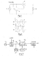
- the electrical pulses to the trigger electrode of the triac or thyristor or the gate of an IGBT are delayed by simple electronic circuitry, with a variable delay to provide variable power control. This is illustrated in Fig. 1 , for a power controller feeding a simple resistive load.
- the circuit consists of an AC power source 1, which is connected via a solid state semiconductor based power switching device 2, in this case a triac, in an AC power line to a load 3.
- a variable delay to each trigger pulse from a control input to the triac 2 is provided by a simple electronic module 4.
- Fig. 2 shows the AC voltage waveform 5 of the power source 1 and the electrical trigger pulses 6 applied to the trigger electrode of the triac 2, each delayed in time from the zero crossing point of the voltage waveform 5 and generated by the electronic module 4, resulting in the truncated sine wave voltage waveform 7 across the load 3.
- triacs, thyristors and IGBTs are simply used as switches, but even in these applications such a device cannot be switched on until the voltage waveform across it has risen by a few volts, so there are periods of time when the power supply is effectively disconnected from the load, even though they are shorter than in the case of devices used for variable AC power control.
- the power line is also used as a data communication line by the coupling of communications data on to the AC power line, such a system being known as a communication on power (COP) system.
- COP communication on power
- the "off periods" of a solid state semiconductor based power switching device result in corruption of the communications data. Consequently, current COP systems remove the communications data from the power line, upstream of the power switching device, and reintroduce the communications data to the power line downstream of the power switching device, at considerable expense, particularly if the power line is very high voltage.
- This invention overcomes the need to remove and reintroduce communications data in a COP system using a solid state semiconductor based power switching device.
- AC power supply circuitry comprising:
- said causing means is arranged for monitoring power at said output for determining whether said semiconductor device is in said first state for controlling said coupling means.
- the circuitry is for controlling power supplied to a load, said switching means being arranged for switching said semiconductor device alternately between said first and second states, the periods in which said semiconductor device is in said first and second states typically being variable.
- Said switching means and said semiconductor device are typically such that said device is switched between said first and second states by an electrical pulse from said switching means.
- said switching means typically provides a train of electrical pulses for switching said semiconductor device between said states.
- said semiconductor switching device is in said power line between said coupling means and said source.
- Circuitry according to the invention could include means for receiving power and communications data from said power line, extracting received communications data and passing supplied power to a load.
- receiving means could be connected for receiving power and communications data from such a further switching device.
- Circuitry according to the invention could comprise a power and communications supply in a subsea fluid extraction well complex.
- said source, the first-mentioned switching device and said coupling means are located in topside equipment.
- such a further semiconductor based switching device could be located subsea.
- a COP system with variable control of a semiconductor based power switching device in an AC power line corruption of communications data or failure of such data to propagate through the device is avoided by ensuring that communication is only attempted (i.e. by coupling communications data on to the power line) during periods within the power cycle when the power switching device conduction status supports the propagation of communications data. Transmission of communications data by coupling such data on to the AC power line is therefore synchronised with the AC power waveform.
- Fig. 3 illustrates, diagrammatically, an embodiment of the invention.
- the power source 1 feeds a power line 8 including a solid state control module 9, consisting of a semiconductor based switching device and trigger control circuitry, e.g. as items 2 and 4 of Fig. 1 .
- An electronic monitoring module 10 monitors, by continuous sampling or otherwise, the AC power line voltage and current at the output from module 9 and creates windows for communication during positive and negative half cycles when the switching device in module 9 is switched on to a state where it transmits power to the output.
- the output from the module 10 is a "gating" signal that connects to a modem 11, which under the control of this gating signal, only couples communications data on to the power line after module 9 during such power conduction windows.
- Communications data from modem 11 is coupled on to the power line 8 via a diplexer (DIP) 12, the diplexer including a communications power line coupler (CPLC) 13 and a communications blocking filter (CBF) 14 for preventing communications data from being fed back towards source 1.
- the COP data from diplexer 12 is typically applied for use via an in-line solid state semiconductor based power switch 15.
- communication transmissions are restricted to "burst" operations during the states when the switching device in module 9 is switched on, i.e. within the positive and negative power conduction cycles. This technique therefore avoids trying to propagate communications data through a subsequent, downstream semiconductor based power switching device, during zero voltage and current crossings or during partial conduction states, which can result in transmission failure or data corruption.
- power switch 15 can be a simple solid state switch without the need to remove communications data from COP data before the switch and reintroduce that data on to the power line after the switch.
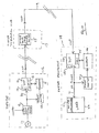
- FIG. 4 this shows, in block diagrammatic form, a power supply and communications system of a subsea fluid extraction well complex.
- topside equipment 16 there are items 1, 8, 9, 10, 11, 12, 13 and 14 of circuitry according to Fig. 3 , the COP data from DIP 12 being sent down an umbilical to a subsea distribution hub 17 in which there is an in-line solid side state semiconductor based power switch 15.
- a subsea distribution hub 17 in which there is an in-line solid side state semiconductor based power switch 15.
- switch 15 switches COP data to subsea equipment 18 via a connection 19, typically there being a long offset distance between hub 17 and equipment 18.
- a diplexer 20 which receives the COP data and which passes AC power on a line 21 to a load 22 which typically could include AC to DC converters 23.
- the extraction of communications data from the COP data input to diplexer 20 is achieved by a modem 24, which extracts communications data from diplexer 20 via its communications power line coupler 25 (this occurring only during the positive and negative half cycles of the power on line 21).
- the diplexer 20 also comprises a communications blocking filter 26 to prevent communications data being passed to line 21. Under the control of an AC power monitoring and synchronization module 27, modem 24 can send communications data up to the topside equipment for extraction by modem 11, module 27 causing synchronization of the transmission of such data to the positive and negative half cycles of the power on line 21.
Landscapes
- Engineering & Computer Science (AREA)
- Power Engineering (AREA)
- Computer Networks & Wireless Communication (AREA)
- Signal Processing (AREA)
- Cable Transmission Systems, Equalization Of Radio And Reduction Of Echo (AREA)
- Remote Monitoring And Control Of Power-Distribution Networks (AREA)
- Stand-By Power Supply Arrangements (AREA)
Priority Applications (7)
| Application Number | Priority Date | Filing Date | Title |
|---|---|---|---|
| EP10166270A EP2400663A1 (fr) | 2010-06-17 | 2010-06-17 | Circuit d'alimentation électrique en CA |
| US13/116,483 US20110309917A1 (en) | 2010-06-17 | 2011-05-26 | Ac power supply circuitry |
| AU2011202689A AU2011202689B2 (en) | 2010-06-17 | 2011-06-06 | AC power supply circuitry |
| BRPI1102870-0A BRPI1102870A2 (pt) | 2010-06-17 | 2011-06-09 | conjunto de circuitos de fornecimento de energia ca |
| SG2011042090A SG177083A1 (en) | 2010-06-17 | 2011-06-09 | Ac power supply circuitry |
| MYPI2011002697A MY155052A (en) | 2010-06-17 | 2011-06-13 | Ac power supply circuitry |
| CN201110175593.1A CN102332938B (zh) | 2010-06-17 | 2011-06-17 | Ac供电电路 |
Applications Claiming Priority (1)
| Application Number | Priority Date | Filing Date | Title |
|---|---|---|---|
| EP10166270A EP2400663A1 (fr) | 2010-06-17 | 2010-06-17 | Circuit d'alimentation électrique en CA |
Publications (1)
| Publication Number | Publication Date |
|---|---|
| EP2400663A1 true EP2400663A1 (fr) | 2011-12-28 |
Family
ID=42635278
Family Applications (1)
| Application Number | Title | Priority Date | Filing Date |
|---|---|---|---|
| EP10166270A Withdrawn EP2400663A1 (fr) | 2010-06-17 | 2010-06-17 | Circuit d'alimentation électrique en CA |
Country Status (7)
| Country | Link |
|---|---|
| US (1) | US20110309917A1 (fr) |
| EP (1) | EP2400663A1 (fr) |
| CN (1) | CN102332938B (fr) |
| AU (1) | AU2011202689B2 (fr) |
| BR (1) | BRPI1102870A2 (fr) |
| MY (1) | MY155052A (fr) |
| SG (1) | SG177083A1 (fr) |
Cited By (1)
| Publication number | Priority date | Publication date | Assignee | Title |
|---|---|---|---|---|
| CN109787366A (zh) * | 2017-11-15 | 2019-05-21 | Gtx医疗有限公司 | 医疗通信和充电系统 |
Families Citing this family (1)
| Publication number | Priority date | Publication date | Assignee | Title |
|---|---|---|---|---|
| CN116338548B (zh) * | 2023-03-10 | 2025-10-17 | 国家电网有限公司 | 一种用于检定装置功率源的纯过零点输出方法 |
Citations (3)
| Publication number | Priority date | Publication date | Assignee | Title |
|---|---|---|---|---|
| US4398178A (en) * | 1979-04-12 | 1983-08-09 | Handelsbolaget Light Regulation | Apparatus for transmitting information on an alternating current line |
| WO2000046923A1 (fr) * | 1999-02-04 | 2000-08-10 | Electric Power Research Institute, Inc. | Appareil et procede d'etablissement de communications numeriques dans une ligne electrique |
| EP2104240A1 (fr) * | 2008-03-17 | 2009-09-23 | Universal Lighting Technologies, Inc. | Contrôle numérique de ballasts électroniques utilisant des lignes électriques CA comme support de communication |
Family Cites Families (10)
| Publication number | Priority date | Publication date | Assignee | Title |
|---|---|---|---|---|
| GB2332220B (en) * | 1997-12-10 | 2000-03-15 | Abb Seatec Ltd | An underwater hydrocarbon production system |
| US6437686B2 (en) * | 2000-01-27 | 2002-08-20 | Kabushiki Kaisha Toshiba | System for monitoring airport equipments utilizing power-line carrier |
| GB0215065D0 (en) * | 2002-06-28 | 2002-08-07 | Alpha Thames Ltd | A method and system for controlling the operation of devices in a hydrocarbon production system |
| CA2500699A1 (fr) * | 2005-03-16 | 2006-09-16 | Domosys Corporation | Powerline communication system |
| US7931090B2 (en) * | 2005-11-15 | 2011-04-26 | Schlumberger Technology Corporation | System and method for controlling subsea wells |
| EP2044697A1 (fr) * | 2006-07-24 | 2009-04-08 | Siemens Aktiengesellschaft | Dispositif de communication de ligne électrique pour un puits sous-marin |
| ATE469486T1 (de) * | 2006-09-25 | 2010-06-15 | Siemens Ag | Routing-einrichtung für ein unterseeisches elektronikmodul |
| NO327370B1 (no) * | 2007-07-03 | 2009-06-15 | Vetco Gray Scandinavia As | Innretning tilpasset for en undersjoisk applikasjon |
| WO2009082559A1 (fr) * | 2007-12-21 | 2009-07-02 | Cypress Semiconductor Corporation | Communication de ligne électrique pour une commande de dispositif d'éclairage |
| WO2010017549A1 (fr) * | 2008-08-08 | 2010-02-11 | Ranjan Pant | Communications de données fiables à grande distance sur des lignes électriques pour une lecture de compteur et autres services de communications |
-
2010
- 2010-06-17 EP EP10166270A patent/EP2400663A1/fr not_active Withdrawn
-
2011
- 2011-05-26 US US13/116,483 patent/US20110309917A1/en not_active Abandoned
- 2011-06-06 AU AU2011202689A patent/AU2011202689B2/en not_active Ceased
- 2011-06-09 BR BRPI1102870-0A patent/BRPI1102870A2/pt not_active IP Right Cessation
- 2011-06-09 SG SG2011042090A patent/SG177083A1/en unknown
- 2011-06-13 MY MYPI2011002697A patent/MY155052A/en unknown
- 2011-06-17 CN CN201110175593.1A patent/CN102332938B/zh not_active Expired - Fee Related
Patent Citations (3)
| Publication number | Priority date | Publication date | Assignee | Title |
|---|---|---|---|---|
| US4398178A (en) * | 1979-04-12 | 1983-08-09 | Handelsbolaget Light Regulation | Apparatus for transmitting information on an alternating current line |
| WO2000046923A1 (fr) * | 1999-02-04 | 2000-08-10 | Electric Power Research Institute, Inc. | Appareil et procede d'etablissement de communications numeriques dans une ligne electrique |
| EP2104240A1 (fr) * | 2008-03-17 | 2009-09-23 | Universal Lighting Technologies, Inc. | Contrôle numérique de ballasts électroniques utilisant des lignes électriques CA comme support de communication |
Cited By (1)
| Publication number | Priority date | Publication date | Assignee | Title |
|---|---|---|---|---|
| CN109787366A (zh) * | 2017-11-15 | 2019-05-21 | Gtx医疗有限公司 | 医疗通信和充电系统 |
Also Published As
| Publication number | Publication date |
|---|---|
| AU2011202689B2 (en) | 2016-04-28 |
| CN102332938B (zh) | 2015-04-22 |
| SG177083A1 (en) | 2012-01-30 |
| US20110309917A1 (en) | 2011-12-22 |
| CN102332938A (zh) | 2012-01-25 |
| AU2011202689A1 (en) | 2012-01-19 |
| BRPI1102870A2 (pt) | 2012-12-04 |
| MY155052A (en) | 2015-08-28 |
Similar Documents
| Publication | Publication Date | Title |
|---|---|---|
| CN101478225B (zh) | 一种高压电力电子器件串联阀触发信号的通信方法 | |
| CN202978738U (zh) | 一种电源转换器 | |
| CN109264517A (zh) | 一种电梯制动控制装置和方法 | |
| US20140002033A1 (en) | Bridgeless Power Factor Correction Circuit and Control Method Thereof | |
| CN101814728B (zh) | 大功率igbt光纤驱动电路的故障保护复位控制系统及方法 | |
| GB2533677A (en) | Semiconductor drive unit and power converter using the same | |
| CN102194310A (zh) | 分割电力输送区间传输数据信号的电力线通信方法 | |
| CN102427353A (zh) | 一种igbt串联阀触发监控系统及其通信方法 | |
| WO2016150714A4 (fr) | Circuit d'excitation d'une bobine de magnétisation d'un frein opérationnel, transporteur de passagers, et procédé permettant d'exciter la bobine de magnétisation du frein de fonctionnement d'un transporteur de passagers | |
| EP2400663A1 (fr) | Circuit d'alimentation électrique en CA | |
| CN209642583U (zh) | 安全转矩关断电路及其应用的电机控制系统 | |
| CN118801653A (zh) | 具有直通保护的栅极驱动器的配置 | |
| CN104538949A (zh) | 远供电源系统及电缆短路故障的隔离方法 | |
| CN104702090A (zh) | 一种变换器母线电容快速放电方法 | |
| CN103151905B (zh) | 一种多晶闸管同步光脉冲触发电路 | |
| JP2014011708A (ja) | 双方向通信システム、半導体駆動装置及び電力変換装置 | |
| CN105024730B (zh) | 基于双绞线的时分复用系统 | |
| CN107946937A (zh) | 一种快速分闸开关柜 | |
| CN212486125U (zh) | 单相交流双电源并接自适应同步控制器 | |
| CN203522730U (zh) | 总线收发器信号分离电路 | |
| CN204836164U (zh) | 基于双绞线的时分复用系统 | |
| CN102231626A (zh) | 一种大电流脉冲产生分配器 | |
| CN205792495U (zh) | 一种软切换模块 | |
| CN219981059U (zh) | 一种取暖桌的应急控制系统 | |
| CN115833804A (zh) | 一种可控硅的驱动方法以及驱动装置 |
Legal Events
| Date | Code | Title | Description |
|---|---|---|---|
| AK | Designated contracting states |
Kind code of ref document: A1 Designated state(s): AL AT BE BG CH CY CZ DE DK EE ES FI FR GB GR HR HU IE IS IT LI LT LU LV MC MK MT NL NO PL PT RO SE SI SK SM TR |
|
| AX | Request for extension of the european patent |
Extension state: BA ME RS |
|
| PUAI | Public reference made under article 153(3) epc to a published international application that has entered the european phase |
Free format text: ORIGINAL CODE: 0009012 |
|
| 17P | Request for examination filed |
Effective date: 20120619 |
|
| RAP1 | Party data changed (applicant data changed or rights of an application transferred) |
Owner name: GE OIL & GAS UK LIMITED |
|
| 17Q | First examination report despatched |
Effective date: 20151126 |
|
| STAA | Information on the status of an ep patent application or granted ep patent |
Free format text: STATUS: THE APPLICATION IS DEEMED TO BE WITHDRAWN |
|
| 18D | Application deemed to be withdrawn |
Effective date: 20180103 |