EP2400664A1 - Procédé de fabrication d'un capteur optoélectronique doté d'un élément de commande et capteur optoélectronique doté d'un élément de commande - Google Patents
Procédé de fabrication d'un capteur optoélectronique doté d'un élément de commande et capteur optoélectronique doté d'un élément de commande Download PDFInfo
- Publication number
- EP2400664A1 EP2400664A1 EP11162554A EP11162554A EP2400664A1 EP 2400664 A1 EP2400664 A1 EP 2400664A1 EP 11162554 A EP11162554 A EP 11162554A EP 11162554 A EP11162554 A EP 11162554A EP 2400664 A1 EP2400664 A1 EP 2400664A1
- Authority
- EP
- European Patent Office
- Prior art keywords
- mechanical transmission
- transmission element
- lever
- optoelectronic sensor
- length
- Prior art date
- Legal status (The legal status is an assumption and is not a legal conclusion. Google has not performed a legal analysis and makes no representation as to the accuracy of the status listed.)
- Granted
Links
Images

Classifications
-
- H—ELECTRICITY
- H03—ELECTRONIC CIRCUITRY
- H03K—PULSE TECHNIQUE
- H03K17/00—Electronic switching or gating, i.e. not by contact-making and –breaking
- H03K17/94—Electronic switching or gating, i.e. not by contact-making and –breaking characterised by the way in which the control signals are generated
- H03K17/965—Switches controlled by moving an element forming part of the switch
- H03K17/968—Switches controlled by moving an element forming part of the switch using opto-electronic devices
-
- H—ELECTRICITY
- H01—ELECTRIC ELEMENTS
- H01H—ELECTRIC SWITCHES; RELAYS; SELECTORS; EMERGENCY PROTECTIVE DEVICES
- H01H2229/00—Manufacturing
- H01H2229/064—Eliminating tolerances
-
- H—ELECTRICITY
- H01—ELECTRIC ELEMENTS
- H01H—ELECTRIC SWITCHES; RELAYS; SELECTORS; EMERGENCY PROTECTIVE DEVICES
- H01H2239/00—Miscellaneous
- H01H2239/022—Miscellaneous with opto-electronic switch
Definitions
- the invention relates to a method for producing an optoelectronic sensor having a control element and to an optoelectronic sensor having a control element.
- tolerance devices of the individual components can lead to strong overall tolerance fluctuations at function-related interfaces in devices and assemblies.
- tolerances of the switching mechanism of the electrical probe element so the position of the switching point, which indicates how far the electrical probe element must be pressed before the switching takes place, a loading tolerance of the switch on the electronics card, a tolerance of the inclusion of the electronic card in the housing and a tolerance of the housing to an external control surface together.
- a mechanical transmission element is provided, as is often used, in particular in the case of controls designed as metal diaphragms on a housing of an optoelectronic sensor, in order to penetrate the housing and thus enable actuation of an electrical probe element located inside the housing, its tolerances are also added ,
- the object of the invention is to provide a method for producing an optoelectronic sensor with a control element and an optoelectronic sensor with a control element, which no longer have these disadvantages.
- the inventive method for producing an optoelectronic sensor having a control element, which has a control surface, an electrical sensing element and a mechanical, as a result of actuation of the control surface movable transmission element for actuating the electrical sensing element comprises at least the following steps: arranging the electrical sensing element in or on the optoelectronic sensor, inserting the mechanical transmission element into the optoelectronic sensor, so that switching of the electrical sensing element can be triggered by movement of the mechanical transmission element, transferring the mechanical transmission element into a position in which it triggers switching of the electrical sensing element and holding the mechanical transmission element in this position, and adjusting the length of the mechanical transmission element in the working direction for tolerance elimination.
- the working direction is understood to be the direction in which force is introduced into the mechanical transmission element when the operating surface of the operating element is actuated.
- the steps in this sequence can be performed.
- the length adjustment should advantageously take place before the final positioning of the operating surface on the optoelectronic sensor.
- the mechanical transmission element according to the invention is transferred to a position in which it triggers switching of the electrical probe element and then the length of the mechanical transmission element is adjusted individually, component tolerances are compensated, so that in the optoelectronic sensors with control element produced in this way above problems can no longer occur.
- the waste of equipment during manufacturing and the risk of damaging the operating element when it is actuated are reliably eliminated, which leads to noticeable cost reductions.
- the insertion of the mechanical transmission element advantageously comprises striking into a receptacle referencing a reference surface provided, for example, in or on the housing of the optoelectronic sensor.
- the adaptation of the length of the mechanical transmission element takes place by melting.
- a hot stamp on the mechanical transmission element which is referenced to a housing edge, that even with the smallest occurring within the tolerances for the control surface stroke of the switching process is triggered, are driven.
- the molten material settles as a circumferential bead on the mechanical transmission element.
- a material is used as the material for the mechanical transmission element, which can be easily separated from the hot stamp after Abschmelzvorgang. Preference is given to the use of POM plastic because of the good sliding properties, high elasticity and good melting properties of this material.
- a steel die permanently heated to 300 ° C to 400 ° C, especially 380 ° C may be used, depending on the geometry and material of the transfer element, when the carcinogenic vapors resulting from the burning of the POM material are exhausted.
- the material below the combustion limit can be melted off with a so-called "heat staker". The detachment from the molten mechanical transmission element takes place by a termporäre cooling of the hot stamp by an air flow.
- adjusting the length of the mechanical transmission element by milling.
- the advantages of milling This is because there is a very good dimensional stability and a very high tolerance compensation capacity, but there may be some risk of dust or chips entering the optoelectronic sensor.
- the milling depth to be achieved can be fixed to a reference stop, z. As a reference edge, be referenced on or in the housing of the optoelectronic sensor.
- the adaptation of the length of the mechanical transmission element by means of a snap-on takes place.
- a reference edge be referenced on or in the housing of the optoelectronic sensor.
- adjusting the length of the mechanical transmission element by applying an adhesive takes place.
- a mechanical transmission element which must be extended in order to achieve the desired length.
- a tough adhesive is applied to the surface of the mechanical transmission element facing the operating surface, so that an adhesive drop is formed which projects beyond the desired height.
- the height of the adhesive drop is adjusted by a non-adhesive adhesive on the spacer, for. B. Teflon, with a reference stop on or in the housing is brought into abutment.
- An additional, separate central aspect of the invention is the idea of designing the mechanical transmission element of an optoelectronic sensor with a control element as a lever.
- the lever is for example mounted at one end and the actuation of the switching element takes place at the opposite end of the lever. In between, the feeler element acts on the lever.
- an increase in the stroke based on the operating stroke for the output stroke on the switching element of the electrical probe element, can be achieved.
- a lever is mounted at one end and the actuation of the probe element takes place at the opposite end of the lever. In between, the actuation of the switching element takes place.
- an elastically deformable lever as a result of excessive power transmission is excluded. If the operating stroke is too great, the lever bends and prevents a transmission of force to the electrical probe element and its storage.
- the elasticity can be adjusted by material selection, geometric arrangement or influencing the area moment of inertia by Querschittsverjüngept, which must be ensured that the minimum required actuation force and the minimum required stroke for the switching element of the electrical probe element can be achieved. All these advantages are achieved independently of the elimination of tolerance by adaptation of the mechanical transmission element.
- a lever which is particularly well suited for the inventive adjustment of the length in the working direction.
- This is a lever, in which a pin arranged on the lever when pressing the operating surface exerted applied force in the lever, since then the length adjustment can remain limited to this pin.
- z. B. be realized with locking and clamping connections.
- z. B. the lever on the side with which the electrical probe element is operated, having a projection which is guided obliquely from above on a arranged in the housing of the optoelectronic sensor undercut. Subsequently, the opposite region of the lever is clipped into a shaft which is provided in the housing or in a holder arranged in the housing.
- the optoelectronic sensor according to the invention has at least one operating element, which in turn has a control surface, an electrical sensing element and a mechanical, as a result of actuation of the control surface movable transmission element for actuating the electrical sensing element.
- the mechanical transmission element in particular its length in the working direction, is adapted to eliminate tolerance.
- an elastically deformable lever as a result of excessive power transmission is excluded. If the operating stroke is too great, the lever bends and prevents a transmission of force to the electrical probe element and its storage.
- the elasticity can be adjusted by material selection, geometric arrangement or influencing the area moment of inertia by Querschittsverjüngungen.
- Particularly suitable for the inventive adjustment of the length in the working direction is a lever in which a pin arranged on the lever exerted the force on actuation of the operating surface Force in the lever introduces, since then the length adjustment can remain limited to this pin.
- a captive variant of the optoelectronic sensor has the further features that a first end of the lever is guided past an undercut and that a second end of the lever is clipped into a shaft.
- a flexible spring element is mounted on the side of the lever on which the lever is mounted, which is supported under pretension on the outer housing, one obtains an optoelectronic sensor in which rattling noises are avoided. In the narrowest tolerance case of this spring element is bent maximum when operating the lever. The required bending force is added to the actual operating force of the lever (without spring element).
- Fig. 1 shows a cross-sectional view of a section of a first embodiment of the invention. Shown is a section of an optoelectronic sensor 10 with an operating element, which represents the environment of the operating element.
- the control element has an operating surface 15, here shown as a teach membrane, which is arranged on a portion of a housing 11 of the optoelectronic sensor 10, on.
- the control surface 15 has an in FIG. 1 as h designated working stroke.
- the housing 11 has an in FIG. 1 Not shown reference surface, which can be used to refer to this distance when adjusting the mechanical transmission element 13.
- the portion of the housing 11 is penetrated by a recess 12. At least in sections within the recess 12, a mechanical transmission element 13 is arranged so that it is movable upon actuation of the control surface 15. Inside the housing 11, an electronic card 16 is arranged. On the electronic board 16, an electrical sensing element 18 is arranged with a switching element 17 so that upon actuation of the control surface 14, the mechanical transmission element 13 exerts a force on the switching element 17, which leads to a switching of the electrical sensing element 18.
- the length of the mechanical transmission element 13 is adapted in the working direction for tolerance elimination, as can be seen from a facing on the control surface 15 side of the mechanical transmission element 13 bead 14 of molten material, so as to ensure that by means of the working stroke h switching the electrical probe element 18 can be triggered.
- the mechanical transmission element 13 further has on one side a projection 21 or a step which projects into the recess 12. At this stage can engage in the production of the optoelectronic sensor, not shown down device, which transfers the mechanical transmission element 13 in a position in which it triggers a switching of the electrical sensing element 18 and holds the mechanical transmission element 13 in this position, while the adjustment of mechanical transmission element 13 takes place.
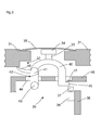
- FIG. 2 shows the embodiment FIG. 1 before performing the length adjustment of in FIG. 1 designated by the reference numeral 13 mechanical transmission element.
- FIG. 2 thus differs from the presentation FIG. 1 only to the effect that in place of the mechanical transmission element 13 a not yet matched in length mechanical transmission element 13 'occurs, the one in the FIG. 2 with x marked length over its nominal length survives.
- the desired length is in this case a length which leads to a protrusion of the mechanical transmission element 13, 13 'relative to the surface of the housing 11 attributable to an outer side of the optoelectronic sensor 10 around the in FIG FIG. 1 shown distance h leads.
- This means that the surface of the mechanical transmission element 13 'facing away from the switching element 17 is removed in its direction of movement by the distance x + h from a surface of the housing 11 attributable to an outside of the optoelectronic sensor 10.
- Fig. 3 shows a cross-sectional view of a section of another embodiment of the invention with a lever 40 as a mechanical transmission element. Shown is a section of an optoelectronic sensor 30 with an operating element, which represents the environment of the operating element.
- the operating element has a control surface 35, here shown as a teach membrane, which is arranged on a portion of a housing 31 of the optoelectronic sensor 30 on.
- the housing 31 has an in FIG. 3 not shown reference surface, which can be used for referencing the distance when adjusting the mechanical transmission element, that is, in this embodiment of the lever 40.
- the portion of the housing 31 is penetrated by a recess 32. At least in sections within the recess 32, the lever 40 is arranged so that it is movable upon actuation of the operating surface 35.
- an electronic card 36 is arranged, which is fixed in a holder, not shown.
- an electrical sensing element 38 is arranged with a switching element 37 so that upon actuation of the control surface 35, the lever 40 exerts a force on the switching element 37, which leads to a switching of the electrical sensing element 38.
- the lever 40 is mounted on one side slidably resting with a step 41 at a support point 42 and on the side at which the support point of the lever 40, in addition to a clamping body 43 in an undercut of a shaft 44 of a housing 31 of the optoelectronic sensor 30th arranged carrier 46 clipped.
- the other side of the lever 40 which triggers the switching of the electrical sensing element 38, has a nose 45 which engages behind an undercut 47 on the carrier 46, so that a captive against shaking out is given.
- a flexible spring element 48 is arranged, which, in particular in widest tolerance case, under bias on the housing 31 is supported.
- a pin 33 is arranged in this embodiment on the lever 40, via which a force exerted on the operating surface 35 on actuation of pressure in the lever 40, so that there is a one-sided tilting of the Lever 40 comes, which in turn triggers the actuation of the electrical sensing element 38 via the switching element 37.
- the adaptation preferably takes place on the pin 33. If it takes place by melting the material, the implementation of the adaptation is based on a side of the pin 33 facing the operating surface 35 arranged bead 34 made of molten material recognizable, so as to ensure that by means of the available, in FIG. 3 not shown working the switching of the electric probe element 38 can be triggered. Of course, all other procedures described above for length adjustment of the pin 33 are possible.
- the transmission element or the lever can be used in device housings of a wide variety of devices, such as measuring or control devices, in particular electronic or optoelectronic sensors, such as light barriers or light grids.
- the device housings are used in industries in which high demands are made on impermeability, temperature resistance, thermal shock resistance, mechanical abrasion resistance, resistance to external mechanical impacts, vapor and gas permeability, low moisture absorption and / or hygiene requirements, in particular in the food industry, the food industry. , Semi-luxury and / or beverage industry, the solar energy industry or the pharmaceutical industry, in which in particular the equipment used to be cleaned with chemicals, especially aggressive chemicals.
- the device housings meet the requirements up to IP69k.
Landscapes
- Switches Operated By Changes In Physical Conditions (AREA)
- Geophysics And Detection Of Objects (AREA)
Applications Claiming Priority (1)
| Application Number | Priority Date | Filing Date | Title |
|---|---|---|---|
| DE201010024900 DE102010024900B3 (de) | 2010-06-24 | 2010-06-24 | Verfahren zur Herstellung eines optoelektronischen Sensors mit einem Bedienelement und optoelektronischer Sensor mit einem Bedienelement |
Publications (2)
| Publication Number | Publication Date |
|---|---|
| EP2400664A1 true EP2400664A1 (fr) | 2011-12-28 |
| EP2400664B1 EP2400664B1 (fr) | 2013-11-06 |
Family
ID=43902319
Family Applications (1)
| Application Number | Title | Priority Date | Filing Date |
|---|---|---|---|
| EP11162554.7A Active EP2400664B1 (fr) | 2010-06-24 | 2011-04-15 | Procédé de fabrication d'un capteur optoélectronique doté d'un élément de commande |
Country Status (2)
| Country | Link |
|---|---|
| EP (1) | EP2400664B1 (fr) |
| DE (1) | DE102010024900B3 (fr) |
Families Citing this family (1)
| Publication number | Priority date | Publication date | Assignee | Title |
|---|---|---|---|---|
| DE202015104820U1 (de) | 2015-09-11 | 2016-12-14 | Sick Ag | Sensor |
Citations (3)
| Publication number | Priority date | Publication date | Assignee | Title |
|---|---|---|---|---|
| US4536625A (en) * | 1983-04-20 | 1985-08-20 | Bebie Alain M | Keyboard design |
| DE3214446C2 (de) * | 1982-04-20 | 1987-04-02 | Thyssen-M.A.N. Aufzüge GmbH, 7303 Neuhausen | Befehlsgeber, insbesondere für Aufzugssteuerungen |
| EP0777327A1 (fr) * | 1995-11-30 | 1997-06-04 | Haschkamp, Joachim, Dipl.-Ing. | Interrupteur à bouton-poussoir pour appareils électrodomestiques |
Family Cites Families (2)
| Publication number | Priority date | Publication date | Assignee | Title |
|---|---|---|---|---|
| JP3941357B2 (ja) * | 2000-08-21 | 2007-07-04 | 松下電器産業株式会社 | 押釦スイッチ及びこれを用いた複合スイッチ |
| KR101312136B1 (ko) * | 2006-06-22 | 2013-09-26 | 코박 컴퍼니 리미티드 | 시소키 대응 스위치 |
-
2010
- 2010-06-24 DE DE201010024900 patent/DE102010024900B3/de not_active Expired - Fee Related
-
2011
- 2011-04-15 EP EP11162554.7A patent/EP2400664B1/fr active Active
Patent Citations (3)
| Publication number | Priority date | Publication date | Assignee | Title |
|---|---|---|---|---|
| DE3214446C2 (de) * | 1982-04-20 | 1987-04-02 | Thyssen-M.A.N. Aufzüge GmbH, 7303 Neuhausen | Befehlsgeber, insbesondere für Aufzugssteuerungen |
| US4536625A (en) * | 1983-04-20 | 1985-08-20 | Bebie Alain M | Keyboard design |
| EP0777327A1 (fr) * | 1995-11-30 | 1997-06-04 | Haschkamp, Joachim, Dipl.-Ing. | Interrupteur à bouton-poussoir pour appareils électrodomestiques |
Also Published As
| Publication number | Publication date |
|---|---|
| EP2400664B1 (fr) | 2013-11-06 |
| DE102010024900B3 (de) | 2011-05-26 |
Similar Documents
| Publication | Publication Date | Title |
|---|---|---|
| WO2020152022A1 (fr) | Simulateur de pédale pour un véhicule | |
| WO2002076685A1 (fr) | Micropince | |
| DE102008053182A1 (de) | Elektronische Baugruppe mit Thermosicherung | |
| DE202009014353U1 (de) | Vakuumheber | |
| EP2006562B1 (fr) | Embrayage doté d'un dispositif de réglage | |
| DE202015101396U1 (de) | Steckerteil | |
| DE102014212570B4 (de) | Blockiereinrichtung für eine Schließfolgeregelungsvorrichtung einer zweiflügeligen Drehtüranlage | |
| WO2016079077A1 (fr) | Borne à ressort | |
| DE102010024900B3 (de) | Verfahren zur Herstellung eines optoelektronischen Sensors mit einem Bedienelement und optoelektronischer Sensor mit einem Bedienelement | |
| EP0508076A1 (fr) | Interrupteur de fin de course avec dépassement prédéterminé pour protéger l'objet dans des microscopes avec mise au point motorisée | |
| DE102010050399B4 (de) | Aktuator | |
| DE102016109486B3 (de) | Elektromagnetischer Schalter | |
| DE102017104638B4 (de) | Vorrichtung zum Umbugen von Überständen einer Kaschierung um einen Kantenbereich eines Werkstücks und ein entsprechendes Verfahren | |
| DE3710645A1 (de) | Druckschalter | |
| EP1251540B1 (fr) | Limiteur de température | |
| DE3922504A1 (de) | Axialer piezo - aktuator | |
| EP0091157A2 (fr) | Dispositif pour régler le pilon d'actionnement d'un dispositif de commande | |
| WO2009052954A2 (fr) | Servofrein à dépression et son procédé de réglage | |
| DE102016220746B4 (de) | Trägerplatte zum Halten einer Reibkupplung für ein Kraftfahrzeug mit zumindest einem Abstandselement | |
| DE3922917A1 (de) | Verfahren zur herstellung eines thermostatischen schalters mit engem betriebstemperaturbereich | |
| EP2095202A1 (fr) | Joystick pour un système de chargement de fret | |
| WO2009080402A1 (fr) | Boîtier avec un module disposé à l'intérieur | |
| DE10114530A1 (de) | Frankiermaschine mit Klemmeinrichtung für ein Poststück | |
| DE102024203381B4 (de) | Pneumatisches Ventil | |
| DE611446C (de) | Periodisch aus- und einschaltender Regelschalter, dessen Kontakte in einem vakuumdicht geschlossenen Glasgefaess angeordnet sind |
Legal Events
| Date | Code | Title | Description |
|---|---|---|---|
| AK | Designated contracting states |
Kind code of ref document: A1 Designated state(s): AL AT BE BG CH CY CZ DE DK EE ES FI FR GB GR HR HU IE IS IT LI LT LU LV MC MK MT NL NO PL PT RO RS SE SI SK SM TR |
|
| AX | Request for extension of the european patent |
Extension state: BA ME |
|
| PUAI | Public reference made under article 153(3) epc to a published international application that has entered the european phase |
Free format text: ORIGINAL CODE: 0009012 |
|
| 17P | Request for examination filed |
Effective date: 20111214 |
|
| 17Q | First examination report despatched |
Effective date: 20120313 |
|
| GRAP | Despatch of communication of intention to grant a patent |
Free format text: ORIGINAL CODE: EPIDOSNIGR1 |
|
| INTG | Intention to grant announced |
Effective date: 20130704 |
|
| GRAS | Grant fee paid |
Free format text: ORIGINAL CODE: EPIDOSNIGR3 |
|
| GRAA | (expected) grant |
Free format text: ORIGINAL CODE: 0009210 |
|
| AK | Designated contracting states |
Kind code of ref document: B1 Designated state(s): AL AT BE BG CH CY CZ DE DK EE ES FI FR GB GR HR HU IE IS IT LI LT LU LV MC MK MT NL NO PL PT RO RS SE SI SK SM TR |
|
| REG | Reference to a national code |
Ref country code: GB Ref legal event code: FG4D Free format text: NOT ENGLISH |
|
| REG | Reference to a national code |
Ref country code: CH Ref legal event code: EP |
|
| REG | Reference to a national code |
Ref country code: AT Ref legal event code: REF Ref document number: 640010 Country of ref document: AT Kind code of ref document: T Effective date: 20131215 |
|
| REG | Reference to a national code |
Ref country code: IE Ref legal event code: FG4D Free format text: LANGUAGE OF EP DOCUMENT: GERMAN |
|
| REG | Reference to a national code |
Ref country code: DE Ref legal event code: R096 Ref document number: 502011001585 Country of ref document: DE Effective date: 20140102 |
|
| REG | Reference to a national code |
Ref country code: NL Ref legal event code: VDEP Effective date: 20131106 |
|
| REG | Reference to a national code |
Ref country code: LT Ref legal event code: MG4D |
|
| PG25 | Lapsed in a contracting state [announced via postgrant information from national office to epo] |
Ref country code: HR Free format text: LAPSE BECAUSE OF FAILURE TO SUBMIT A TRANSLATION OF THE DESCRIPTION OR TO PAY THE FEE WITHIN THE PRESCRIBED TIME-LIMIT Effective date: 20131106 Ref country code: FI Free format text: LAPSE BECAUSE OF FAILURE TO SUBMIT A TRANSLATION OF THE DESCRIPTION OR TO PAY THE FEE WITHIN THE PRESCRIBED TIME-LIMIT Effective date: 20131106 Ref country code: NO Free format text: LAPSE BECAUSE OF FAILURE TO SUBMIT A TRANSLATION OF THE DESCRIPTION OR TO PAY THE FEE WITHIN THE PRESCRIBED TIME-LIMIT Effective date: 20140206 Ref country code: LT Free format text: LAPSE BECAUSE OF FAILURE TO SUBMIT A TRANSLATION OF THE DESCRIPTION OR TO PAY THE FEE WITHIN THE PRESCRIBED TIME-LIMIT Effective date: 20131106 Ref country code: IS Free format text: LAPSE BECAUSE OF FAILURE TO SUBMIT A TRANSLATION OF THE DESCRIPTION OR TO PAY THE FEE WITHIN THE PRESCRIBED TIME-LIMIT Effective date: 20140306 Ref country code: NL Free format text: LAPSE BECAUSE OF FAILURE TO SUBMIT A TRANSLATION OF THE DESCRIPTION OR TO PAY THE FEE WITHIN THE PRESCRIBED TIME-LIMIT Effective date: 20131106 Ref country code: SE Free format text: LAPSE BECAUSE OF FAILURE TO SUBMIT A TRANSLATION OF THE DESCRIPTION OR TO PAY THE FEE WITHIN THE PRESCRIBED TIME-LIMIT Effective date: 20131106 |
|
| PG25 | Lapsed in a contracting state [announced via postgrant information from national office to epo] |
Ref country code: ES Free format text: LAPSE BECAUSE OF FAILURE TO SUBMIT A TRANSLATION OF THE DESCRIPTION OR TO PAY THE FEE WITHIN THE PRESCRIBED TIME-LIMIT Effective date: 20131106 Ref country code: RS Free format text: LAPSE BECAUSE OF FAILURE TO SUBMIT A TRANSLATION OF THE DESCRIPTION OR TO PAY THE FEE WITHIN THE PRESCRIBED TIME-LIMIT Effective date: 20131106 Ref country code: LV Free format text: LAPSE BECAUSE OF FAILURE TO SUBMIT A TRANSLATION OF THE DESCRIPTION OR TO PAY THE FEE WITHIN THE PRESCRIBED TIME-LIMIT Effective date: 20131106 |
|
| PG25 | Lapsed in a contracting state [announced via postgrant information from national office to epo] |
Ref country code: PT Free format text: LAPSE BECAUSE OF FAILURE TO SUBMIT A TRANSLATION OF THE DESCRIPTION OR TO PAY THE FEE WITHIN THE PRESCRIBED TIME-LIMIT Effective date: 20140306 |
|
| PG25 | Lapsed in a contracting state [announced via postgrant information from national office to epo] |
Ref country code: EE Free format text: LAPSE BECAUSE OF FAILURE TO SUBMIT A TRANSLATION OF THE DESCRIPTION OR TO PAY THE FEE WITHIN THE PRESCRIBED TIME-LIMIT Effective date: 20131106 |
|
| REG | Reference to a national code |
Ref country code: DE Ref legal event code: R097 Ref document number: 502011001585 Country of ref document: DE |
|
| PG25 | Lapsed in a contracting state [announced via postgrant information from national office to epo] |
Ref country code: PL Free format text: LAPSE BECAUSE OF FAILURE TO SUBMIT A TRANSLATION OF THE DESCRIPTION OR TO PAY THE FEE WITHIN THE PRESCRIBED TIME-LIMIT Effective date: 20131106 Ref country code: RO Free format text: LAPSE BECAUSE OF FAILURE TO SUBMIT A TRANSLATION OF THE DESCRIPTION OR TO PAY THE FEE WITHIN THE PRESCRIBED TIME-LIMIT Effective date: 20131106 Ref country code: CZ Free format text: LAPSE BECAUSE OF FAILURE TO SUBMIT A TRANSLATION OF THE DESCRIPTION OR TO PAY THE FEE WITHIN THE PRESCRIBED TIME-LIMIT Effective date: 20131106 Ref country code: SK Free format text: LAPSE BECAUSE OF FAILURE TO SUBMIT A TRANSLATION OF THE DESCRIPTION OR TO PAY THE FEE WITHIN THE PRESCRIBED TIME-LIMIT Effective date: 20131106 |
|
| PLBE | No opposition filed within time limit |
Free format text: ORIGINAL CODE: 0009261 |
|
| STAA | Information on the status of an ep patent application or granted ep patent |
Free format text: STATUS: NO OPPOSITION FILED WITHIN TIME LIMIT |
|
| PG25 | Lapsed in a contracting state [announced via postgrant information from national office to epo] |
Ref country code: DK Free format text: LAPSE BECAUSE OF FAILURE TO SUBMIT A TRANSLATION OF THE DESCRIPTION OR TO PAY THE FEE WITHIN THE PRESCRIBED TIME-LIMIT Effective date: 20131106 |
|
| 26N | No opposition filed |
Effective date: 20140807 |
|
| REG | Reference to a national code |
Ref country code: DE Ref legal event code: R097 Ref document number: 502011001585 Country of ref document: DE Effective date: 20140807 |
|
| PG25 | Lapsed in a contracting state [announced via postgrant information from national office to epo] |
Ref country code: MC Free format text: LAPSE BECAUSE OF FAILURE TO SUBMIT A TRANSLATION OF THE DESCRIPTION OR TO PAY THE FEE WITHIN THE PRESCRIBED TIME-LIMIT Effective date: 20131106 Ref country code: LU Free format text: LAPSE BECAUSE OF FAILURE TO SUBMIT A TRANSLATION OF THE DESCRIPTION OR TO PAY THE FEE WITHIN THE PRESCRIBED TIME-LIMIT Effective date: 20140415 |
|
| REG | Reference to a national code |
Ref country code: IE Ref legal event code: MM4A |
|
| PG25 | Lapsed in a contracting state [announced via postgrant information from national office to epo] |
Ref country code: SI Free format text: LAPSE BECAUSE OF FAILURE TO SUBMIT A TRANSLATION OF THE DESCRIPTION OR TO PAY THE FEE WITHIN THE PRESCRIBED TIME-LIMIT Effective date: 20131106 |
|
| PG25 | Lapsed in a contracting state [announced via postgrant information from national office to epo] |
Ref country code: IE Free format text: LAPSE BECAUSE OF NON-PAYMENT OF DUE FEES Effective date: 20140415 |
|
| GBPC | Gb: european patent ceased through non-payment of renewal fee |
Effective date: 20150415 |
|
| PG25 | Lapsed in a contracting state [announced via postgrant information from national office to epo] |
Ref country code: GB Free format text: LAPSE BECAUSE OF NON-PAYMENT OF DUE FEES Effective date: 20150415 |
|
| PG25 | Lapsed in a contracting state [announced via postgrant information from national office to epo] |
Ref country code: MT Free format text: LAPSE BECAUSE OF FAILURE TO SUBMIT A TRANSLATION OF THE DESCRIPTION OR TO PAY THE FEE WITHIN THE PRESCRIBED TIME-LIMIT Effective date: 20131106 |
|
| REG | Reference to a national code |
Ref country code: FR Ref legal event code: PLFP Year of fee payment: 6 |
|
| PG25 | Lapsed in a contracting state [announced via postgrant information from national office to epo] |
Ref country code: SM Free format text: LAPSE BECAUSE OF FAILURE TO SUBMIT A TRANSLATION OF THE DESCRIPTION OR TO PAY THE FEE WITHIN THE PRESCRIBED TIME-LIMIT Effective date: 20131106 |
|
| PG25 | Lapsed in a contracting state [announced via postgrant information from national office to epo] |
Ref country code: GR Free format text: LAPSE BECAUSE OF FAILURE TO SUBMIT A TRANSLATION OF THE DESCRIPTION OR TO PAY THE FEE WITHIN THE PRESCRIBED TIME-LIMIT Effective date: 20140207 Ref country code: CY Free format text: LAPSE BECAUSE OF FAILURE TO SUBMIT A TRANSLATION OF THE DESCRIPTION OR TO PAY THE FEE WITHIN THE PRESCRIBED TIME-LIMIT Effective date: 20131106 Ref country code: BG Free format text: LAPSE BECAUSE OF FAILURE TO SUBMIT A TRANSLATION OF THE DESCRIPTION OR TO PAY THE FEE WITHIN THE PRESCRIBED TIME-LIMIT Effective date: 20131106 |
|
| PG25 | Lapsed in a contracting state [announced via postgrant information from national office to epo] |
Ref country code: BE Free format text: LAPSE BECAUSE OF FAILURE TO SUBMIT A TRANSLATION OF THE DESCRIPTION OR TO PAY THE FEE WITHIN THE PRESCRIBED TIME-LIMIT Effective date: 20140430 Ref country code: HU Free format text: LAPSE BECAUSE OF FAILURE TO SUBMIT A TRANSLATION OF THE DESCRIPTION OR TO PAY THE FEE WITHIN THE PRESCRIBED TIME-LIMIT; INVALID AB INITIO Effective date: 20110415 Ref country code: TR Free format text: LAPSE BECAUSE OF FAILURE TO SUBMIT A TRANSLATION OF THE DESCRIPTION OR TO PAY THE FEE WITHIN THE PRESCRIBED TIME-LIMIT Effective date: 20131106 |
|
| REG | Reference to a national code |
Ref country code: FR Ref legal event code: PLFP Year of fee payment: 7 |
|
| REG | Reference to a national code |
Ref country code: FR Ref legal event code: PLFP Year of fee payment: 8 |
|
| PG25 | Lapsed in a contracting state [announced via postgrant information from national office to epo] |
Ref country code: MK Free format text: LAPSE BECAUSE OF FAILURE TO SUBMIT A TRANSLATION OF THE DESCRIPTION OR TO PAY THE FEE WITHIN THE PRESCRIBED TIME-LIMIT Effective date: 20131106 |
|
| PG25 | Lapsed in a contracting state [announced via postgrant information from national office to epo] |
Ref country code: AL Free format text: LAPSE BECAUSE OF FAILURE TO SUBMIT A TRANSLATION OF THE DESCRIPTION OR TO PAY THE FEE WITHIN THE PRESCRIBED TIME-LIMIT Effective date: 20131106 |
|
| PGFP | Annual fee paid to national office [announced via postgrant information from national office to epo] |
Ref country code: IT Payment date: 20210430 Year of fee payment: 11 Ref country code: FR Payment date: 20210422 Year of fee payment: 11 |
|
| PGFP | Annual fee paid to national office [announced via postgrant information from national office to epo] |
Ref country code: AT Payment date: 20210420 Year of fee payment: 11 Ref country code: CH Payment date: 20210422 Year of fee payment: 11 |
|
| REG | Reference to a national code |
Ref country code: CH Ref legal event code: PL |
|
| REG | Reference to a national code |
Ref country code: AT Ref legal event code: MM01 Ref document number: 640010 Country of ref document: AT Kind code of ref document: T Effective date: 20220415 |
|
| PG25 | Lapsed in a contracting state [announced via postgrant information from national office to epo] |
Ref country code: LI Free format text: LAPSE BECAUSE OF NON-PAYMENT OF DUE FEES Effective date: 20220430 Ref country code: FR Free format text: LAPSE BECAUSE OF NON-PAYMENT OF DUE FEES Effective date: 20220430 Ref country code: CH Free format text: LAPSE BECAUSE OF NON-PAYMENT OF DUE FEES Effective date: 20220430 Ref country code: AT Free format text: LAPSE BECAUSE OF NON-PAYMENT OF DUE FEES Effective date: 20220415 |
|
| PG25 | Lapsed in a contracting state [announced via postgrant information from national office to epo] |
Ref country code: IT Free format text: LAPSE BECAUSE OF NON-PAYMENT OF DUE FEES Effective date: 20220415 |
|
| PGFP | Annual fee paid to national office [announced via postgrant information from national office to epo] |
Ref country code: DE Payment date: 20250417 Year of fee payment: 15 |