EP2400680A1 - Verringerung des Energieverbrauchs eines optischen Netzes - Google Patents
Verringerung des Energieverbrauchs eines optischen Netzes Download PDFInfo
- Publication number
- EP2400680A1 EP2400680A1 EP10006686A EP10006686A EP2400680A1 EP 2400680 A1 EP2400680 A1 EP 2400680A1 EP 10006686 A EP10006686 A EP 10006686A EP 10006686 A EP10006686 A EP 10006686A EP 2400680 A1 EP2400680 A1 EP 2400680A1
- Authority
- EP
- European Patent Office
- Prior art keywords
- upstream
- transmitter subsystem
- enabling
- transmitter
- start position
- Prior art date
- Legal status (The legal status is an assumption and is not a legal conclusion. Google has not performed a legal analysis and makes no representation as to the accuracy of the status listed.)
- Withdrawn
Links
- 230000003287 optical effect Effects 0.000 title claims abstract description 48
- 230000000116 mitigating effect Effects 0.000 title description 2
- 238000011144 upstream manufacturing Methods 0.000 claims abstract description 80
- 238000000034 method Methods 0.000 claims description 42
- 230000005540 biological transmission Effects 0.000 claims description 19
- 230000000977 initiatory effect Effects 0.000 claims description 2
- 230000000694 effects Effects 0.000 description 12
- 238000004891 communication Methods 0.000 description 7
- 230000008569 process Effects 0.000 description 6
- 238000005516 engineering process Methods 0.000 description 3
- 230000004913 activation Effects 0.000 description 2
- 230000009849 deactivation Effects 0.000 description 2
- 238000013461 design Methods 0.000 description 2
- 230000002123 temporal effect Effects 0.000 description 2
- 230000003213 activating effect Effects 0.000 description 1
- 230000032683 aging Effects 0.000 description 1
- 230000008878 coupling Effects 0.000 description 1
- 238000010168 coupling process Methods 0.000 description 1
- 238000005859 coupling reaction Methods 0.000 description 1
- 238000013500 data storage Methods 0.000 description 1
- 230000001419 dependent effect Effects 0.000 description 1
- 230000010354 integration Effects 0.000 description 1
- 239000013307 optical fiber Substances 0.000 description 1
- 238000012545 processing Methods 0.000 description 1
- 238000012546 transfer Methods 0.000 description 1
- 230000007704 transition Effects 0.000 description 1
Images



Classifications
-
- H—ELECTRICITY
- H04—ELECTRIC COMMUNICATION TECHNIQUE
- H04J—MULTIPLEX COMMUNICATION
- H04J3/00—Time-division multiplex systems
- H04J3/16—Time-division multiplex systems in which the time allocation to individual channels within a transmission cycle is variable, e.g. to accommodate varying complexity of signals, to vary number of channels transmitted
- H04J3/1694—Allocation of channels in TDM/TDMA networks, e.g. distributed multiplexers
-
- H—ELECTRICITY
- H04—ELECTRIC COMMUNICATION TECHNIQUE
- H04B—TRANSMISSION
- H04B10/00—Transmission systems employing electromagnetic waves other than radio-waves, e.g. infrared, visible or ultraviolet light, or employing corpuscular radiation, e.g. quantum communication
- H04B10/27—Arrangements for networking
-
- H—ELECTRICITY
- H04—ELECTRIC COMMUNICATION TECHNIQUE
- H04Q—SELECTING
- H04Q11/00—Selecting arrangements for multiplex systems
- H04Q11/0001—Selecting arrangements for multiplex systems using optical switching
- H04Q11/0062—Network aspects
- H04Q11/0067—Provisions for optical access or distribution networks, e.g. Gigabit Ethernet Passive Optical Network (GE-PON), ATM-based Passive Optical Network (A-PON), PON-Ring
-
- H—ELECTRICITY
- H04—ELECTRIC COMMUNICATION TECHNIQUE
- H04J—MULTIPLEX COMMUNICATION
- H04J3/00—Time-division multiplex systems
- H04J3/02—Details
- H04J3/06—Synchronising arrangements
- H04J3/0635—Clock or time synchronisation in a network
- H04J3/0682—Clock or time synchronisation in a network by delay compensation, e.g. by compensation of propagation delay or variations thereof, by ranging
-
- H—ELECTRICITY
- H04—ELECTRIC COMMUNICATION TECHNIQUE
- H04Q—SELECTING
- H04Q11/00—Selecting arrangements for multiplex systems
- H04Q11/0001—Selecting arrangements for multiplex systems using optical switching
- H04Q11/0062—Network aspects
- H04Q2011/0079—Operation or maintenance aspects
Definitions
- PONs Passive Optical Networks
- next-generation access network may be used as part of the implementation of next-generation access network.
- PONs With the large bandwidth of optical fibers, PONs can accommodate broadband voice, data, and video traffic simultaneously.
- PONs can be built with existing protocols, such as Ethernet and Asynchronous Transfer Mode (ATM), which facilitate interoperability between PONs and other network equipment.
- ATM Asynchronous Transfer Mode
- OLT Optical Line Terminal
- ONU Optical Network Unit
- the OLT generally resides in a Central Office (CO) and couples the optical access network to a backbone, which can be an external network belonging to, for example, an Internet Service Provider (ISP) or a local exchange carrier.
- ISP Internet Service Provider
- the ONU can reside in the residence or workplace of a customer and couples to the customer's network through a Customer-Premises Equipment (CPE).
- CPE Customer-Premises Equipment
- PON communications can include downstream traffic and upstream traffic.
- Downstream traffic refers to the direction from an OLT to one or more ONUs
- upstream traffic refers to the direction from an ONU to the OLT.
- data packets may be broadcast by the OLT to all ONUs and are selectively extracted by their destination ONUs.
- the ONUs share channel capacity and resources, because there is generally only one link coupling the passive optical coupler to the OLT.
- the optical transmitter may be designed to mitigate power consumption.
- the optical transmitter may be designed to receive signals that may be used to energize or power on transmitter components downstream from the optical transmitter at some advance time before an upstream timeslot assigned thereto is to occur. Advance energizing or powering on of the transmitter components of the optical transmitter may be configurable to take into consideration various optical transmitter types, aging of components in the transmitter, temperature variations, and the like.
- the optical transmitter may also be designed to receive instructions that cause the optical transmitter to transmit an upstream data burst about or at the start of the upstream timeslot.
- the optical transmitter may be designed to receive instructions that cause the transmitter components to power down or enter a reduced power operating mode at the end or near the end of the upstream timeslot. Enabling the transmitter components of the optical transmitted a determined time before the beginning of an assigned timeslot duration may reduce the amount of power consumed by apparatuses and devices deployed in the PON. Similarly, disabling the transmitter subsystem and components of the optical transmitter after a timeslot ends may reduce the amount of power consumed by apparatuses and devices deployed in the PON.
- the invention encompasses a method, comprising: determining a start position of an upstream timeslot; and enabling one or more transmitter subsystem components in advance of the start position of the upstream timeslot.
- a method comprising: determining a start position of an upstream timeslot; and enabling one or more transmitter subsystem components in advance of the start position of the upstream timeslot.
- the subsystem components may be in a low power state before being required to power up into a ready state in order to produce a modulation current and/or a laser bias current.
- the method further comprises disabling the one or more transmitter subsystem components substantially at an end position of the upstream timeslot. At least one effect of the foregoing is power savings once the disabling occurs.
- the method further comprises biasing an optical transmitter substantially at the start position of the upstream timeslot.
- the method further comprises obtaining the start position and the end position from a downstream data transmission. At least one effect of the foregoing is being capable of determining when to enable the subsystem components, and when it is appropriate, to disable the subsystem components.
- the one or more transmitter subsystem components are associated with laser driver used in a Passive Optical Network (PON).
- PON Passive Optical Network
- the one or more transmitter subsystem components are associated with an Optical Network Unit (ONU).
- ONU Optical Network Unit
- the act of enabling includes determining an amount of time necessary to enable the one or more transmitter subsystem components, and initiating enabling of the one or more transmitter subsystem components based on the determined amount of time. At least one effect of the foregoing is the determining the amount of time ensures that the one or more transmitter subsystems components are ready to supply the necessary signals to a laser so that an upstream data burst may be transmitted at the start position of the upstream timeslot.
- the act of enabling includes enabling at least a current source associated with a laser enable module. At least one effect of the foregoing is enabling the at least one current source associated with the laser enable module ensures the module is not in a full power state until it is necessary to start a power up process at some time before a laser must be optically energized to transmit an upstream burst of data.
- the act of enabling includes enabling at least a current source associated with a modulation module. At least one effect of the foregoing is enabling the at least one current source associated with the modulation module ensures the module is not in a full power state until it is necessary to start a power up process at some time before modulated data must be sent to a laser for burst transmission on a medium, such as an upstream communication channel.
- the act of enabling includes switching the one or more transmitter subsystem components from a substantially powered down state to a substantially powered up state. At least one effect of the foregoing is the one or more transmitter subsystem components is not in a full power state until it is necessary to start a power up process at some time before modulated data must be sent to a laser for burst transmission on a medium, such as an upstream communication channel.
- the act of enabling includes switching the one or more transmitter subsystem components from a partially powered down state to a substantially powered up state.
- the one or more transmitter subsystem components is not in a full power state, rather a partially powered state, until it is necessary to start a power up process at some time before modulated data must be sent to a laser for burst transmission on a medium, such as an upstream communication channel.
- the one or more transmitter subsystem components in a partially powered state before being enabled may enable the subsystem components to energize to an operational state in a quicker timeframe than if the subsystem components were at a fully powered down state.
- the act of disabling includes switching the one or more transmitter subsystem components from a substantially powered up state to a partially powered down state or a substantially powered down state. At least one effect of the foregoing is power savings may be achieved once the one or more transmitter subsystem components are transitioned to the partially powered down state.
- the invention encompasses an apparatus, comprising: a storage to store a start position of an upstream timeslot; a prediction engine to receive the start position stored in the storage; and logic to receive instructions from the prediction engine, the instructions indicating a time in advance of the start position of the upstream timeslot to initiate enabling at least one transmitter subsystem component.
- a storage to store a start position of an upstream timeslot
- a prediction engine to receive the start position stored in the storage
- the at least one transmitter subsystem component includes a modulation current source to provide a modulation current and a current source to provide an optical transmitter bias current.
- a modulation current source to provide a modulation current
- a current source to provide an optical transmitter bias current.
- the at least one transmitter subsystem component is in a partially powered down state or a substantially fully powered down state in advance of the logic executing the received instructions.
- the instructions further include the start position of the upstream timeslot, the logic to cause the at least one transmitter subsystem component to generate an output that enables the optical transmitter to transmit the upstream data burst at the start position of the upstream timeslot.
- the storage is to store an end position of the upstream timeslot
- the prediction engine to receive the end position stored in the storage
- the instructions further include the end position of the upstream timeslot
- the logic to cause the at least one transmitter subsystem component to enter at least a reduced power state at the end position of the upstream timeslot. At least one effect of the foregoing is power savings may be achieved once the at least one transmitter subsystem enters the reduced power state.
- the storage, the prediction engine and the logic are integrated on a single chip. Integration of at least the foregoing elements enables rapid enabling and disabling of modulation and laser current sources, clock trees and the like such that outstanding power savings may be achieved.
- FIG. 1 illustrates an exemplary implementation of a Passive Optical Network (PON).
- PON Passive Optical Network
- FIG. 2 illustrates an exemplary implementation of an Optical Network Unit Transmission system.
- FIG. 2A illustrates a detailed view of the laser driver introduced in FIG. 2.
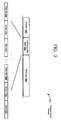
- FIG. 3 illustrates an exemplary downstream frame.
- FIG. 4 illustrates an exemplary laser or optical transmitter activation and deactivation procedure.
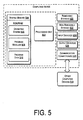
- FIG. 5 is an illustrative computing device that may be used to implement the devices, modules, apparatuses, and other hardware.
- FIG. 1 illustrates an exemplary implementation of a PON 100.
- the PON 100 may include Optical Network Units (ONUs) 102, 104 and 106 coupled to an Optical Line Terminal (OLT) 108 via an optical splitter 110.
- Traffic data transmission may be achieved, for example, by using Ethernet frames received and transmitted over two optical wavelengths, respectively, one for the downstream direction and another for the upstream direction.
- Downstream transmission from OLT 108 may be broadcast to all ONUs 102, 104 and 106.
- Each ONU 102, 104 and 106 may filter its respective data according to various known techniques.
- the ONUs 102, 104 and 106 may transmit respective upstream data to the OLT 108 during different timeslot allocated by the OLT 108 for each ONU 120.
- the splitter 110 may be used to split a single line into multiple lines.
- PONs may be classified into one of the following: an ATM PON (APON), a Broadband PON (BPON), an Ethernet PON (EPON or GE-PON), and a Gigabit PON (GPON).
- the APON uses the ATM protocol; the BPON is designed to provide broadband services over an ATM protocol; the EPON accommodates an Ethernet protocol; and the GPON is utilized when accommodating both the ATM protocol and the Ethernet protocol.
- Each type of PON is a standardized technology.
- the PON 100 illustrated in FIG. 1 may be such a standardized PON, or a PON that has yet to be standardized by a standard determining body.
- FIG. 2 illustrates an exemplary implementation of an ONU transmission system 200
- the ONUs 102, 104 and 106 may be implemented to include at least the ONU transmission system 200 illustrated in FIG. 2.
- Some or all of the elements and modules illustrated in FIG. 2 may be integrated on one chip. Alternatively, some or all of the elements illustrated may be discrete elements associated with one or more chips.
- the ONU transmission system 200 may include a processor 202.
- a storage 204, a frame generator 208 and a laser driver, transmit physical layer or optical driver 210 may be coupled to the processor 202.
- the laser driver 210 may be coupled to a laser 212.
- the laser driver 210 may be capable of putting the laser 212 in an active or inactive state.
- the laser driver 210 may include circuitry that may be enabled, in preparation for upstream transmission of data, some period of time before the laser 212 is activated to transmit data. Such circuitry may also be disabled after the laser 212 has completed a data burst transmission.
- the laser 212 may be a laser diode or other type of optical transmission apparatus.
- the ONU transmission system 200 may also include a prediction engine 214.
- the prediction engine 214 may be coupled to the storage 204, the frame generator 208 and the laser driver 210.
- the prediction engine 214 may send instructions to the laser driver 210 that cause the laser driver 210 to instruct the laser 212 to transition from an inactive state to an active state, or vice versa.
- the prediction engine 214 may send instructions to the laser driver 210 to prepare or power up various circuitry of the laser driver 210 prior to activating the laser 212 to transmit data.
- the prediction engine 214 may also send instructions to the laser driver 210 to power down various circuitry of the laser driver 210 after deactivating the laser 212.
- the prediction engine 214 may also receive or access information in the storage 204 and the frame generator 208.
- the prediction engine 214 may use some of all of the information to derive the instructions that the engine 214 sends to the laser driver 210.
- the frame generator 208 may generate upstream data frames that are for transmission to the OLT 108. These upstream data frames may be sent to the laser driver 210, which in turn may transmit the upstream data frames to the OLT 108 via the laser 212. In one implementation, the upstream data frames are transmitted to the OLT 108 in bursts, where each upstream data frame has a burst length defined by, for example, an upstream bandwidth map.
- FIG 2A illustrates an exemplary detailed view of the laser driver 210 introduced in FIG. 2.
- the laser driver 210 may include subsystem components, such as, a control logic 300, a modulation module 302 and a laser enable module 304.
- the control logic 300 may be coupled to the prediction engine 214.
- the modulation module 302 and the laser enable module 304 may each be coupled to the laser 212.
- the subsystem components may also include clock trees, data serializers and other active components and circuit elements.
- the control logic 300 may generate control and data signals that are communicated to the modulation module 302. These signals may cause the modulation module 302 to generate a modulation current that provides a burst of upstream data to the laser 212.
- the control logic 300 may also generate a control signal that causes the laser enable module 304 to generate a laser enable current that activates the laser 212 to produce an optical output signal to optically transmit the burst of upstream data associated with the modulation current.
- Signals generated by the control logic 300 may also cause the modulation module 302 and the laser enable module 304 to enter into a powered down state or a reduced power state.
- the modulation module 302 may include a current source that generates the modulation current. In one implementation, the modulation current is switched through a laser diode after being generated by the current source.
- a current control circuit may be coupled to the current source. This current control circuit may be controlled by the control logic 300 in a stepwise manner to adjust a level of the modulation current.
- the laser enable module 304 may include a current source that generates the laser enable current. In one implementation, the laser enable current is switched through a laser diode after being generated by the current source.
- a current control circuit may be coupled to the current source of the laser enable module 304. This current control circuit may be controlled by the control logic 300 in a stepwise manner to adjust a level of the laser enable current.
- FIG. 3 illustrates an exemplary downstream frame 300.
- the downstream frame 300 may be associated with the PON 100.
- the downstream frame 300 may include a header 302, an upstream bandwidth map 304 and a payload 306.
- the upstream bandwidth map 304 may include an ONU ID field 308, a start field 310 and an end field 312.
- the fields 308-312 are used to indicate a start position and an end position of each ONU upstream timeslot.
- Each ONU e.g., ONUs 102-106
- the upstream bandwidth map 304 may include timeslot information for the ONU 102.
- the start field 310 may identify that the start position of the upstream timeslot is the initial or 1 st timeslot and the end field 312 may identify that the end position of the upstream timeslot is the 100 th timeslot. Using this information, the ONU 102 is aware that it may send one or more upstream burst packets starting at the 1 st timeslot and ending at the 100 th timeslot.
- the upstream bandwidth map 304 may be stored in the storage 204.
- the exemplary downstream frame 300 does not necessarily include the upstream bandwidth map 304. Rather, the downstream frame 300 may carry the ONU ID field 308, the start field 310 and the end field 312 in other portions of the frame 300 or in another packaged format other than the upstream bandwidth map 304. Furthermore, the information carried in fields 308-312 may be included in a plurality of downstream frames or other frame types.
- exemplary procedures are described below. However, it should be understood that certain acts need not be performed in the order described, and may be modified, and/or may be omitted entirely, depending on the circumstances. Moreover, the acts described may be implemented by a computer, processor or other computing device based on instructions stored on one or more computer-readable storage media.
- the computer-readable storage media can be any available media that can be accessed by a computing device to implement the instructions stored thereon.
- the exemplary procedures described below may reference one or more of the exemplary devices described in FIGS. 1 - 3. Therefore, one or more of the devices and information illustrated in FIGS. 1 - 3 may used to implement the described procedures. However, the referenced devices are not limiting of the described procedures.
- FIG. 4 illustrates an exemplary optical transmitter subsystem activation and deactivation procedure.
- a start position of an upstream timeslot and an end position of the upstream timeslot may be determined.
- the predictive engine 214 obtains the start position and end position of the upstream timeslot from the storage 204.
- the predictive engine 214 may estimate or determine temporal related information that coincides with the start position and the end position of the upstream engine 214.
- Such temporal related information may take into consideration how long it takes the optical transmitter subsystem components (e.g., the modules 302 and 304) to power up to a ready state such that the modulation and laser enable currents may be supplied to the laser 212 in sufficient time to cause the laser 212 to transmit an upstream data burst at the start position of the upstream timeslot.
- the optical transmitter subsystem components may include some or all of the components associated with a transmit physical layer.
- an optical transmitter (e.g., the laser 212) is enabled at or about at a time the start position of the upstream timeslot is to occur.
- the predictive engine 214 sends instructions to the laser driver 210 that may be used thereby to cause the laser 212 to transmit an upstream data burst at the start position of the upstream timeslot. These instructions may be based on information received or otherwise obtained from the storage 204. The instructions from the predictive engine 214 may also enable the laser driver 210 to disable the laser 212 at the end position of the upstream timeslot, as is indicated at block 406.
- the predictive engine 214 may also send instructions to the laser driver 210 that may be used by the control logic 300 to power on, increase supplied power to, or "wakeup" various optical transmitter subsystem components at some calculated, determined or estimated time before biasing the laser 212 to transmit an upstream data burst.
- Such transmitter subsystem components may include, for example, the current source associated with the modulation module 302, the current source associated with the laser enable module 304, clock trees associated with the laser driver 210, and the current control circuits in the modules 302 and 304.
- the calculated, determined or estimated time generated by the predictive engine 214 takes into account when the laser 212 must be enabled to transmit the upstream data burst and how long it will take the optical transmitter subsystem components to reach the necessary operational state sufficient to supply the necessary current to the laser 212. Depending on the implementation and design particulars, it may be desirable to reduce an amount of energy or power consumed by the optical transmitter subsystem components by a particular percentage, as opposed to fully or nearly fully powering down those components. In such an implementation, the calculated, determined or estimated time generated by the predictive engine 214 may be shorter as compared to a calculated, determined or estimated time required to energize or power on subsystem components that are substantially in a powered off state.
- the predictive engine 214 may supply instructions that include distinct instruction sets.
- One instruction set indicates when the laser driver 210 is to cause the laser 212 to transmit an upstream data burst and when the laser 212 should be disabled.
- Another instruction set instructs the control logic 300 to, in anticipation of an impending upstream data burst transmission, wake, energize or other otherwise enable one or more transmitter subsystem components so that those components are ready to supply the necessary currents to the laser 212 at or around the start position of the upstream data burst.
- the another instruction set may include instructions that instruct the control logic 200 to reduce the power consumed by the subsystem components once the laser 212 completes the upstream data burst.
- the instructions to actually transmit an upstream data burst may originate from, for example, the frame generator 208 as opposed to the predictive engine 214.
- FIG. 5 is an illustrative computing device that may be used to implement the devices, modules, apparatuses, processes, procedures and hardware discussed herein.
- the computing device 500 includes at least one processing unit 502 and system memory 504.
- the system memory 504 may be volatile (such as RAM), non-volatile (such as ROM and flash memory) or some combination of the two.
- the system memory 504 typically includes an operating system 506, one or more program modules 508, and may include program data 510.
- the program modules 508 may realize the various elements described as being associated with the architectures and implementations herein. Other modules and device functionalities described herein may also be part of the program modules 508.
- the computing device 500 may have additional features or functionality. And, the computing device 500 may also include additional data storage devices (removable and/or non-removable) such as, for example, magnetic disks, optical disks, or tape. Such additional storage is illustrated in FIG. 5 by removable storage 520 and non-removable storage 522.
- Computer storage media may include volatile and nonvolatile, removable and non-removable media implemented in any method or technology for storage of information, such as computer readable instructions, data structures, program modules, or other data.
- the system memory 506, removable storage 520 and non-removable storage 522 are all examples of computer storage media.
- computer storage media includes, but is not limited to, RAM, ROM, EEPROM, flash memory or other memory technology, CD-ROM, digital versatile disks (DVD) or other optical storage, magnetic cassettes, magnetic tape, magnetic disk storage or other magnetic storage devices, or any other medium which can be used to store the desired information and which can be accessed by computing device 500. Any such computer storage media may be part of the device 500.
- Computing device 500 may also have input device(s) 524 such as keyboard, mouse, pen, voice input device, and touch input devices.
- Output device(s) 526 such as a display, speakers, and printer, may also be included. These devices are well known in the art and need not be discussed at length.
- the computing device 500 may also contain a communication connection 528 that allow the device to communicate with other computing devices 530, such as over a network.
- the communication connection may also enable the computing device 500 to wirelessly communicate with many different types of wireless service providers and medium.
- program modules include routines, programs, objects, components, data structures, and so forth, for performing particular tasks or implement particular abstract data types.
- program modules and the like may be executed as native code or may be downloaded and executed, such as in a virtual machine or other just-in-time compilation execution environment.
- functionality of the program modules may be combined or distributed as desired in various embodiments.
- An implementation of these modules and techniques may be stored on or transmitted across some form of computer readable media.
Landscapes
- Engineering & Computer Science (AREA)
- Computer Networks & Wireless Communication (AREA)
- Signal Processing (AREA)
- Computing Systems (AREA)
- Physics & Mathematics (AREA)
- Electromagnetism (AREA)
- Optical Communication System (AREA)
Priority Applications (5)
| Application Number | Priority Date | Filing Date | Title |
|---|---|---|---|
| EP10006686A EP2400680A1 (de) | 2010-06-28 | 2010-06-28 | Verringerung des Energieverbrauchs eines optischen Netzes |
| CN201110190792.XA CN102340709B (zh) | 2010-06-28 | 2011-06-27 | 用于与激光器一起使用的方法及装置 |
| TW100122600A TWI545965B (zh) | 2010-06-28 | 2011-06-28 | 用於與雷射器一起使用的方法及裝置 |
| US18/155,700 US12136998B2 (en) | 2010-06-28 | 2023-01-17 | Optical network power consumption mitigation |
| US18/936,951 US20250062851A1 (en) | 2010-06-28 | 2024-11-04 | Optical network power consumption mitigation |
Applications Claiming Priority (1)
| Application Number | Priority Date | Filing Date | Title |
|---|---|---|---|
| EP10006686A EP2400680A1 (de) | 2010-06-28 | 2010-06-28 | Verringerung des Energieverbrauchs eines optischen Netzes |
Publications (1)
| Publication Number | Publication Date |
|---|---|
| EP2400680A1 true EP2400680A1 (de) | 2011-12-28 |
Family
ID=42813239
Family Applications (1)
| Application Number | Title | Priority Date | Filing Date |
|---|---|---|---|
| EP10006686A Withdrawn EP2400680A1 (de) | 2010-06-28 | 2010-06-28 | Verringerung des Energieverbrauchs eines optischen Netzes |
Country Status (4)
| Country | Link |
|---|---|
| US (2) | US12136998B2 (de) |
| EP (1) | EP2400680A1 (de) |
| CN (1) | CN102340709B (de) |
| TW (1) | TWI545965B (de) |
Cited By (2)
| Publication number | Priority date | Publication date | Assignee | Title |
|---|---|---|---|---|
| EP3276610A1 (de) * | 2016-07-26 | 2018-01-31 | Samsung Electronics Co., Ltd | Elektronische vorrichtung und verfahren für den betrieb einer elektronischen vorrichtung |
| WO2023273855A1 (zh) * | 2021-06-29 | 2023-01-05 | 中兴通讯股份有限公司 | Onu的功耗控制方法、装置、电子设备及存储介质 |
Citations (4)
| Publication number | Priority date | Publication date | Assignee | Title |
|---|---|---|---|---|
| US20050041682A1 (en) * | 2003-08-18 | 2005-02-24 | Glen Kramer | Method and apparatus for reducing data burst overhead in an ethernet passive optical network |
| WO2007058708A1 (en) * | 2005-11-21 | 2007-05-24 | Tellabs Operations, Inc. | Systems and methods for dynamic alignment of data bursts conveyed over a passive optical network |
| EP2026508A1 (de) * | 2000-05-30 | 2009-02-18 | Nortel Networks Limited | Mehrfachzugriffsystem für ein Kommunikationsnetzwerk |
| EP2058961A1 (de) * | 2006-09-01 | 2009-05-13 | Huawei Technologies Co., Ltd. | Datenübertragungsverfahren, system und einrichtung |
Family Cites Families (10)
| Publication number | Priority date | Publication date | Assignee | Title |
|---|---|---|---|---|
| US6654565B2 (en) * | 2001-07-05 | 2003-11-25 | Wave7 Optics, Inc. | System and method for increasing upstream communication efficiency in an optical network |
| US7184667B2 (en) * | 2002-05-16 | 2007-02-27 | Intel Corporation | Wake-on LAN device |
| EP1864411B1 (de) * | 2005-03-31 | 2010-09-29 | Siemens Aktiengesellschaft | Adaptives ont für ein pon-netzwerk |
| US20070116466A1 (en) * | 2005-11-18 | 2007-05-24 | Broadlight Ltd. | Optical network unit (ONU) circuit |
| KR100663462B1 (ko) * | 2005-11-23 | 2007-01-02 | 삼성전자주식회사 | 수동형 광 가입자 망 |
| US7356058B2 (en) * | 2005-12-29 | 2008-04-08 | Broadlight Ltd. | Adaptive laser diode driver and method |
| US7505495B2 (en) * | 2005-12-30 | 2009-03-17 | Agere Systems Inc. | Optical assembly comprising multiple semiconductor optical devices and an active cooling device |
| WO2010024353A1 (ja) * | 2008-08-28 | 2010-03-04 | Toto株式会社 | 耐蝕性部材およびその製造方法 |
| US8498534B2 (en) * | 2008-11-05 | 2013-07-30 | Broadcom Corporation | Epon with power-saving features |
| US10069586B2 (en) * | 2010-06-28 | 2018-09-04 | Lantiq Deutschland Gmbh | Optical network power consumption mitigation |
-
2010
- 2010-06-28 EP EP10006686A patent/EP2400680A1/de not_active Withdrawn
-
2011
- 2011-06-27 CN CN201110190792.XA patent/CN102340709B/zh active Active
- 2011-06-28 TW TW100122600A patent/TWI545965B/zh not_active IP Right Cessation
-
2023
- 2023-01-17 US US18/155,700 patent/US12136998B2/en active Active
-
2024
- 2024-11-04 US US18/936,951 patent/US20250062851A1/en active Pending
Patent Citations (4)
| Publication number | Priority date | Publication date | Assignee | Title |
|---|---|---|---|---|
| EP2026508A1 (de) * | 2000-05-30 | 2009-02-18 | Nortel Networks Limited | Mehrfachzugriffsystem für ein Kommunikationsnetzwerk |
| US20050041682A1 (en) * | 2003-08-18 | 2005-02-24 | Glen Kramer | Method and apparatus for reducing data burst overhead in an ethernet passive optical network |
| WO2007058708A1 (en) * | 2005-11-21 | 2007-05-24 | Tellabs Operations, Inc. | Systems and methods for dynamic alignment of data bursts conveyed over a passive optical network |
| EP2058961A1 (de) * | 2006-09-01 | 2009-05-13 | Huawei Technologies Co., Ltd. | Datenübertragungsverfahren, system und einrichtung |
Cited By (3)
| Publication number | Priority date | Publication date | Assignee | Title |
|---|---|---|---|---|
| EP3276610A1 (de) * | 2016-07-26 | 2018-01-31 | Samsung Electronics Co., Ltd | Elektronische vorrichtung und verfahren für den betrieb einer elektronischen vorrichtung |
| US10313013B2 (en) | 2016-07-26 | 2019-06-04 | Samsung Electronics Co., Ltd. | Electronic apparatus and method of operating the electronic apparatus |
| WO2023273855A1 (zh) * | 2021-06-29 | 2023-01-05 | 中兴通讯股份有限公司 | Onu的功耗控制方法、装置、电子设备及存储介质 |
Also Published As
| Publication number | Publication date |
|---|---|
| TW201206204A (en) | 2012-02-01 |
| CN102340709B (zh) | 2016-03-02 |
| US20250062851A1 (en) | 2025-02-20 |
| CN102340709A (zh) | 2012-02-01 |
| US12136998B2 (en) | 2024-11-05 |
| US20230155710A1 (en) | 2023-05-18 |
| TWI545965B (zh) | 2016-08-11 |
Similar Documents
| Publication | Publication Date | Title |
|---|---|---|
| US11664916B2 (en) | Optical network power consumption mitigation | |
| US20250062851A1 (en) | Optical network power consumption mitigation | |
| CN105075177B (zh) | 无源光网络中下行突发传输 | |
| US8699885B2 (en) | Power control in an optical network unit | |
| US10666468B2 (en) | Channel training method, apparatus, and system | |
| US8879594B2 (en) | Efficient power control for an automatic laser driver | |
| US20140161456A1 (en) | Network system, station-side apparatus, and method of controlling communications | |
| JP5328994B2 (ja) | 中継装置、局側光通信装置、通信システムおよび帯域割当方法 | |
| KR102423938B1 (ko) | 버스트 모드로 광송신을 하기 위한 광망 종단 장치 | |
| US20130294774A1 (en) | Optical Line Terminal, Optical Network Unit and Passive Optical Network System | |
| KR20170010006A (ko) | 광 패킷 전송 방법 및 장치, 처리 방법 및 광 스위칭 장치 | |
| US11855756B2 (en) | Status control method, data sending method, and terminal | |
| JP5084629B2 (ja) | 加入者終端装置および電源制御方法 | |
| US11294335B2 (en) | Method, device and computer-readable medium of managing a clock circuit | |
| JP5650616B2 (ja) | 光送受信装置の制御方法、光送受信装置、及び光通信システム | |
| WO2016157626A1 (ja) | 局側装置および通信制御方法 | |
| CN109560873A (zh) | 光线路终端olt及其休眠控制方法、控制装置 | |
| CN120980377A (zh) | 无源光网络pon共存方法及装置 | |
| US20130188953A1 (en) | Optical network system and method for controlling optical network system | |
| Liu | An FPGA implementation of a sleep enabled PON system | |
| CN112740580A (zh) | 光网络节能 |
Legal Events
| Date | Code | Title | Description |
|---|---|---|---|
| AK | Designated contracting states |
Kind code of ref document: A1 Designated state(s): AL AT BE BG CH CY CZ DE DK EE ES FI FR GB GR HR HU IE IS IT LI LT LU LV MC MK MT NL NO PL PT RO SE SI SK SM TR |
|
| AX | Request for extension of the european patent |
Extension state: BA ME RS |
|
| PUAI | Public reference made under article 153(3) epc to a published international application that has entered the european phase |
Free format text: ORIGINAL CODE: 0009012 |
|
| 17P | Request for examination filed |
Effective date: 20120626 |
|
| RAP1 | Party data changed (applicant data changed or rights of an application transferred) |
Owner name: LANTIQ DEUTSCHLAND GMBH |
|
| STAA | Information on the status of an ep patent application or granted ep patent |
Free format text: STATUS: THE APPLICATION IS DEEMED TO BE WITHDRAWN |
|
| 18D | Application deemed to be withdrawn |
Effective date: 20170103 |