EP2401496B1 - Dispositif de capture d'énergie - Google Patents
Dispositif de capture d'énergie Download PDFInfo
- Publication number
- EP2401496B1 EP2401496B1 EP10711250.0A EP10711250A EP2401496B1 EP 2401496 B1 EP2401496 B1 EP 2401496B1 EP 10711250 A EP10711250 A EP 10711250A EP 2401496 B1 EP2401496 B1 EP 2401496B1
- Authority
- EP
- European Patent Office
- Prior art keywords
- column
- support structure
- capture device
- power capture
- piston
- Prior art date
- Legal status (The legal status is an assumption and is not a legal conclusion. Google has not performed a legal analysis and makes no representation as to the accuracy of the status listed.)
- Not-in-force
Links
- 230000033001 locomotion Effects 0.000 claims description 46
- XLYOFNOQVPJJNP-UHFFFAOYSA-N water Substances O XLYOFNOQVPJJNP-UHFFFAOYSA-N 0.000 claims description 26
- 230000000712 assembly Effects 0.000 claims description 24
- 238000000429 assembly Methods 0.000 claims description 24
- 239000012530 fluid Substances 0.000 claims description 12
- 230000004044 response Effects 0.000 claims description 4
- 230000000295 complement effect Effects 0.000 claims description 3
- 230000000694 effects Effects 0.000 claims description 3
- 230000005540 biological transmission Effects 0.000 description 6
- 230000005611 electricity Effects 0.000 description 6
- 238000010276 construction Methods 0.000 description 4
- 230000010355 oscillation Effects 0.000 description 4
- 238000005516 engineering process Methods 0.000 description 3
- 238000007667 floating Methods 0.000 description 3
- 230000001419 dependent effect Effects 0.000 description 2
- 238000006073 displacement reaction Methods 0.000 description 2
- 239000000463 material Substances 0.000 description 2
- 238000005259 measurement Methods 0.000 description 2
- 239000004033 plastic Substances 0.000 description 2
- 229920003023 plastic Polymers 0.000 description 2
- 239000006096 absorbing agent Substances 0.000 description 1
- 238000006243 chemical reaction Methods 0.000 description 1
- 230000006835 compression Effects 0.000 description 1
- 238000007906 compression Methods 0.000 description 1
- 230000008878 coupling Effects 0.000 description 1
- 238000010168 coupling process Methods 0.000 description 1
- 238000005859 coupling reaction Methods 0.000 description 1
- 238000013016 damping Methods 0.000 description 1
- 230000007613 environmental effect Effects 0.000 description 1
- 210000003414 extremity Anatomy 0.000 description 1
- 239000004744 fabric Substances 0.000 description 1
- 230000004907 flux Effects 0.000 description 1
- 229910052734 helium Inorganic materials 0.000 description 1
- 239000001307 helium Substances 0.000 description 1
- SWQJXJOGLNCZEY-UHFFFAOYSA-N helium atom Chemical compound [He] SWQJXJOGLNCZEY-UHFFFAOYSA-N 0.000 description 1
- 230000006872 improvement Effects 0.000 description 1
- 210000003141 lower extremity Anatomy 0.000 description 1
- 230000013011 mating Effects 0.000 description 1
- 230000007246 mechanism Effects 0.000 description 1
- 238000000034 method Methods 0.000 description 1
- 230000008569 process Effects 0.000 description 1
- 239000013535 sea water Substances 0.000 description 1
- 239000003643 water by type Substances 0.000 description 1
Images


Classifications
-
- F—MECHANICAL ENGINEERING; LIGHTING; HEATING; WEAPONS; BLASTING
- F03—MACHINES OR ENGINES FOR LIQUIDS; WIND, SPRING, OR WEIGHT MOTORS; PRODUCING MECHANICAL POWER OR A REACTIVE PROPULSIVE THRUST, NOT OTHERWISE PROVIDED FOR
- F03B—MACHINES OR ENGINES FOR LIQUIDS
- F03B13/00—Adaptations of machines or engines for special use; Combinations of machines or engines with driving or driven apparatus; Power stations or aggregates
- F03B13/12—Adaptations of machines or engines for special use; Combinations of machines or engines with driving or driven apparatus; Power stations or aggregates characterised by using wave or tide energy
- F03B13/14—Adaptations of machines or engines for special use; Combinations of machines or engines with driving or driven apparatus; Power stations or aggregates characterised by using wave or tide energy using wave energy
- F03B13/16—Adaptations of machines or engines for special use; Combinations of machines or engines with driving or driven apparatus; Power stations or aggregates characterised by using wave or tide energy using wave energy using the relative movement between a wave-operated member, i.e. a "wom" and another member, i.e. a reaction member or "rem"
- F03B13/20—Adaptations of machines or engines for special use; Combinations of machines or engines with driving or driven apparatus; Power stations or aggregates characterised by using wave or tide energy using wave energy using the relative movement between a wave-operated member, i.e. a "wom" and another member, i.e. a reaction member or "rem" wherein both members, i.e. wom and rem are movable relative to the sea bed or shore
-
- F—MECHANICAL ENGINEERING; LIGHTING; HEATING; WEAPONS; BLASTING
- F03—MACHINES OR ENGINES FOR LIQUIDS; WIND, SPRING, OR WEIGHT MOTORS; PRODUCING MECHANICAL POWER OR A REACTIVE PROPULSIVE THRUST, NOT OTHERWISE PROVIDED FOR
- F03B—MACHINES OR ENGINES FOR LIQUIDS
- F03B13/00—Adaptations of machines or engines for special use; Combinations of machines or engines with driving or driven apparatus; Power stations or aggregates
- F03B13/12—Adaptations of machines or engines for special use; Combinations of machines or engines with driving or driven apparatus; Power stations or aggregates characterised by using wave or tide energy
- F03B13/14—Adaptations of machines or engines for special use; Combinations of machines or engines with driving or driven apparatus; Power stations or aggregates characterised by using wave or tide energy using wave energy
- F03B13/16—Adaptations of machines or engines for special use; Combinations of machines or engines with driving or driven apparatus; Power stations or aggregates characterised by using wave or tide energy using wave energy using the relative movement between a wave-operated member, i.e. a "wom" and another member, i.e. a reaction member or "rem"
- F03B13/18—Adaptations of machines or engines for special use; Combinations of machines or engines with driving or driven apparatus; Power stations or aggregates characterised by using wave or tide energy using wave energy using the relative movement between a wave-operated member, i.e. a "wom" and another member, i.e. a reaction member or "rem" where the other member, i.e. rem is fixed, at least at one point, with respect to the sea bed or shore
-
- F—MECHANICAL ENGINEERING; LIGHTING; HEATING; WEAPONS; BLASTING
- F03—MACHINES OR ENGINES FOR LIQUIDS; WIND, SPRING, OR WEIGHT MOTORS; PRODUCING MECHANICAL POWER OR A REACTIVE PROPULSIVE THRUST, NOT OTHERWISE PROVIDED FOR
- F03B—MACHINES OR ENGINES FOR LIQUIDS
- F03B13/00—Adaptations of machines or engines for special use; Combinations of machines or engines with driving or driven apparatus; Power stations or aggregates
- F03B13/12—Adaptations of machines or engines for special use; Combinations of machines or engines with driving or driven apparatus; Power stations or aggregates characterised by using wave or tide energy
- F03B13/26—Adaptations of machines or engines for special use; Combinations of machines or engines with driving or driven apparatus; Power stations or aggregates characterised by using wave or tide energy using tide energy
-
- F—MECHANICAL ENGINEERING; LIGHTING; HEATING; WEAPONS; BLASTING
- F05—INDEXING SCHEMES RELATING TO ENGINES OR PUMPS IN VARIOUS SUBCLASSES OF CLASSES F01-F04
- F05B—INDEXING SCHEME RELATING TO WIND, SPRING, WEIGHT, INERTIA OR LIKE MOTORS, TO MACHINES OR ENGINES FOR LIQUIDS COVERED BY SUBCLASSES F03B, F03D AND F03G
- F05B2250/00—Geometry
- F05B2250/40—Movement of component
- F05B2250/44—Movement of component one element moving inside another one, e.g. wave-operated member (wom) moving inside another member (rem)
-
- Y—GENERAL TAGGING OF NEW TECHNOLOGICAL DEVELOPMENTS; GENERAL TAGGING OF CROSS-SECTIONAL TECHNOLOGIES SPANNING OVER SEVERAL SECTIONS OF THE IPC; TECHNICAL SUBJECTS COVERED BY FORMER USPC CROSS-REFERENCE ART COLLECTIONS [XRACs] AND DIGESTS
- Y02—TECHNOLOGIES OR APPLICATIONS FOR MITIGATION OR ADAPTATION AGAINST CLIMATE CHANGE
- Y02E—REDUCTION OF GREENHOUSE GAS [GHG] EMISSIONS, RELATED TO ENERGY GENERATION, TRANSMISSION OR DISTRIBUTION
- Y02E10/00—Energy generation through renewable energy sources
- Y02E10/30—Energy from the sea, e.g. using wave energy or salinity gradient
Definitions
- the present invention relates to a power capture device and, in a preferred embodiment, to an ocean based power generating device.
- a vast array of technologies have been proposed in the generation of power from the oceans in a number of wave and tidal generation technologies which are at various stages of development. A selection of the main system types are described below.
- Wave energy devices operate using one of a number of principles. Devices can be located on the shoreline, near shore or off shore. Early devices were shoreline based but more recent concepts have focused on off shore sites where wave energies are higher but conditions can be more challenging.
- waves are trapped in a chamber and the rise and fall of the water moves a column of air which drives a turbine.
- These devices can be located either on the shoreline (e.g. built into cliffs or break waters) or in floating offshore devices.
- shoreline based systems use a gradually tapering channel (hence TAP - CHAN) to amplify wave heights to a level that allows a raised reservoir or lagoon a few metres above normal sea level to be filled. Electricity is generated as the water passes from the reservoir back to the sea via a low head turbine.
- a gradually tapering channel (hence TAP - CHAN) to amplify wave heights to a level that allows a raised reservoir or lagoon a few metres above normal sea level to be filled. Electricity is generated as the water passes from the reservoir back to the sea via a low head turbine.
- the motion of a buoyant object is used to drive a generator.
- the complete system comprises a float (which may rest at or under the surface of the sea), generating equipment and, in most cases, a platform/foundations fixed to the seabed.
- the movement of the float (usually relative to the fixed platform) drives the generating equipment to produce electricity.
- These devices use the relative motion of a series of floating structures to generate electricity.
- the vertical and/or horizontal movement between the floats can be captured using either hydraulic or mechanical couplings.
- Tidal devices fall into two main categories: Tidal barrages, and Tidal current turbines. Barrages have already been tried and installed in a number of places, and whilst they have proved successful, their cost and environmental impact mean that current turbines are the leading technology concepts being proposed at present.
- Tidal barrages are installed in tidal estuaries or inlets and work by holding back the flow of water at high/low tides. Once a sufficient head of water has been formed, the water can be released through turbines to generate electricity.
- tidal stream turbines When using the same principle as wind turbines, tidal stream turbines generate power directly from the flow of the tides. They are installed in the sea at places with fast tidal currents or where continuous currents are fast and strong enough to produce energy from the water flow.
- the turbines can be orientated either horizontally or vertically and systems can be either floating or secured directly to the seabed.
- the document DE 20201389 U discloses an example of a power capture device.
- the present invention does not utilise any of the principles adopted in the known devices referred to above but instead harnesses the inertial force, e.g. tide, swell, waves, current, from an ocean immersed mass relative to a fixed point.
- the preferred embodiment of the device of the present invention takes the form of an elongate buoyant column journalled in a support structure and which can move in three dimensions which, seen from above, appears as a classic lissajou motion and a superimposed movement caused by vortex shedding.
- the buoyant pivotal column moves like an inverted pendulum in the wind. However, unlike a pendulum, whose bob describes in two dimensions an arc of fixed radius (the length of the string), a pivotal column moves (in two dimensions), along the appropriate horizontal chord of a circle. In three dimensions, seen from above, this appears as a classic Lissajou figure of eight but the column is subject to vortex induced motion which keeps it virtually in constant motion.
- Vortex induced motion is an unsteady flow that takes place in special flow velocities (according to the size and shape of the cylindrical body). In this flow, vortices are created at the back of the body and detach periodically from either side of the body and this is known as vortex shedding. Vortex shedding is caused when a fluid flows past a blunt object. The fluid flow past the object creates alternating low-pressure vortices on the downstream side of the object. The object will tend to move towards the low-pressure zone. Eventually, if the frequency of vortex shedding matches the resonance frequency of the structure, the structure will begin to resonate and the structure's movement can become self-sustaining.
- the present invention provides a power capture device utilising movement of a fluid body according to claim 1, which device comprises an elongate buoyant column journalled in a support structure for universal movement relative thereto, the support structure being adapted to be secured to the ground with the column disposed in the path of fluid flow so that the column experiences vortex induced motion which creates universal motion relative to the support structure automatically in response to force transmitted by fluid flow past the column, wherein the support structure includes actuating means to convert movement of the column into an operative force to drive electrical power generating means.
- the buoyant column may be adapted to stand upright relative to the support structure.
- the buoyant column may be adapted to be suspended from the support structure.
- the support structure may be adapted to be secured to the bed or banks of a body of water, such as the sea bed or a river bed or bank and wherein the column is disposed for at least partially submerged universal motion relative to the support structure automatically in response to force transmitted by the flow of water past the column.
- the actuating means may comprise a plurality of piston and cylinder assemblies.
- an array of piston and cylinder assemblies is provided by the support structure, and wherein the column is adapted to actuate the piston and cylinder assemblies in random sequence as a result of movement of the column relative to the support structure.
- the array of piston and cylinder assemblies are disposed to present means to actuate the heads of the pistons to the supported end of the column which causes reciprocal movement of the pistons in random sequence as a result of said movement of the column.
- the array of piston and cylinder assemblies are disposed in a part spherical arrangement and the supported end of the column includes a spherical actuator which rides around the part spherical arrangement of the piston and cylinder assemblies to cause said reciprocal movement of the pistons in random sequence.
- the piston and cylinder assemblies are arranged in a plurality of concentric annular banks within a part spherical recess within the support structure.
- the array of piston and cylinder assemblies may be hydraulically or pneumatically connected to drive electrical power generating means contained within the support structure.
- the array of piston and cylinder assemblies may be mechanically actuated to drive electrical power generating means contained within the support structure.
- the column may be journalled in the support structure by means of a ball and socket joint arrangement.
- the supported end of the column includes the ball of the ball and socket joint arrangement and the socket of the ball and socket joint arrangement is provided by a concave annulus within the support structure.
- the column includes an extension within the support structure beyond the ball of the ball and socket joint arrangement which actuates said means in random sequence to drive electrical power generating means as a result of movement of the column relative to the support structure.
- the support structure and the column may have complementary formed faces to limit the universal movement of the column relative to the support structure.
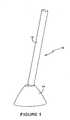
- the device 10 comprises an elongate buoyant column 12, which is received and journalled in a support structure 14 adapted to be secured to the sea bed. It is envisaged that the column may have a length of the order of 200m and be of up to 40m in diameter. It is therefore a massive structure but may be formed from a suitable plastics material.
- the column 12 can be formed from a stack of modular sections of annular form. If the column is formed as a modular structure its height can be varied for different water depths. Moreover, although this structure is non-intrusive when installed, it readily can be repaired if damaged by impact.
- the column is journalled in the support structure by means of a ball and socket joint adjacent the upper end of the support structure.
- the ball and socket joint comprises a spherical portion 16 ( Figures 2 and 4 ) of the column adjacent its lower extremity and a concave annulus 18 formed in the support structure.
- the column can move universally relative to the support structure automatically in response to force transmitted by the various complex movements of the ocean.
- the overall movement of the column is limited by shaped complementary mating bearing surfaces 20, 22 provided by the column and the head 24 of the support structure, respectively.
- the extremity of the supported end of the column is formed with a spherical actuator 26 which is spaced from the spherical portion 16 by an integral arm 28.
- the spherical actuator 26 operates within a semi-spherical bowl 30 formed within the support structure.
- the spherical actuator 30 rides around protruding spheres which actuate the pistons in an array 32 of piston and cylinder assemblies.
- the pistons are actuated in random sequence consequent upon the movement of the column.
- the array of piston and cylinder assemblies are arranged in the bowl 30 in a number of concentric annular banks, e.g. 34, 36, 38.
- the piston and cylinder assemblies are connected by suitable hydraulic and/or pneumatic circuits to a number of electrical power generators 40 which are housed in a chamber 42 of the support structure disposed below the bowl 30.
- the actuation of the pistons and the connecting fluidic circuitry is such that continuous generation of electrical power is obtained through the constant motion of the column.
- the electrical power generating means may be housed separately from the support structure and may be located on-shore so that the device pumps hydraulic fluid, which could be sea water, to energy accumulators for the remote generation of electricity.
- the piston and cylinder assembly 44 comprises a housing in the form of a cylindrical sleeve 46, each of which is contained in bores formed in the semi-spherical bowl 30.
- One end of the sleeve 46 provides a seat for a spherical force transmission element, which preferably is a ball 48.
- Ball 48 can rotate relative to the sleeve 46 and move axially within it, but is constrained from being dislodged from the open top of the sleeve by an inwardly directed lip 47.
- the spherical actuator 26 at the supported end of the column 12 periodically bears down on each of the transmission balls 48 as the spherical actuator passes over them and depresses the transmission ball against a compression spring into the sleeve.
- the transmission ball abuts a spherical end 50 of a piston rod 52 of a hydraulic ram 54.
- axial movement of the transmission ball 48 down the sleeve 46 depresses the piston rod against the force of a return spring 56 to operate the piston of the hydraulic ram.
- the hydraulic ram causes hydraulic fluid to be transferred to an accumulator means which, in turn, drives one or more electrical generators.
- the piston and cylinder assembly 44a does not involve the inclusion of hydraulic or pneumatic components but rather is a mechanical assembly.
- the piston rod 52a reciprocates within sleeve 46a, against the force of return spring 56a, and protrudes through an opening 58 formed in an end wall 60 of the sleeve.
- the exposed lower end of the piston rod is formed with an axial gear 62 which meshes with and drives planet gear wheel 64 in consequence of reciprocal movement of the piston rod 52a.
- Gear 64 meshes with and drives a sun drive gear 66 of an electrical generator to produce electrical power.
- FIGS 7 and 8 of the drawings illustrate the phenomena of vortex shedding to which the buoyant column is subject when disposed in a fluid flow.
- the buoyant column is designed to extract energy from tidal flows of 2 -6 m/s, and is caused to oscillate from side to side by the process of vortex shedding.
- the power is based on standard energy flux and area, with the area being the frontage area of the device (hd). This is very much an estimate, and it may be that in reality it is smaller, or on the other hand , it may be larger as the area swept out by the device may be the real area ie 2h ⁇ .
- P w 0.5 ⁇ A ⁇ ⁇ ⁇ u 3 Watts
- the following calculations are for a column length of 200m from pivot to water surface.
- the column diameter varies from 5 to 40m, and the water velocity runs up to 6m/s.
- the energy captured in each cycle is strongly dependent on device diameter and water velocity.
- the period of vortex induced oscillations is shown below, and is also strongly dependent on device diameter and water velocity.
- the single curve applies to all water velocities.
- the device could be installed in an inverted attitude so that the column is suspended from the support structure in a body of water.
- the lower free end of the column would be weighted and would act like a pendulum with universal motion.
- the support structure itself would be supported by a gantry spanning a natural or man-made channel through which water flows or the gantry could span the banks of a river.
- the device could be modified for use as a wind powered device.
- the column could be formed from a light weight fabric, plastics or other suitable material providing a sealed buoyant cylinder filled with air or helium.
Landscapes
- Engineering & Computer Science (AREA)
- Chemical & Material Sciences (AREA)
- Combustion & Propulsion (AREA)
- Mechanical Engineering (AREA)
- General Engineering & Computer Science (AREA)
- Life Sciences & Earth Sciences (AREA)
- General Life Sciences & Earth Sciences (AREA)
- Oceanography (AREA)
- Other Liquid Machine Or Engine Such As Wave Power Use (AREA)
Claims (16)
- Dispositif de capture d'énergie (10) pour l'utilisation du mouvement d'un corps fluide, le dispositif comprenant une colonne allongée flottant dans un fluide vers une orientation préférentielle et en association articulée, à côté d'une extrémité, avec une structure de support (14) pour un mouvement universel autour de celle-ci, défini par l'association articulée, la structure de support (14) étant adaptée pour être fixée avec la colonne (12) disposée dans un flux de fluide pendant l'utilisation, de manière à ce que de par sa forme, sa position et sa longueur, la colonne (12) expérimente un mouvement variable en raison d'un effet vortex induit du côté aval de la colonne (12) dans le flux, équilibré par la flottaison de la colonne (12) vers l'orientation préférentielle, créant ainsi un mouvement universel par rapport à la structure de support (14) en raison du flux de fluide passant devant la colonne (12) pendant l'utilisation, le dispositif comprenant un moyen d'actionnement (30) pour convertir le mouvement de l'extrémité de la colonne (12) en une force opérationnelle, le moyen d'actionnement comprenant un moyen destinée à s'engager dans des parties de l'extrémité (26), au-delà de l'association articulée, pour faire bouger et/ou déplacer un actionneur (30) tandis que l'extrémité (26) de la colonne (12) se déplace pour fournir une force opérationnelle.
- Dispositif de capture d'énergie selon la revendication 1, dans lequel la colonne flottante (12) est adaptée pour s'étendre verticalement par rapport à la structure de support (14).
- Dispositif de capture d'énergie selon la revendication 1, dans lequel la colonne flottante (12) est adaptée pour être suspendue à la structure de support (14).
- Dispositif de capture d'énergie selon l'une quelconque des revendications précédentes, dans lequel la structure de support (14) est adaptée pour être fixée au lit ou aux bords d'un corps d'eau, tel qu'un fond marin ou un lit de rivière, et dans lequel la colonne (12) est disposée pour un mouvement universel au moins partiellement submergé par rapport à la structure de support (14), automatiquement en réponse à une force transmise par le flux d'eau passant devant la colonne.
- Dispositif de capture d'énergie selon l'une quelconque des revendications précédentes, dans lequel le moyen d'actionnement comprend une pluralité d'ensembles de pistons et de cylindres (32).
- Dispositif de capture d'énergie selon la revendication 5, dans lequel un réseau d'ensembles de pistons et de cylindres (32) est fourni par la structure de support (14), et dans lequel la colonne (12) est adaptée pour actionner les ensembles de pistons et de cylindres (32) selon des séquences aléatoires, en réponse au mouvement de la colonne (12) par rapport à la structure de support (14).
- Dispositif de capture d'énergie selon la revendication 6, dans lequel l'ensembles de pistons et de cylindres (32) est disposé de manière à présenter des moyens pour actionner les têtes des pistons à l'extrémité supportée (28) de la colonne (12), créant ainsi un mouvement réciproque des pistons selon une séquence aléatoire, en réponse audit mouvement de la colonne.
- Dispositif de capture d'énergie selon la revendication 7, dans lequel l'ensembles de pistons et de cylindres (32) est disposé dans un arrangement partiellement sphérique, et l'extrémité supportée de la colonne (28) comprend un actionneur sphérique qui se déplace autour de l'arrangement partiellement sphérique des ensembles de pistons et de cylindres (32) pour entraîner ledit mouvement réciproque des pistons selon une séquence aléatoire.
- Dispositif de capture d'énergie selon la revendication 8, dans lequel les ensembles de pistons et de cylindres sont arrangés dans une pluralité de rives annulaires concentriques (34, 36, 38) à l'intérieur d'un renfoncement partiellement sphérique à l'intérieur de la structure de support.
- Dispositif de capture d'énergie selon l'une quelconque des revendications 6 à 9, dans lequel les ensembles de pistons et de cylindres (32) sont reliés de façon hydraulique ou pneumatique pour entraîner un moyen de génération d'énergie électrique (40) contenu à l'intérieur de la structure de support (14).
- Dispositif de capture d'énergie selon l'une quelconque des revendications 6 à 9, dans lequel les ensembles de pistons et de cylindres (32) sont actionnés mécaniquement pour entraîner un moyen de génération d'énergie électrique (40) contenu à l'intérieur de la structure de support (14).
- Dispositif de capture d'énergie selon l'une quelconque des revendications précédentes, dans lequel la colonne (12) est articulée dans la structure de support au moyen d'un arrangement de joint sphérique (16, 18).
- Dispositif de capture d'énergie selon la revendication 12, dans lequel l'extrémité supportée de la colonne comprend la boule de l'arrangement de joint sphérique (16, 18), et la cotyle de l'arrangement de joint sphérique est fournie par un anneau concave (18) à l'intérieur de la structure de support (14).
- Dispositif de capture d'énergie selon la revendication 13, dans lequel la colonne (12) comprend une extension (28) à l'intérieur de la structure de support (14), au-delà de la boule de l'arrangement de joint sphérique (16, 18), laquelle actionne ledit moyen selon une séquence aléatoire pour entraîner le moyen de génération d'énergie électrique (40) en réponse au mouvement de la colonne (12) par rapport à la structure de support (14).
- Dispositif de capture d'énergie selon l'une quelconque des revendications précédentes, dans lequel la structure de support (14) et la colonne (12) possèdent des faces formées de façon complémentaire (20, 22) pour limiter le mouvement universel de la colonne (12) par rapport à la structure de support (14).
- Dispositif de capture d'énergie selon l'une quelconque des revendications précédentes, dans lequel la colonne comprend une pile de sections modulaires flottantes.
Applications Claiming Priority (2)
| Application Number | Priority Date | Filing Date | Title |
|---|---|---|---|
| GBGB0903272.3A GB0903272D0 (en) | 2009-02-26 | 2009-02-26 | Ocean based power generating device |
| PCT/GB2010/050319 WO2010097622A2 (fr) | 2009-02-26 | 2010-02-25 | Dispositif de capture d'énergie |
Publications (2)
| Publication Number | Publication Date |
|---|---|
| EP2401496A2 EP2401496A2 (fr) | 2012-01-04 |
| EP2401496B1 true EP2401496B1 (fr) | 2014-10-08 |
Family
ID=40565757
Family Applications (1)
| Application Number | Title | Priority Date | Filing Date |
|---|---|---|---|
| EP10711250.0A Not-in-force EP2401496B1 (fr) | 2009-02-26 | 2010-02-25 | Dispositif de capture d'énergie |
Country Status (9)
| Country | Link |
|---|---|
| US (1) | US8584454B2 (fr) |
| EP (1) | EP2401496B1 (fr) |
| JP (1) | JP2012518752A (fr) |
| KR (1) | KR20110137785A (fr) |
| AU (1) | AU2010217391A1 (fr) |
| CA (1) | CA2790889A1 (fr) |
| DK (1) | DK2401496T3 (fr) |
| GB (2) | GB0903272D0 (fr) |
| WO (1) | WO2010097622A2 (fr) |
Families Citing this family (5)
| Publication number | Priority date | Publication date | Assignee | Title |
|---|---|---|---|---|
| DK177654B1 (da) * | 2012-06-20 | 2014-02-03 | Subcpartner Holding Aps | Bølgekraftkonverter |
| EP2832987B1 (fr) * | 2013-08-02 | 2016-01-06 | King Abdulaziz City for Science & Technology (KACST) | Dispositif de génération d'énergie et dispositif de récupération d'énergie comprenant celui-ci |
| GB2579850B (en) * | 2018-12-18 | 2021-05-19 | Subsea 7 Norway As | Long-distance transmission of power underwater |
| CN111577515A (zh) * | 2020-05-13 | 2020-08-25 | 中国船舶工业系统工程研究院 | 一种陀螺惯性波浪能减摇发电装置 |
| EP4384702A4 (fr) * | 2021-08-11 | 2025-06-18 | Global Turbulence Ltd | Système et procédé de génération d'électricité à partir d'énergie éolienne |
Family Cites Families (4)
| Publication number | Priority date | Publication date | Assignee | Title |
|---|---|---|---|---|
| US4196591A (en) | 1978-02-01 | 1980-04-08 | Robert L. Busselman | Wave powered energy generator |
| JP2001157433A (ja) * | 1999-11-26 | 2001-06-08 | Fujitsu Ltd | 流体による振動発電装置 |
| DE20201389U1 (de) * | 2001-12-17 | 2002-05-23 | Ranz, Klaus-Günter, 89075 Ulm | Strömungs-Pendelkraftwerk |
| GB2428747B (en) | 2005-08-02 | 2009-10-21 | Seawood Designs Inc | Wave energy conversion system |
-
2009
- 2009-02-26 GB GBGB0903272.3A patent/GB0903272D0/en not_active Ceased
- 2009-06-09 GB GBGB0909881.5A patent/GB0909881D0/en not_active Ceased
-
2010
- 2010-02-25 DK DK10711250.0T patent/DK2401496T3/da active
- 2010-02-25 KR KR1020117022517A patent/KR20110137785A/ko not_active Withdrawn
- 2010-02-25 JP JP2011551527A patent/JP2012518752A/ja active Pending
- 2010-02-25 AU AU2010217391A patent/AU2010217391A1/en not_active Abandoned
- 2010-02-25 CA CA2790889A patent/CA2790889A1/fr not_active Abandoned
- 2010-02-25 WO PCT/GB2010/050319 patent/WO2010097622A2/fr not_active Ceased
- 2010-02-25 EP EP10711250.0A patent/EP2401496B1/fr not_active Not-in-force
- 2010-02-25 US US12/991,117 patent/US8584454B2/en not_active Expired - Fee Related
Also Published As
| Publication number | Publication date |
|---|---|
| JP2012518752A (ja) | 2012-08-16 |
| WO2010097622A2 (fr) | 2010-09-02 |
| DK2401496T3 (da) | 2015-01-19 |
| US8584454B2 (en) | 2013-11-19 |
| EP2401496A2 (fr) | 2012-01-04 |
| GB0909881D0 (en) | 2009-07-22 |
| AU2010217391A1 (en) | 2011-10-20 |
| HK1165844A1 (en) | 2012-10-12 |
| KR20110137785A (ko) | 2011-12-23 |
| US20110173967A1 (en) | 2011-07-21 |
| WO2010097622A3 (fr) | 2011-04-14 |
| CA2790889A1 (fr) | 2010-09-02 |
| GB0903272D0 (en) | 2009-04-08 |
Similar Documents
| Publication | Publication Date | Title |
|---|---|---|
| US7339285B2 (en) | Hydroelectric wave-energy conversion system | |
| US7199481B2 (en) | Wave energy conversion system | |
| Majidi et al. | Downscaling wave energy converters for optimum performance in low-energy seas | |
| Prakash et al. | Wave energy converter: a review of wave energy conversion technology | |
| US20120032444A1 (en) | Wave Catcher | |
| JP2008536045A (ja) | 波力装置を備えた設備及びそのサポート構造 | |
| AU2010315193A1 (en) | Wave energy conversion device | |
| EP1036274A1 (fr) | Houlomotrice | |
| CN101589223A (zh) | 完全浸没的波能转换器 | |
| EP2401496B1 (fr) | Dispositif de capture d'énergie | |
| CN201593476U (zh) | 跷跷板式水浪发电装置 | |
| French | On the difficulty of inventing an economical sea wave energy converter: a personal view | |
| GB2414771A (en) | A wave power generator apparatus | |
| Sundar et al. | Wave energy convertors | |
| Jayathunga et al. | Development and Performance Analysis of a Small-Scale On-shore Wave Energy Converter | |
| US11441532B2 (en) | Submerged oscillating water column energy harvester | |
| CN117072365A (zh) | 一种波浪能发电装置和海洋牧场 | |
| HK1165844B (en) | A power capture device | |
| Clare et al. | HARNESSING SEA WAVE ENERGY BY A SUBMERGED CYLINDER DEVICE. | |
| Aubry et al. | Wave energy converters | |
| TR201608214A2 (tr) | Deniz ve Okyanus Dalgalarından Elektrik Üretmeyi Sağlayan Sistem | |
| Suwanapingkarl et al. | Reviews Existing Technologies and Proposes ‘E8-PowerBuoys' Nano-Scale Generator Of Tidal And Wave Energy For River And Ocean | |
| Wimmler et al. | Assessing offshore renewable energy technologies based on natural conditions and site characteristics | |
| Talawitage et al. | Optimizing the Efficiency of Buoyancy Dynamics in Sea Wave Energy Conversion Using Up-Pumping method with Three Primary Buoy Shapes | |
| US20080217919A1 (en) | Renewable energy wave air pump |
Legal Events
| Date | Code | Title | Description |
|---|---|---|---|
| PUAI | Public reference made under article 153(3) epc to a published international application that has entered the european phase |
Free format text: ORIGINAL CODE: 0009012 |
|
| 17P | Request for examination filed |
Effective date: 20110926 |
|
| AK | Designated contracting states |
Kind code of ref document: A2 Designated state(s): AT BE BG CH CY CZ DE DK EE ES FI FR GB GR HR HU IE IS IT LI LT LU LV MC MK MT NL NO PL PT RO SE SI SK SM TR |
|
| DAX | Request for extension of the european patent (deleted) | ||
| RAP1 | Party data changed (applicant data changed or rights of an application transferred) |
Owner name: LISSAJOUS ENERGY LLP |
|
| 17Q | First examination report despatched |
Effective date: 20120831 |
|
| REG | Reference to a national code |
Ref country code: HK Ref legal event code: DE Ref document number: 1165844 Country of ref document: HK |
|
| REG | Reference to a national code |
Ref country code: DE Ref legal event code: R079 Ref document number: 602010019376 Country of ref document: DE Free format text: PREVIOUS MAIN CLASS: F03B0013180000 Ipc: F03B0013080000 |
|
| RIC1 | Information provided on ipc code assigned before grant |
Ipc: F03B 13/08 20060101AFI20131127BHEP Ipc: F03G 7/08 20060101ALI20131127BHEP Ipc: F03B 13/26 20060101ALI20131127BHEP Ipc: F03B 13/20 20060101ALI20131127BHEP Ipc: F03B 13/18 20060101ALI20131127BHEP |
|
| GRAP | Despatch of communication of intention to grant a patent |
Free format text: ORIGINAL CODE: EPIDOSNIGR1 |
|
| INTG | Intention to grant announced |
Effective date: 20140108 |
|
| GRAS | Grant fee paid |
Free format text: ORIGINAL CODE: EPIDOSNIGR3 |
|
| GRAA | (expected) grant |
Free format text: ORIGINAL CODE: 0009210 |
|
| AK | Designated contracting states |
Kind code of ref document: B1 Designated state(s): AT BE BG CH CY CZ DE DK EE ES FI FR GB GR HR HU IE IS IT LI LT LU LV MC MK MT NL NO PL PT RO SE SI SK SM TR |
|
| REG | Reference to a national code |
Ref country code: GB Ref legal event code: FG4D |
|
| REG | Reference to a national code |
Ref country code: AT Ref legal event code: REF Ref document number: 690787 Country of ref document: AT Kind code of ref document: T Effective date: 20141015 Ref country code: CH Ref legal event code: EP |
|
| REG | Reference to a national code |
Ref country code: IE Ref legal event code: FG4D |
|
| REG | Reference to a national code |
Ref country code: DE Ref legal event code: R096 Ref document number: 602010019376 Country of ref document: DE Effective date: 20141120 |
|
| REG | Reference to a national code |
Ref country code: DK Ref legal event code: T3 Effective date: 20150113 |
|
| REG | Reference to a national code |
Ref country code: SE Ref legal event code: TRGR |
|
| REG | Reference to a national code |
Ref country code: NL Ref legal event code: VDEP Effective date: 20141008 |
|
| REG | Reference to a national code |
Ref country code: AT Ref legal event code: MK05 Ref document number: 690787 Country of ref document: AT Kind code of ref document: T Effective date: 20141008 |
|
| REG | Reference to a national code |
Ref country code: NO Ref legal event code: T2 Effective date: 20141008 |
|
| REG | Reference to a national code |
Ref country code: LT Ref legal event code: MG4D |
|
| PG25 | Lapsed in a contracting state [announced via postgrant information from national office to epo] |
Ref country code: NL Free format text: LAPSE BECAUSE OF FAILURE TO SUBMIT A TRANSLATION OF THE DESCRIPTION OR TO PAY THE FEE WITHIN THE PRESCRIBED TIME-LIMIT Effective date: 20141008 |
|
| PG25 | Lapsed in a contracting state [announced via postgrant information from national office to epo] |
Ref country code: ES Free format text: LAPSE BECAUSE OF FAILURE TO SUBMIT A TRANSLATION OF THE DESCRIPTION OR TO PAY THE FEE WITHIN THE PRESCRIBED TIME-LIMIT Effective date: 20141008 Ref country code: IS Free format text: LAPSE BECAUSE OF FAILURE TO SUBMIT A TRANSLATION OF THE DESCRIPTION OR TO PAY THE FEE WITHIN THE PRESCRIBED TIME-LIMIT Effective date: 20150208 Ref country code: PT Free format text: LAPSE BECAUSE OF FAILURE TO SUBMIT A TRANSLATION OF THE DESCRIPTION OR TO PAY THE FEE WITHIN THE PRESCRIBED TIME-LIMIT Effective date: 20150209 Ref country code: FI Free format text: LAPSE BECAUSE OF FAILURE TO SUBMIT A TRANSLATION OF THE DESCRIPTION OR TO PAY THE FEE WITHIN THE PRESCRIBED TIME-LIMIT Effective date: 20141008 Ref country code: LT Free format text: LAPSE BECAUSE OF FAILURE TO SUBMIT A TRANSLATION OF THE DESCRIPTION OR TO PAY THE FEE WITHIN THE PRESCRIBED TIME-LIMIT Effective date: 20141008 |
|
| PG25 | Lapsed in a contracting state [announced via postgrant information from national office to epo] |
Ref country code: LV Free format text: LAPSE BECAUSE OF FAILURE TO SUBMIT A TRANSLATION OF THE DESCRIPTION OR TO PAY THE FEE WITHIN THE PRESCRIBED TIME-LIMIT Effective date: 20141008 Ref country code: GR Free format text: LAPSE BECAUSE OF FAILURE TO SUBMIT A TRANSLATION OF THE DESCRIPTION OR TO PAY THE FEE WITHIN THE PRESCRIBED TIME-LIMIT Effective date: 20150109 Ref country code: AT Free format text: LAPSE BECAUSE OF FAILURE TO SUBMIT A TRANSLATION OF THE DESCRIPTION OR TO PAY THE FEE WITHIN THE PRESCRIBED TIME-LIMIT Effective date: 20141008 Ref country code: PL Free format text: LAPSE BECAUSE OF FAILURE TO SUBMIT A TRANSLATION OF THE DESCRIPTION OR TO PAY THE FEE WITHIN THE PRESCRIBED TIME-LIMIT Effective date: 20141008 Ref country code: HR Free format text: LAPSE BECAUSE OF FAILURE TO SUBMIT A TRANSLATION OF THE DESCRIPTION OR TO PAY THE FEE WITHIN THE PRESCRIBED TIME-LIMIT Effective date: 20141008 Ref country code: CY Free format text: LAPSE BECAUSE OF FAILURE TO SUBMIT A TRANSLATION OF THE DESCRIPTION OR TO PAY THE FEE WITHIN THE PRESCRIBED TIME-LIMIT Effective date: 20141008 |
|
| PG25 | Lapsed in a contracting state [announced via postgrant information from national office to epo] |
Ref country code: BE Free format text: LAPSE BECAUSE OF NON-PAYMENT OF DUE FEES Effective date: 20150228 |
|
| REG | Reference to a national code |
Ref country code: DE Ref legal event code: R097 Ref document number: 602010019376 Country of ref document: DE |
|
| PG25 | Lapsed in a contracting state [announced via postgrant information from national office to epo] |
Ref country code: CZ Free format text: LAPSE BECAUSE OF FAILURE TO SUBMIT A TRANSLATION OF THE DESCRIPTION OR TO PAY THE FEE WITHIN THE PRESCRIBED TIME-LIMIT Effective date: 20141008 Ref country code: EE Free format text: LAPSE BECAUSE OF FAILURE TO SUBMIT A TRANSLATION OF THE DESCRIPTION OR TO PAY THE FEE WITHIN THE PRESCRIBED TIME-LIMIT Effective date: 20141008 Ref country code: RO Free format text: LAPSE BECAUSE OF FAILURE TO SUBMIT A TRANSLATION OF THE DESCRIPTION OR TO PAY THE FEE WITHIN THE PRESCRIBED TIME-LIMIT Effective date: 20141008 Ref country code: SK Free format text: LAPSE BECAUSE OF FAILURE TO SUBMIT A TRANSLATION OF THE DESCRIPTION OR TO PAY THE FEE WITHIN THE PRESCRIBED TIME-LIMIT Effective date: 20141008 |
|
| PLBE | No opposition filed within time limit |
Free format text: ORIGINAL CODE: 0009261 |
|
| STAA | Information on the status of an ep patent application or granted ep patent |
Free format text: STATUS: NO OPPOSITION FILED WITHIN TIME LIMIT |
|
| PG25 | Lapsed in a contracting state [announced via postgrant information from national office to epo] |
Ref country code: IT Free format text: LAPSE BECAUSE OF FAILURE TO SUBMIT A TRANSLATION OF THE DESCRIPTION OR TO PAY THE FEE WITHIN THE PRESCRIBED TIME-LIMIT Effective date: 20141008 |
|
| REG | Reference to a national code |
Ref country code: HK Ref legal event code: GR Ref document number: 1165844 Country of ref document: HK |
|
| 26N | No opposition filed |
Effective date: 20150709 |
|
| PG25 | Lapsed in a contracting state [announced via postgrant information from national office to epo] |
Ref country code: LU Free format text: LAPSE BECAUSE OF FAILURE TO SUBMIT A TRANSLATION OF THE DESCRIPTION OR TO PAY THE FEE WITHIN THE PRESCRIBED TIME-LIMIT Effective date: 20150225 |
|
| REG | Reference to a national code |
Ref country code: CH Ref legal event code: PL |
|
| PG25 | Lapsed in a contracting state [announced via postgrant information from national office to epo] |
Ref country code: LI Free format text: LAPSE BECAUSE OF NON-PAYMENT OF DUE FEES Effective date: 20150228 Ref country code: MC Free format text: LAPSE BECAUSE OF FAILURE TO SUBMIT A TRANSLATION OF THE DESCRIPTION OR TO PAY THE FEE WITHIN THE PRESCRIBED TIME-LIMIT Effective date: 20141008 Ref country code: CH Free format text: LAPSE BECAUSE OF NON-PAYMENT OF DUE FEES Effective date: 20150228 |
|
| REG | Reference to a national code |
Ref country code: IE Ref legal event code: MM4A |
|
| REG | Reference to a national code |
Ref country code: FR Ref legal event code: ST Effective date: 20151030 |
|
| PG25 | Lapsed in a contracting state [announced via postgrant information from national office to epo] |
Ref country code: IE Free format text: LAPSE BECAUSE OF NON-PAYMENT OF DUE FEES Effective date: 20150225 |
|
| PG25 | Lapsed in a contracting state [announced via postgrant information from national office to epo] |
Ref country code: FR Free format text: LAPSE BECAUSE OF NON-PAYMENT OF DUE FEES Effective date: 20150302 Ref country code: SI Free format text: LAPSE BECAUSE OF FAILURE TO SUBMIT A TRANSLATION OF THE DESCRIPTION OR TO PAY THE FEE WITHIN THE PRESCRIBED TIME-LIMIT Effective date: 20141008 |
|
| PG25 | Lapsed in a contracting state [announced via postgrant information from national office to epo] |
Ref country code: MT Free format text: LAPSE BECAUSE OF FAILURE TO SUBMIT A TRANSLATION OF THE DESCRIPTION OR TO PAY THE FEE WITHIN THE PRESCRIBED TIME-LIMIT Effective date: 20141008 |
|
| PG25 | Lapsed in a contracting state [announced via postgrant information from national office to epo] |
Ref country code: SM Free format text: LAPSE BECAUSE OF FAILURE TO SUBMIT A TRANSLATION OF THE DESCRIPTION OR TO PAY THE FEE WITHIN THE PRESCRIBED TIME-LIMIT Effective date: 20141008 Ref country code: BG Free format text: LAPSE BECAUSE OF FAILURE TO SUBMIT A TRANSLATION OF THE DESCRIPTION OR TO PAY THE FEE WITHIN THE PRESCRIBED TIME-LIMIT Effective date: 20141008 Ref country code: HU Free format text: LAPSE BECAUSE OF FAILURE TO SUBMIT A TRANSLATION OF THE DESCRIPTION OR TO PAY THE FEE WITHIN THE PRESCRIBED TIME-LIMIT; INVALID AB INITIO Effective date: 20100225 |
|
| PG25 | Lapsed in a contracting state [announced via postgrant information from national office to epo] |
Ref country code: TR Free format text: LAPSE BECAUSE OF FAILURE TO SUBMIT A TRANSLATION OF THE DESCRIPTION OR TO PAY THE FEE WITHIN THE PRESCRIBED TIME-LIMIT Effective date: 20141008 |
|
| PGFP | Annual fee paid to national office [announced via postgrant information from national office to epo] |
Ref country code: DE Payment date: 20170822 Year of fee payment: 8 Ref country code: NO Payment date: 20170824 Year of fee payment: 8 |
|
| PGFP | Annual fee paid to national office [announced via postgrant information from national office to epo] |
Ref country code: SE Payment date: 20170821 Year of fee payment: 8 Ref country code: DK Payment date: 20170821 Year of fee payment: 8 |
|
| PG25 | Lapsed in a contracting state [announced via postgrant information from national office to epo] |
Ref country code: MK Free format text: LAPSE BECAUSE OF FAILURE TO SUBMIT A TRANSLATION OF THE DESCRIPTION OR TO PAY THE FEE WITHIN THE PRESCRIBED TIME-LIMIT Effective date: 20141008 |
|
| REG | Reference to a national code |
Ref country code: DE Ref legal event code: R119 Ref document number: 602010019376 Country of ref document: DE |
|
| REG | Reference to a national code |
Ref country code: DK Ref legal event code: EBP Effective date: 20180228 Ref country code: NO Ref legal event code: MMEP |
|
| REG | Reference to a national code |
Ref country code: SE Ref legal event code: EUG |
|
| PG25 | Lapsed in a contracting state [announced via postgrant information from national office to epo] |
Ref country code: SE Free format text: LAPSE BECAUSE OF NON-PAYMENT OF DUE FEES Effective date: 20180226 Ref country code: NO Free format text: LAPSE BECAUSE OF NON-PAYMENT OF DUE FEES Effective date: 20180228 |
|
| PGFP | Annual fee paid to national office [announced via postgrant information from national office to epo] |
Ref country code: GB Payment date: 20180831 Year of fee payment: 9 |
|
| PG25 | Lapsed in a contracting state [announced via postgrant information from national office to epo] |
Ref country code: DK Free format text: LAPSE BECAUSE OF NON-PAYMENT OF DUE FEES Effective date: 20180228 Ref country code: DE Free format text: LAPSE BECAUSE OF NON-PAYMENT OF DUE FEES Effective date: 20180901 |
|
| GBPC | Gb: european patent ceased through non-payment of renewal fee |
Effective date: 20190225 |
|
| PG25 | Lapsed in a contracting state [announced via postgrant information from national office to epo] |
Ref country code: GB Free format text: LAPSE BECAUSE OF NON-PAYMENT OF DUE FEES Effective date: 20190225 |