EP2402182B1 - System zum Betreiben einer Gleichstrom-Motorapplikation für ein Kraftfahrzeug - Google Patents
System zum Betreiben einer Gleichstrom-Motorapplikation für ein Kraftfahrzeug Download PDFInfo
- Publication number
- EP2402182B1 EP2402182B1 EP10168261.5A EP10168261A EP2402182B1 EP 2402182 B1 EP2402182 B1 EP 2402182B1 EP 10168261 A EP10168261 A EP 10168261A EP 2402182 B1 EP2402182 B1 EP 2402182B1
- Authority
- EP
- European Patent Office
- Prior art keywords
- motor
- application
- direct
- converter
- control unit
- Prior art date
- Legal status (The legal status is an assumption and is not a legal conclusion. Google has not performed a legal analysis and makes no representation as to the accuracy of the status listed.)
- Not-in-force
Links
- 239000000446 fuel Substances 0.000 claims description 4
- 238000001816 cooling Methods 0.000 description 9
- 239000003990 capacitor Substances 0.000 description 3
- 230000001276 controlling effect Effects 0.000 description 3
- 230000000694 effects Effects 0.000 description 3
- 238000010438 heat treatment Methods 0.000 description 2
- 230000002411 adverse Effects 0.000 description 1
- 230000015572 biosynthetic process Effects 0.000 description 1
- 238000002485 combustion reaction Methods 0.000 description 1
- 238000010276 construction Methods 0.000 description 1
- 230000001419 dependent effect Effects 0.000 description 1
- 238000001514 detection method Methods 0.000 description 1
- 230000017525 heat dissipation Effects 0.000 description 1
- 230000036039 immunity Effects 0.000 description 1
- 238000000034 method Methods 0.000 description 1
- 238000012544 monitoring process Methods 0.000 description 1
- 238000005057 refrigeration Methods 0.000 description 1
- 230000001105 regulatory effect Effects 0.000 description 1
Images

Classifications
-
- B—PERFORMING OPERATIONS; TRANSPORTING
- B60—VEHICLES IN GENERAL
- B60R—VEHICLES, VEHICLE FITTINGS, OR VEHICLE PARTS, NOT OTHERWISE PROVIDED FOR
- B60R16/00—Electric or fluid circuits specially adapted for vehicles and not otherwise provided for; Arrangement of elements of electric or fluid circuits specially adapted for vehicles and not otherwise provided for
- B60R16/02—Electric or fluid circuits specially adapted for vehicles and not otherwise provided for; Arrangement of elements of electric or fluid circuits specially adapted for vehicles and not otherwise provided for electric constitutive elements
- B60R16/03—Electric or fluid circuits specially adapted for vehicles and not otherwise provided for; Arrangement of elements of electric or fluid circuits specially adapted for vehicles and not otherwise provided for electric constitutive elements for supply of electrical power to vehicle subsystems or for
-
- H—ELECTRICITY
- H02—GENERATION; CONVERSION OR DISTRIBUTION OF ELECTRIC POWER
- H02P—CONTROL OR REGULATION OF ELECTRIC MOTORS, ELECTRIC GENERATORS OR DYNAMO-ELECTRIC CONVERTERS; CONTROLLING TRANSFORMERS, REACTORS OR CHOKE COILS
- H02P6/00—Arrangements for controlling synchronous motors or other dynamo-electric motors using electronic commutation dependent on the rotor position; Electronic commutators therefor
- H02P6/10—Arrangements for controlling torque ripple, e.g. providing reduced torque ripple
-
- H—ELECTRICITY
- H02—GENERATION; CONVERSION OR DISTRIBUTION OF ELECTRIC POWER
- H02P—CONTROL OR REGULATION OF ELECTRIC MOTORS, ELECTRIC GENERATORS OR DYNAMO-ELECTRIC CONVERTERS; CONTROLLING TRANSFORMERS, REACTORS OR CHOKE COILS
- H02P6/00—Arrangements for controlling synchronous motors or other dynamo-electric motors using electronic commutation dependent on the rotor position; Electronic commutators therefor
- H02P6/08—Arrangements for controlling the speed or torque of a single motor
Definitions
- the present invention relates to a system for operating a DC motor application for a motor vehicle, the system comprising a DC motor application and a motor application controller for controlling the DC motor application.
- a cooling fan or a fuel pump are considered as DC motor applications, both of which have a DC motor to fulfill their function.
- a cooling fan of a cooling system for an internal combustion engine which has its own control electronics for controlling the fan motor, which is controlled by the control unit of the drive unit, that is, by the engine control unit.
- Such radiator fans are also referred to as blowers and have fan blades which are driven by a DC motor.
- a pulse width modulated signal proportional to the setpoint speed of the DC motor is forwarded by the engine control unit to the control electronics of the radiator fan.
- the control electronics of the radiator fan is supplied with a supply voltage from the electrical system, in particular from the vehicle battery.
- the control electronics of conventional radiator fan motors is arranged in the front end region of the engine compartment in the immediate vicinity of the radiator fan, since the control electronics via a clocked line, also called clocked "power line" is connected to the DC motor of the radiator fan.
- EMC electromagnetic compatibility
- the control electronics and the radiator fan motor thus form a unit. Because of the clocking, harmonics or harmonics can form, which can lead to undesired side effects such as noise, heating and the above-mentioned problems with the electromagnetic compatibility.
- Another problem of conventional refrigeration systems is that the radiator fan and its control electronics are usually located in the front end of the engine compartment, where there is a lack of space.
- the present invention is therefore based on the object to provide a system for operating a DC motor application for a motor vehicle, which makes it possible to continuously regulate the speed of the DC motor of the DC motor application, and which in the installed state compared to the prior art Space problems in the engine compartment avoids.
- the invention includes a system for operating a DC motor application for a motor vehicle, the system comprising at least one DC motor application and a motor application control unit or control electronics for controlling the at least one DC motor application.
- the engine application control unit is arranged away from the DC motor application.
- the motor application control unit is thus decoupled from the DC motor application, ie it is not arranged in the immediate vicinity of the DC motor of the respective application.
- the control electronics according to the invention comprises a DC / DC converter for driving at least one DC motor application by means of a DC voltage.
- a direct-current motor application can be, for example, a cooling fan comprising a direct-current motor driving a fan blade.
- An essential point of the invention is that the advantageous remote arrangement of the engine application controller and the DC motor application avoids the space problems in the engine compartment, especially in the front end region of the engine compartment.
- the problems associated with such a remote arrangement of a motor application controller in a known from the prior art DC motor application are avoided by the use of a DC / DC converter in the control electronics, because EMC problems by the resulting driving method means a DC voltage can be largely eliminated.
- the motor application control unit can thus be arranged remotely from the associated DC motor application or from the associated DC motor applications.
- the system according to the invention allows the function of the connected DC motor application to be monitored independently.
- the function may be with regard to a short circuit detection, a blockage, a congestion or an outline, i. an interruption of the load line are monitored.
- a voltage monitoring is possible.
- the system preferably includes an external buzzer that feeds the engine application controller with a pulse width modulated signal.
- This is in particular the engine control unit.
- the pulse width modulated signal (PWM signal) is then evaluated in the engine application control unit and processed to control the DC / DC converter.
- an error feedback to the engine control unit can be made via the PWM connection line between the engine control unit and the engine application control unit.
- the DC / DC converter is preferably designed as a so-called “multi-phase controller”, hereinafter referred to as "MPC".
- MPC multi-phase controller
- the use of a multi-phase DC / DC converter is particularly advantageous because the multiple phases of the DC / DC converter voltage and current ripple and the input and output ripple are reduced, whereby the EMC performance of the system is improved.
- the lower ohmic losses of multiphase circuit topologies also improve the efficiency of the system.
- smaller components that require less power contribute to a compact design. The power loss can still be distributed over several components. Overall, this also reduces the required cooling effort of the control electronics, since the heat dissipation is improved.
- the DC motor applications are arrangeable within an engine compartment of a motor vehicle and the engine application controller is arrangeable outside of the engine compartment.
- the engine application controller no longer needs to be within the engine compartment near the DC motor application, which can save space in the engine compartment.
- the motor application control unit is connected via so-called power lines for transmitting the DC voltage generated by the DC / DC converter to the DC motor with the DC motor application.
- power lines for transmitting the DC voltage generated by the DC / DC converter to the DC motor with the DC motor application.
- the two lines are connected via a two-pole plug to the DC motor application.
- any other type of connection is possible. It is conceivable, for example, to weld or crimp the lines.
- the DC motor application may in particular be a radiator fan or a fuel pump.
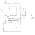
- FIG. 1 shows an example of a system for operating a DC motor application according to the prior art.
- the system according to the invention will be described with reference to FIGS FIG. 1 explained purely by way of example with reference to a radiator fan 1. It is understood that the following explanations are equally applicable to another DC motor application.
- a radiator fan 1 is disposed in an engine compartment 2 of a motor vehicle.
- this engine compartment 2 is an example of a motor 3 and a battery 4.
- the battery 4 may in principle be arranged outside the engine compartment 2.
- a motor application control unit 5 is arranged, so that the radiator fan 1 and the engine application control unit 5 together form a unit.
- the engine application control unit 5 is connected via two lines 7 and 8 for transmitting a supply voltage to the battery 4, wherein the lines for better distinction hereinafter referred to as "power lines” 7 and 8 are called. Furthermore, two lines 9 and 10, hereinafter referred to as “control lines”, connected to an external control unit 11.
- the external control unit 11 is an external signal generator which provides a pulse-width-modulated signal proportional to the setpoint speed of the DC motor to the engine application control unit 5.
- the pulse-width-modulated signal controls the control electronics or the engine application control unit 5 in such a way that the speed of the DC motor in the radiator fan 1 can be continuously controlled or controlled to the desired speed and thus to the desired cooling capacity.
- the speed of the fan motor is so with PWM voltage generated by the engine application control unit 5 is controlled. In the previous solution according to the prior art, the motor is thus controlled or regulated by a pulse width modulated voltage.
- FIG. 1 A disadvantage of the in FIG. 1
- the timing can lead to the formation of harmonics or harmonics with, for example, a multiple of the modulation frequency. These harmonics can cause unwanted side effects such as noise, heating and, above all, electromagnetic compatibility problems.
- the engine application controller must be located near the DC motor application. Like in the FIG. 1 can be seen, they thus form a unity.
- a motor application control unit 5 can thus be assigned to a maximum of a DC motor application.
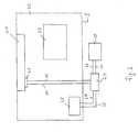
- FIG. 2 shows an embodiment of the system according to the invention for operating a DC motor application for a motor vehicle.
- a radiator fan 21 is disposed in an engine compartment 22 with a motor 23.
- An engine application control unit 24 is located outside the engine compartment 22 in an interior of the motor vehicle.
- the FIG. 2 makes it clear that the control unit 24 and the radiator fan 21 are separated from each other by a usually provided in the vehicle bulkhead S or in other words, the bulkhead S is arranged between them.
- the control unit 24 and the radiator fan 21 thus form, unlike in the prior art, no unit, but are arranged away from each other. This makes it possible, for example, a fan module variation with the same control unit.
- the arrangement of the control device 24 on the protected by the bulkhead S side of the vehicle is also particularly advantageous because the control unit 24 and in particular its line connections or the 4-pin plug thus no longer have to meet the high requirements, for example in terms of tightness.
- the engine application control unit 24 is powered by a arranged in the engine compartment 22 battery 25 via two power lines 26 and 27 with energy.
- a control unit 28 controls the motor application control unit 24 via the control lines 29 and 30 by means of a pulse-width-modulated signal.
- the aforementioned two power lines are preferably connected via a 2-pin connector 33 to the control unit 24.
- FIG. 2 makes it clear that contrary to the system known from the prior art, the engine application control unit 24 in the vicinity of the engine control unit or the control unit 28 and preferably also in the vicinity of the battery 25 is arranged.
- the power lines 26, 27 and the control lines 29, 30 can thus be much shorter, so that a considerable amount of cable can be saved.
- four cables must be routed through the entire engine compartment of the battery and the engine control unit, which is arranged in the interior of the vehicle, to the radiator fan 1 there.
- only two power lines 31 and 32 lead to the radiator fan 21, which transmit a DC voltage generated by the DC / DC converter of the engine application controller 24 to the radiator fan 21 for driving.
- the power lines 31 and 32 are preferably connected to the radiator fan 21 via a 2-pole connector 33.
- the DC / DC converter is preferably multiphase, as in the description FIG. 3 will be explained in more detail.
- the motor application controller 24 need not be placed in the immediate vicinity of the DC motor of the DC motor application, but rather can be arranged in an advantageous manner in the protected interior behind the splash guard S.
- the radiator fan 21 can be made flatter, for example. Due to the flatter construction of the radiator fan 21 and the resulting free space beyond this results in more degrees of freedom in the implementation of pedestrian impact protection measures.
- the engine application controller 24 and the DC motor application are two separate units. This makes it possible to use different variations of DC motor applications with the same motor application controller 24.
- An air output that the radiator fan 21 is to provide is required by a pulse width modulated signal from the control unit 28, in particular from the engine control unit, by the signal via the control lines 29 and 30 is transmitted to the engine application control unit 24.
- the pulse width modulated signal is then evaluated in the motor application control unit 24 and processed to control the DC / DC converter.
- the DC / DC converter then provides an output voltage according to the required signal, which is transmitted to the radiator fan 21 via the power lines 31 and 32.
- FIG. 3 shows a schematic representation of a motor application control unit 24 according to the invention.
- the motor application control unit 24 comprises a multi-phase DC / DC converter 34, which is connected via the power line (KL) 30 to a voltage source, in particular to the battery 25. Between the voltage source and the DC / DC converter 34 may still be connected an EMC filter 35.
- the multi-phase DC / DC converter 34 is connected via lines 31 and 32 to a DC motor application, which in the FIG. 3 not shown.
- a DC motor application which in the FIG. 3 not shown.
- an EMC filter 35 ' can be connected between the polyphase DC / DC converters 34 and the DC motor application, which increases the interference immunity of the system.
- the engine application control unit 24 also has a control unit 36, which in turn comprises a processor 37, which receives a pulse-width-modulated signal from the engine control unit 28, not shown here, via the control line 30.
- the engine controller 28 In order to achieve a desired speed of the DC motor of the DC motor application connected to the engine application controller 24, the engine controller 28 provides a pulse width modulated signal that is proportional to the desired speed. The pulse-width-modulated signal is then evaluated and processed in the processor 37 to drive the multiphase DC / DC converter 34. With the multi-phase DC / DC converter 34, an output voltage is generated according to the signal provided by the engine control unit 28, which is transmitted via the power lines 31 and 32 to the DC motor application.
- a phase of a multi-phase DC / DC converter of the type discussed here comprises switches 38 and 39 and an inductance 40. Each phase also has an input modulator 41 and an output capacitor 42.
- multi-phase DC / DC converters of the type discussed here are made known in the prior art, so it will not be discussed further here. It is crucial that the PWM signal of the engine control unit is processed so that the DC / DC converter can generate a corresponding DC output signal that sets a desired speed and thus a desired cooling performance at the radiator fan 1.
Landscapes
- Engineering & Computer Science (AREA)
- Power Engineering (AREA)
- Mechanical Engineering (AREA)
- Control Of Direct Current Motors (AREA)
- Cooling, Air Intake And Gas Exhaust, And Fuel Tank Arrangements In Propulsion Units (AREA)
Description
- Die vorliegende Erfindung betrifft ein System zum Betreiben einer Gleichstrom-Motorapplikation für ein Kraftfahrzeug, wobei das System eine Gleichstrom-Motorapplikation und ein Motorapplikations-Steuergerät zum Steuern der Gleichstrom-Motorapplikation umfasst. Dabei kommen als Gleichstrom-Motorapplikationen insbesondere ein Kühlerlüfter oder eine Kraftstoffpumpe in Betracht, die beide einen Gleichstrommotor besitzen, um ihre Funktion zu erfüllen.
- Aus der
DE 103 48 130 A1 ist ein Kühlerlüfter einer Kühlanlage für einen Verbrennungsmotor bekannt, der zur Ansteuerung des Lüftermotors eine eigene Steuerelektronik aufweist, die durch das Steuergerät des Antriebsaggregats, d.h. durch das Motorsteuergerät angesteuert wird. Derartige Kühlerlüfter werden auch als Gebläse bezeichnet und weisen Lüfterblätter auf, die von einem Gleichstrommotor angetrieben werden. Zur stufenlosen Steuerung des Kühlerlüfters wird vom Motorsteuergerät ein der Solldrehzahl des Gleichstrommotors proportionales pulsweitenmoduliertes Signal an die Steuerelektronik des Kühlerlüfters weitergeleitet. Weiterhin wird der Steuerelektronik des Kühlerlüfters eine Versorgungsspannung vom Bordnetz, insbesondere von der Fahrzeugbatterie zugeführt. Die Steuerelektronik von herkömmlichen Kühlerlüftermotoren ist im frontendseitigen Bereich des Motorraums in unmittelbarer Nähe zum Kühlerlüfter angeordnet, da die Steuerelektronik über eine getaktete Leitung, auch getaktete "Powerleitung" genannt, mit dem Gleichstrommotor des Kühlerlüfters verbunden ist. Diese Leitung sollte so kurz wie möglich sein, um EMV-Probleme (EMV = elektromagnetische Verträglichkeit) so gering wie möglich zu halten. Die Steuerelektronik und der Kühlerlüftermotor bilden somit eine Einheit. Durch die Taktung kann es nämlich zur Bildung von Oberschwingungen bzw. Oberwellen kommen, die zu unerwünschten Nebeneffekten wie Geräuschbildung, Erwärmung und den oben angesprochenen Problemen mit der elektromagnetischen Verträglichkeit führen können. Ein weiteres Problem herkömmlicher Kühlanlagen ist es, dass der Kühlerlüfter und seine Steuerelektronik in der Regel im Frontendbereich des Motorraums angeordnet sind, wo Platzmangel herrscht. - Die oben beispielhaft für Kühlanlagen dargestellten Probleme ergeben sich gleichermaßen für andere Gleichstrommotor betriebene Anwendungen, wie beispielsweise für die Kraftstoffpumpe oder dergleichen.
- Der vorliegenden Erfindung liegt daher die Aufgabe zugrunde, ein System zum Betreiben einer Gleichstrom-Motorapplikation für ein Kraftfahrzeug bereitzustellen, welches es ermöglicht, die Drehzahl des Gleichstrommotors der Gleichstrom-Motorapplikation stufenlos zu regeln, und welches dabei im eingebauten Zustand im Vergleich zum Stand der Technik Platzprobleme im Motorraum vermeidet.
-
DE 10 2007 050 083 A1 beschreibt ein System gemäß dem Oberbegriff des Anspruchs 1. - Diese Aufgabe wird gelöst durch ein System mit den Merkmalen des Anspruchs 1. Bevorzugte Ausführungsformen sind in den abhängigen Ansprüchen angegeben.
- Die Erfindung umfasst ein System zum Betreiben einer Gleichstrom-Motorapplikation für ein Kraftfahrzeug, wobei das System wenigstens eine Gleichstrom-Motorapplikation und ein Motorapplikations-Steuergerät bzw. eine Steuerelektronik zum Steuern der wenigstens einen Gleichstrom-Motorapplikation umfasst. Erfindungsgemäß ist das Motorapplikations-Steuergerät von der Gleichstrom-Motorapplikation entfernt angeordnet. Im Gegensatz zu aus dem Stand der Technik bekannten Systemen ist das Motorapplikations-Steuergerät also von der Gleichstrom-Motorapplikation entkoppelt, d.h. es ist nicht in unmittelbarer Nähe zu dem Gleichstrommotor der jeweiligen Anwendung angeordnet. Dies wird dadurch ermöglicht, dass die Steuerelektronik erfindungsgemäß einen DC/DC-Wandler zur Ansteuerung wenigstens einer Gleichstrom-Motorapplikation mittels einer Gleichspannung aufweist. Bei einer Gleichstrom-Motorapplikation kann es sich, wie eingangs erläutert, beispielsweise um einen Kühlerlüfter handeln, der einen Lüfterblätter antreibenden Gleichstrommotor umfasst.
- Ein wesentlicher Punkt der Erfindung liegt darin, dass die vorteilhafte entfernte Anordnung des Motorapplikations-Steuergeräts und der Gleichstrom-Motorapplikation die Platzprobleme im Motorraum, insbesondere im Frontendbereich des Motorraums vermeidet. Die Probleme, die mit einer derartigen entfernten Anordnung eines Motorapplikations-Steuergeräts bei einer aus dem Stand der Technik bekannten Gleichstrom-Motorapplikation einhergehen, werden durch den Einsatz eines DC/DC-Wandlers in der Steuerelektronik vermieden, weil EMV-Probleme durch das resultierende Ansteuerverfahren mittels einer Gleichspannung weitgehend ausgeräumt werden können. Durch den vorteilhaften Einsatz eines DC/DC-Wandlers kann das Motorapplikations-Steuergerät somit entfernt von der zugeordneten Gleichstrom-Motorapplikation bzw. von den zugeordneten Gleichstrom-Motorapplikationen angeordnet werden.
- Weitere Vorteile der Erfindung liegen in der einfachen Drehzahlsteuerung einer oder mehrerer Gleichstrom-Motorapplikationen durch die Variation der Motorspannung, die durch den DC/DC-Wandler erzeugt wird. Dadurch, dass durch den Einsatz eines DC/DC-Wandlers die Möglichkeit einer entfernten Anordnung des Motorapplikations-Steuergeräts von einer Gleichstrom-Motorapplikation eröffnet wird, können auch mehrere gleiche oder unterschiedliche Gleichstrom-Motorapplikationen durch ein einziges Motorapplikations-Steuergerät angesteuert werden. Verschiedene Gleichstrom-Motorapplikationen können dabei wiederum entfernt voneinander angeordnet sein. Weiterhin sind durch die Verwendung eines DC/DC-Wandlers zur Leistungsversorgung des Gleichstrommotors ein weicher Anlauf und ein weicher Wechsel der Gleichstrommotordrehzahl realisierbar. Darüber hinaus lässt sich eine Überspannungsschutzeinrichtung realisieren, welche also eine Begrenzung der Ausgangsspannung des Motorapplikations-Steuergeräts bewirkt und somit die angeschlossenen Gleichstrommotoren vor einer Überspannung schützt.
- Das System gemäß der Erfindung erlaubt es im Übrigen die Funktion der angeschlossenen Gleichstrom-Motorapplikation selbstständig zu überwachen. Insbesondere kann die Funktion in Hinblick auf eine Kurzschlusserkennung, eine Blockade, eine Überlastung bzw. Schwergängigkeit oder auf einen Abriss hin, d.h. eine Unterbrechung der Last-Leitung überwacht werden. Weiterhin ist eine Spannungsüberwachung möglich.
- Das System umfasst vorzugsweise einen externen Signalgeber, der das Motorapplikations-Steuergerät mit einem pulsweitenmodulierten Signal speist. Dabei handelt es sich insbesondere um das Motorsteuergerät. Das pulsweitenmodulierte Signal (PWM-Signal) wird dann in dem Motorapplikations-Steuergerät ausgewertet und zur Ansteuerung des DC/DC-Wandlers aufbereitet. Über die PWM-Verbindungsleitung zwischen dem Motorsteuergerät und dem Motorapplikations-Steuergerät kann darüber hinaus eine Fehlerrückmeldung an das Motorsteuergerät erfolgen.
- Der DC/DC-Wandler ist vorzugsweise als sogenannter "Multi Phase Controller", im Folgenden "MPC" genannt, ausgebildet. Die Verwendung eines mehrphasigen DC/DC-Wandlers ist dabei besonders vorteilhaft, weil durch die mehrere Phasen des DC/DC-Wandlers Spannungs- und Stromripple und die Eingangs- und Ausgangsripple reduziert werden, wodurch das EMV-Verhalten des Systems verbessert wird. Die geringeren ohmschen Verluste mehrphasiger Schaltungstopologien verbessern im Übrigen den Wirkungsgrad des Systems. Darüber hinaus tragen kleinere Bauteile, die weniger Leistung benötigen, zu einem kompakten Design bei. Die Verlustleistung kann weiterhin auf mehrere Bauteile verteilt werden. Insgesamt wird dadurch auch der benötigte Kühlaufwand der Steuerelektronik reduziert, da die Wärmeabfuhr verbessert wird.
- In einer Ausführungsform sind die Gleichstrom-Motorapplikationen innerhalb eines Motorraums eines Kraftfahrzeugs anordnungsfähig und das Motorapplikations-Steuergerät außerhalb des Motorraums anordnungsfähig. Dadurch muss sich das Motorapplikations-Steuergerät nicht mehr innerhalb des Motorraums in der Nähe der Gleichstrom-Motorapplikation befinden, wodurch im Motorraum Platz gespart werden kann.
- Bei der Erfindung ist das Motorapplikations-Steuergerät über sogenannte Powerleitungen zur Übertragung der durch den DC/DC-Wandler erzeugten Gleichspannung an den Gleichstrommotor mit der Gleichstrom-Motorapplikation verbunden. Im Vergleich zum Stand der Technik führen daher weniger Leitungen durch den Motorraum zur jeweiligen Gleichstrom-Motorapplikation.
- In einer vorteilhaften Ausführungsform sind die zwei Leitungen über einen zweipoligen Stecker mit der Gleichstrom-Motorapplikation verbunden. Grundsätzlich denkbar ist jedoch auch jede andere Art der Verbindung möglich. Denkbar ist es beispielsweise die Leitungen zu schweißen oder zu krimpen.
- Die Gleichstrom-Motorapplikation kann insbesondere ein Kühlerlüfter oder eine Kraftstoffpumpe sein.
- Die Erfindung wird im Folgenden anhand der Zeichnung näher erläutert. Es zeigen:
- Figur 1
- ein System zum Betreiben einer Gleichstrom-Motorapplikation (insbesondere eines Kühlerlüfters) nach dem Stand der Technik;
- Figur 2
- eine Ausführungsform des erfindungsgemäßen Systems zum Betreiben einer Gleichstrom-Motorapplikation, und
- Figur 3
- eine schematische Darstellung eines Motorapplikations-Steuergeräts.
-
Figur 1 zeigt ein Beispiel für ein System zum Betreiben einer Gleichstrom-Motorapplikation nach dem Stand der Technik. Das System gemäß der Erfindung wird mit Bezug auf dieFigur 1 rein beispielhaft anhand eines Kühlerlüfters 1 erläutert. Es versteht sich, dass die nachfolgenden Erläuterungen gleichermaßen auf eine andere Gleichstrom-Motorapplikation übertragbar sind. - In dem System ist ein Kühlerlüfter 1 in einem Motorraum 2 eines Kraftfahrzeugs angeordnet. In diesem Motorraum 2 befindet sich beispielhaft ein Motor 3 und eine Batterie 4. Die Batterie 4 kann grundsätzlich auch außerhalb des Motorraums 2 angeordnet sein. Am Kühlerlüfter 1 ist ein Motorapplikations-Steuergerät 5 angeordnet, sodass der Kühlerlüfter 1 und das Motorapplikations-Steuergerät 5 zusammen eine Einheit bilden.
- Mittels eines vierpoligen Steckers 6 ist das Motorapplikations-Steuergerät 5 über zwei Leitungen 7 und 8 zur Übertragung einer Versorgungsspannung mit der Batterie 4 verbunden, wobei die Leitungen zur besseren Unterscheidung im Folgenden als "Powerleitungen" 7 und 8 bezeichnet werden. Weiterhin sind zwei Leitungen 9 und 10, im Folgenden als "Steuerleitungen" bezeichnet, mit einer externen Steuereinheit 11 verbunden. Bei der externen Steuereinheit 11 handelt es sich um einen externen Signalgeber, der ein der Solldrehzahl des Gleichstrommotors proportionales pulsweitenmoduliertes Signal an dem Motorapplikations-Steuergerät 5 bereitstellt. Das pulsweitenmodulierte Signal steuert die Steuerungselektronik bzw. das Motorapplikations-Steuergerät 5 derart an, dass die Drehzahl des Gleichstrommotors im Kühlerlüfter 1 stufenlos auf die gewünschte Drehzahl und damit auf die gewünschte Kühlleistung geregelt bzw. gesteuert werden kann. Die Drehzahl des Lüftermotors wird also mit PWM-Spannung, die von dem Motorapplikations-Steuergerät 5 erzeugt wird, geregelt bzw. gesteuert. Bei der bisherigen Lösung nach dem Stand der Technik wird der Motor also durch eine pulsweitenmodulierte Spannung gesteuert bzw. geregelt.
- Nachteilig an dem in
Figur 1 gezeigten System gemäß dem Stand der Technik ist, dass sich das Motorapplikations-Steuergerät 5 im Motorraum 2 befindet, da in den heutigen Motorräumen von Kraftfahrzeugen Platzmangel herrscht. Daher ist es erstrebenswert das Motorapplikations-Steuergerät außerhalb des Motorraums anzuordnen. Bei Systemen nach dem Stand der Technik gehen damit jedoch inakzeptable Probleme mit der Leistungsübertragung an die Gleichstrom-Motorapplikation einher. Insbesondere ist dann eine Abschirmung der Powerleitungen von dem Motorapplikations-Steuergerät 5 zu dem Kühlerlüfter 1 notwendig, da durch die elektromagnetischen Einflüsse der getakteten Leitung ansonsten andere elektrische Elemente wie Parksensoren, Infotainment oder dergleichen in ihrer Funktion gestört werden können. Der Grund hierfür ist, dass durch die herkömmlichen Motorapplikations-Steuergeräte eine getaktete Leistung erzeugt wird, die an den Kühlerlüfter 1 übertragen wird. Durch die Taktung kann es zur Bildung von Oberschwingungen bzw. Oberwellen kommen mit z.B. einem Vielfachen der Modulationsfrequenz. Durch diese Oberschwingungen können unerwünschte Nebeneffekte wie Geräuschbildung, Erwärmung und vor allem Probleme mit elektromagnetischer Verträglichkeit entstehen. Um diese Nebeneffekte zu minimieren, muss das Motorapplikations-Steuergerät in der Nähe der Gleichstrom-Motorapplikation angeordnet sein. Wie in derFigur 1 ersichtlich ist, bilden diese somit eine Einheit. Ein Motorapplikations-Steuergerät 5 ist damit maximal einer Gleichstrom-Motorapplikation zuordenbar. -
Figur 2 zeigt eine Ausführungsform des erfindungsgemäßen Systems zum Betreiben einer Gleichstrom-Motorapplikation für ein Kraftfahrzeug. In der Ausführungsform des Systems ist ein Kühlerlüfter 21 in einem Motorraum 22 mit einem Motor 23 angeordnet. Ein Motorapplikations-Steuergerät 24 befindet sich außerhalb des Motorraums 22 in einem Innenraum des Kraftfahrzeugs. DieFigur 2 macht deutlich, dass das Steuergerät 24 und der Kühlerlüfter 21 durch eine üblicherweise im Fahrzeug vorgesehene Spritzwand S voneinander getrennt sind oder anders ausgedrückt ist die Spritzwand S zwischen ihnen angeordnet. Das Steuergerät 24 und der Kühlerlüfter 21 bilden damit anders als im Stand der Technik keine Einheit, sondern sind entfernt voneinander angeordnet. Hierdurch ist beispielweise eine Lüftermodulvariation bei gleichbleibendem Steuergerät möglich. Die Anordnung des Steuergeräts 24 auf der durch die Spritzwand S geschützten Seite des Fahrzeugs ist darüber hinaus besonders vorteilhaft, weil das Steuergerät 24 und insbesondere seine Leitungsanschlüsse bzw. der 4-polige Stecker hierdurch nicht mehr die hohen Anforderungen beispielsweise in Bezug auf die Dichtigkeit erfüllen müssen. - Das Motorapplikations-Steuergerät 24 wird von einer im Motorraum 22 angeordneten Batterie 25 über zwei Powerleitungen 26 und 27 mit Energie versorgt. Eine Steuereinheit 28 steuert über die Steuerleitungen 29 und 30 das Motorapplikations-Steuergerät 24 mittels eines pulsweitenmodulierten Signals an. Die vorgenannten zwei Powerleitungen sind vorzugsweise über einen 2-poligen Stecker 33 mit dem Steuergerät 24 verbunden.
- Die
Figur 2 macht deutlich, dass entgegen dem aus dem Stand der Technik bekannten System das Motorapplikations-Steuergerät 24 in der Nähe des Motorsteuergeräts bzw. der Steuereinheit 28 und vorzugsweise auch in der Nähe der Batterie 25 angeordnet ist. Die Powerleitungen 26, 27 und die Steuerleitungen 29, 30 können damit wesentlich kürzer sein, sodass eine nicht unerhebliche Kabelmenge eingespart werden kann. Wie im Vergleich zu derFigur 1 deutlich wird, müssen dort vier Kabel durch den gesamten Motorraum von der Batterie und vom Motorsteuergerät, welches im Innenraum des Fahrzeugs angeordnet ist, zu dem Kühlerlüfter 1 geführt werden. Im Gegensatz dazu führen von dem entfernt angeordneten Motorapplikations-Steuergerät 24 nur noch zwei Powerleitungen 31 und 32 zu dem Kühlerlüfter 21, die eine durch den DC/DC-Wandler des Motorapplikations-Steuergeräts 24 erzeugte Gleichspannung zur Ansteuerung an den Kühlerlüfter 21 übertragen. Die Powerleitungen 31 und 32 sind vorzugsweise über einen 2-poligen Stecker 33 mit dem Kühlerlüfter 21 verbunden. - Der DC/DC-Wandler ist vorzugsweise mehrphasig ausgebildet, wie in der Beschreibung zu
Figur 3 noch näher erläutert wird. Durch die vorteilhafte Ansteuerung des Kühlerlüfters 21 mittels einer durch den DC/DC-Wandler erzeugten Gleichspannung können zum einen mehrere Gleichstrom-Motorapplikationen durch ein einziges Steuergerät 24 betrieben werden und darüber hinaus müssen die die Gleichspannung übertragenden Powerleitungen 31 und 32 nicht abgeschirmt werden, weil die übertragene Gleichspannung verbesserte EMV-Eigenschaften aufweist, sodass Parksensoren oder andere elektronische Einheiten des Fahrzeugs nicht negativ beeinflusst werden. - Durch den Einsatz eines DC/DC-Wandlers und insbesondere eines mehrphasigen DC/DC-Wandlers muss das Motorapplikations-Steuergerät 24 nicht in unmittelbarer Nähe des Gleichstrommotors der Gleichstrom-Motorapplikation platziert werden, sondern kann in vorteilhafter Weise im geschützten Innenraum hinter dem Spritzschutz S angeordnet werden. In der in
Figur 2 gezeigten Ausführungsform kann dadurch der Kühlerlüfter 21 z.B. flacher aufgebaut werden. Durch die flachere Aufbauweise des Kühlerlüfters 21 und der hierdurch resultierende Freiraum ergeben sich darüber hinaus mehr Freiheitsgrade bei der Umsetzung von Fußgänger-Aufprallschutzmaßnahmen. Gemäß der Erfindung sind das Motorapplikations-Steuergerät 24 und die Gleichstrom-Motorapplikation zwei separate Einheiten. Dies ermöglicht es, unterschiedliche Variationen von Gleichstrom-Motorapplikationen mit demselben Motorapplikations-Steuergerät 24 zu verwenden. - Im Folgenden wird kurz auf die Funktionsweise des Systems nach
Figur 2 eingegangen. Eine Luftleistung, die der Kühlerlüfter 21 erbringen soll, wird durch ein pulsweitenmoduliertes Signal von der Steuereinheit 28, insbesondere von dem Motorsteuergerät gefordert, indem das Signal über die Steuerleitungen 29 und 30 an das Motorapplikations-Steuergerät 24 übertragen wird. Das pulsweitenmodulierte Signal wird daraufhin in dem Motorapplikations-Steuergerät 24 ausgewertet und zur Ansteuerung des DC/DC-Wandlers aufbereitet. Der DC/DC-Wandler stellt dann entsprechend dem geforderten Signal eine Ausgangsspannung bereit, die über die Powerleitungen 31 und 32 an den Kühlerlüfter 21 übertragen wird. -
Figur 3 zeigt eine schematische Darstellung eines Motorapplikations-Steuergeräts 24 gemäß der Erfindung. Das Motorapplikations-Steuergerät 24 umfasst einen mehrphasigen DC/DC-Wandler 34, der über die Powerleitung (KL)30 an eine Spannungsquelle, insbesondere an die Batterie 25 angeschlossen ist. Zwischen die Spannungsquelle und den DC/DC-Wandler 34 kann noch ein EMV-Filter 35 geschaltet sein. - Der mehrphasige DC/DC-Wandler 34 ist über die Leitungen 31 und 32 mit einer Gleichstrom-Motorapplikation verbunden, die In der
Figur 3 nicht dargestellt ist. Alternativ oder auch zusätzlich zu dem EMV-Filter 35 kann zwischen den mehrphasigen DC/DC-Wandler 34 und die Gleichstrom-Motorapplikation ein EMV-Filter 35' geschaltet sein, welches die Störfestigkeit des Systems erhöht. - Es sei an dieser Stelle erwähnt, dass grundsätzlich auch der Einsatz eines serienresonanten mehrphasigen DC/DC-Wandlers oder auch eines herkömmlichen einphasigen DC/DC-Wandlers denkbar ist. Besonders vorteilhaft ist der Einsatz eines dreiphasigen DC/DC-Wandlers mit drei Phasen 34a, 34b und 34c, wie er in
Figur 3 dargestellt ist. - Das Motorapplikations-Steuergerät 24 weist außerdem eine Steuereinheit 36 auf, die wiederum einen Prozessor 37 umfasst, der über die Steuerleitung 30 ein pulsweitenmoduliertes Signal von der hier nicht dargestellten Motorsteuereinheit 28 erhält.
- Um eine gewünschte Drehzahl des Gleichstrommotors der an das Motorapplikations-Steuergerät 24 angeschlossenen Gleichstrom-Motorapplikation herbeizuführen, gibt das Motorsteuergerät 28 ein pulsweitenmoduliertes Signal vor, das proportional zu der gewünschten Drehzahl ist. Das pulsweitenmodulierte Signal wird dann ausgewertet und zur Ansteuerung des mehrphasigen DC/DC-Wandlers 34 in dem Prozessor 37 aufbereitet. Mit dem mehrphasigen DC/DC-Wandler 34 wird entsprechend dem durch das Motorsteuergerät 28 bereitgestellten Signal eine Ausgangsspannung erzeugt, die über die Powerleitungen 31 und 32 an die Gleichstrom-Motorapplikation übertragen wird.
- Eine Phase eines mehrphasigen DC/DC-Wandlers der hier angesprochenen Art umfasst Schalter 38 und 39 sowie eine Induktivität 40. Jede Phase weist darüber hinaus einen Eingangskodensator 41 und einen Ausgangskondensator 42. Im Übrigen sind mehrphasige DC/DC-Wandler der hier angesprochenen Art aus dem Stand der Technik bekannt, sodass hier nicht näher darauf eingegangen werden soll. Entscheidend ist, dass das PWM-Signal des Motorsteuergeräts so aufgearbeitet wird, dass der DC/DC-Wandler ein entsprechendes Gleichspannungsausgangssignal erzeugen kann, das an dem Kühlerlüfter 1 eine gewünschte Drehzahl und damit eine gewünschte Kühlleistung einstellt.
-
- 1
- Kühlerlüfter (Gleichstrom-Motorapplikation)
- 2
- Motorraum
- 3
- Motor
- 4
- Batterie
- 5
- Motorapplikations-Steuergerät
- 6
- vierpoliger Stecker
- 7
- Leitung
- 8
- Leitung
- 9
- Leitung
- 10
- Leitung
- 11
- Steuereinheit
- 21
- Gleichstrom-Motorapplikation (Kühlerlüfter)
- 22
- Motorraum
- 23
- Motor
- 24
- Motorapplikations-Steuergerät (Steuerelektronik)
- 25
- Batterie
- 26
- Powerleitung
- 27
- Powerleitung
- 28
- Steuereinheit (Motorsteuergerät)
- 29
- Steuerleitung
- 30
- Steuerleitung
- 31
- Powerleitung
- 32
- Powerleitung
- 33
- 2-poliger Stecker
- 34
- mehrphasiger DC/DC-Wandler
- 34a
- Phase 1
- 34b
- Phase 2
- 34c
- Phase 3
- 35
- EMV-Filter
- 35'
- EMV-Filter
- 36
- Steuereinheit
- 37
- Prozessor
- 38
- Schalter
- 39
- Schalter
- 40
- Induktivität
- 41
- Eingangskondensator
- 42
- Ausgangskondensator
- S
- Spritzschutz
Claims (15)
- System zum Betreiben einer Gleichstrom-Motorapplikation (21) für ein Kraftfahrzeug, umfassend- wenigstens eine Gleichstrom-Motorapplikation (21) und- ein Motorapplikations-Steuergerät (24) zum Steuern der wenigstens einen Gleichstrom-Motorapplikation (21),dadurch gekennzeichnet, dass
das Motorapplikations-Steuergerät (24) von der Gleichstrom-Motorapplikation (21) entfernt angeordnet ist und einen DC-DC-Wandler (34) zur Ansteuerung wenigstens einer Gleichstrom-Motorapplikation (21) über Powerleitungen mittels einer Gleichspannung aufweist. - System nach Anspruch 1, wobei die Gleichstrom-Motorapplikation (21) innerhalb eines Motorraums (22) eines Kraftfahrzeugs anordnungsfähig und das Motorapplikations-Steuergerät (24) außerhalb des Motorraums (22) anordnungsfähig ist.
- System nach Anspruch 1 oder 2, wobei das Motorapplikations-Steuergerät (24) über zwei Leitungen (31, 32) mit der Gleichstrom-Motorapplikation (21) verbunden ist.
- System nach Anspruch 3, wobei die zwei Leitungen (31, 32) über einen zweipoligen Stecker (33) mit der Gleichstrom-Motorapplikation (21) verbunden sind.
- System nach einem der Ansprüche 1 bis 4, wobei die Gleichstrom-Motorapplikation (21) ein Kühlerlüfter ist.
- System nach einem der Ansprüche 1 bis 4, wobei die Gleichstrom-Motorapplikation (21) eine Kraftstoffpumpe ist.
- System nach einem der vorhergehenden Ansprüche, wobei der DC/DC-Wandler ein mehrphasiger DC/DC-Wandler ist.
- System nach Anspruch 7, wobei der mehrphasiger DC/DC-Wandler drei Phasen aufweist.
- System nach Anspruch 7 oder 8, wobei der mehrphasige DC/DC-Wandler eingangs- und/oder ausgangsseitig einen EMV-Filter aufweist.
- System nach einem der vorhergehenden Ansprüche, wobei zwischen der Gleichstrom-Motorapplikation (21) und dem Motorapplikations-Steuergerät (24) eine Spritzwand (S) angeordnet ist.
- System nach Anspruch 10, wobei die Gleichstrom-Motorapplikation (21) auf der Motorraumseite der Spritzwand (S) und das Motorapplikations-Steuergerät (24) auf der Innenraumseite der Spritzwand (S) anordenbar sind.
- System nach einem der vorhergehenden Ansprüche, umfassend einen externen Signalgeber (28), der das Motorapplikations-Steuergerät (24) mit einem pulsweitenmodulierten Signal speist.
- System nach Anspruch 12, wobei es sich bei dem externen Signalgeber (28) um das Motorsteuergerät handelt.
- System nach Anspruch 12 oder 13, wobei das pulsweitenmodulierte Signal in dem Motorapplikations-Steuergerät (24) ausgewertet und zur Ansteuerung des DC/DC-Wandlers aufbereitet wird.
- Motorapplikations-Steuergerät (24), aufweisend einen DC/DC-Wandler zur Verwendung in einem System nach einem der vorhergehenden Ansprüche.
Priority Applications (2)
| Application Number | Priority Date | Filing Date | Title |
|---|---|---|---|
| ES10168261.5T ES2495767T3 (es) | 2010-07-02 | 2010-07-02 | Sistema para la operación de una aplicación de motor de corriente continua para un automóvil |
| EP10168261.5A EP2402182B1 (de) | 2010-07-02 | 2010-07-02 | System zum Betreiben einer Gleichstrom-Motorapplikation für ein Kraftfahrzeug |
Applications Claiming Priority (1)
| Application Number | Priority Date | Filing Date | Title |
|---|---|---|---|
| EP10168261.5A EP2402182B1 (de) | 2010-07-02 | 2010-07-02 | System zum Betreiben einer Gleichstrom-Motorapplikation für ein Kraftfahrzeug |
Publications (2)
| Publication Number | Publication Date |
|---|---|
| EP2402182A1 EP2402182A1 (de) | 2012-01-04 |
| EP2402182B1 true EP2402182B1 (de) | 2014-06-04 |
Family
ID=42338284
Family Applications (1)
| Application Number | Title | Priority Date | Filing Date |
|---|---|---|---|
| EP10168261.5A Not-in-force EP2402182B1 (de) | 2010-07-02 | 2010-07-02 | System zum Betreiben einer Gleichstrom-Motorapplikation für ein Kraftfahrzeug |
Country Status (2)
| Country | Link |
|---|---|
| EP (1) | EP2402182B1 (de) |
| ES (1) | ES2495767T3 (de) |
Families Citing this family (1)
| Publication number | Priority date | Publication date | Assignee | Title |
|---|---|---|---|---|
| CN104518711A (zh) * | 2013-09-30 | 2015-04-15 | 贵州航天电子科技有限公司 | 基于编码技术的电机无级调速电路 |
Family Cites Families (6)
| Publication number | Priority date | Publication date | Assignee | Title |
|---|---|---|---|---|
| JP3776348B2 (ja) * | 2001-12-10 | 2006-05-17 | 本田技研工業株式会社 | 車両用電源装置 |
| DE10348130A1 (de) | 2003-10-16 | 2005-05-12 | Daimler Chrysler Ag | Kühlanlage für einen Verbrennungsmotor eines Kraftfahrzeugs |
| JP2006002631A (ja) * | 2004-06-16 | 2006-01-05 | Toyota Motor Corp | 熱交換装置およびこれを搭載するハイブリッド車。 |
| DE102004036814B4 (de) * | 2004-07-29 | 2006-06-01 | Siemens Ag | Vorrichtung zur Versorgung einer Kraftstoffpumpe einer Brennkraftmaschine eines Kraftfahrzeuges mit elektrischem Strom |
| US20090095462A1 (en) * | 2007-10-12 | 2009-04-16 | Ford Global Technologies, Llc | Method and system for controlling cooling fans in a vehicle |
| DE102007050083A1 (de) * | 2007-10-19 | 2009-04-23 | Dr. Ing. H.C. F. Porsche Aktiengesellschaft | Verfahren zur Kühlung von Steuergeräten in Kraftfahrzeugen |
-
2010
- 2010-07-02 EP EP10168261.5A patent/EP2402182B1/de not_active Not-in-force
- 2010-07-02 ES ES10168261.5T patent/ES2495767T3/es active Active
Also Published As
| Publication number | Publication date |
|---|---|
| ES2495767T3 (es) | 2014-09-17 |
| EP2402182A1 (de) | 2012-01-04 |
Similar Documents
| Publication | Publication Date | Title |
|---|---|---|
| DE60119039T2 (de) | Halbleitervorrichtung, Stromwandler und Fahrzeug | |
| DE102013112147B4 (de) | Schaltungsanordnungen und verfahren zum betreiben einer elektromaschine | |
| DE112015001689T5 (de) | Fahrzeugantriebsvorrichtung | |
| DE102022127899A1 (de) | Elektrische Antriebsvorrichtung für den elektrischen Antrieb einer Autobetonpumpe, Autobetonpumpe und System zum Antrieb einer Autobetonpumpe | |
| DE102020118904A1 (de) | Bordseitiger wechselstromgenerator für power-to-the-box in fahrzeugen mit einer brennkraftmaschine | |
| DE102019204927A1 (de) | Antriebsvorrichtung | |
| DE102021133267A1 (de) | Elektrischer Antrieb eines Fahrzeuges | |
| EP3132967A1 (de) | Ladegerät zum laden der traktionsbatterie eines elektrofahrzeugs und elektrofahrzeug | |
| EP1866540B1 (de) | Schalteinrichtung zur verknüpfung verschiedener elektrischer spannungsebenen in einem kraftfahrzeug | |
| DE102007005571A1 (de) | Lüfteranordnung mit erhöhter Verfügbarkeit und Verfahren zu ihrem Betrieb | |
| EP2402182B1 (de) | System zum Betreiben einer Gleichstrom-Motorapplikation für ein Kraftfahrzeug | |
| DE102015013062A1 (de) | Elektrisches System für ein Brennstoffzellenfahrzeug | |
| EP4551813A1 (de) | Elektrische antriebsvorrichtung für den elektrischen antrieb einer autobetonpumpe, autobetonpumpe und system zum antrieb einer autobetonpumpe | |
| DE10318172B4 (de) | Elektrisches Bordnetz mit Brennstoffzelle und Verfahren zum Betreiben eines elektrischen Verbrauchers in einem solchen Bordnetz | |
| EP0925993B1 (de) | Elektrische Bremswiderstandsbaueinheit für elektrische Antriebssysteme | |
| DE102019202345B4 (de) | Fahrzeugbordnetz mit einem Akkumulator, einem Wechselspannungsanschluss und einem Gleichspannungsanschluss | |
| WO2011039166A1 (de) | Kreiselpumpenaggregat mit schaltvorrichtung | |
| EP3256347B1 (de) | Verfahren zur steuerung eines verbrauchers eines niedervoltbordnetzes | |
| DE102008041236A1 (de) | Verfahren zum Betreiben einer Antriebsvorrichtung, Antriebsvorrichtung und Mehrfachlüfteranordnung | |
| EP1636059B1 (de) | Feuerwehrlöschfahrzeug mit einem antriebssystem, sowie verfahren zur steuerung des antriebssystems | |
| EP3053257B1 (de) | Gleichspannungswandler und verfahren zum ansteuern eines gleichspannungswandlers | |
| DE102004002105B3 (de) | KFZ-Kraftstoffpumpe | |
| EP3300204B1 (de) | Hochvolt-kraftfahrzeugbordnetz | |
| EP3723268B1 (de) | Komponentenintegrierte schnittstelle | |
| DE102009001507A1 (de) | Verfahren zum Betrieb eines elektrischen Servolenksystems und danach arbeitendes Steuergerät |
Legal Events
| Date | Code | Title | Description |
|---|---|---|---|
| AK | Designated contracting states |
Kind code of ref document: A1 Designated state(s): AL AT BE BG CH CY CZ DE DK EE ES FI FR GB GR HR HU IE IS IT LI LT LU LV MC MK MT NL NO PL PT RO SE SI SK SM TR |
|
| AX | Request for extension of the european patent |
Extension state: BA ME RS |
|
| PUAI | Public reference made under article 153(3) epc to a published international application that has entered the european phase |
Free format text: ORIGINAL CODE: 0009012 |
|
| 17P | Request for examination filed |
Effective date: 20120203 |
|
| GRAP | Despatch of communication of intention to grant a patent |
Free format text: ORIGINAL CODE: EPIDOSNIGR1 |
|
| RIC1 | Information provided on ipc code assigned before grant |
Ipc: B60H 1/00 20060101AFI20131115BHEP Ipc: H02J 7/00 20060101ALI20131115BHEP Ipc: H02P 6/08 20060101ALI20131115BHEP Ipc: B60R 16/03 20060101ALI20131115BHEP |
|
| INTG | Intention to grant announced |
Effective date: 20131212 |
|
| GRAS | Grant fee paid |
Free format text: ORIGINAL CODE: EPIDOSNIGR3 |
|
| GRAA | (expected) grant |
Free format text: ORIGINAL CODE: 0009210 |
|
| AK | Designated contracting states |
Kind code of ref document: B1 Designated state(s): AL AT BE BG CH CY CZ DE DK EE ES FI FR GB GR HR HU IE IS IT LI LT LU LV MC MK MT NL NO PL PT RO SE SI SK SM TR |
|
| REG | Reference to a national code |
Ref country code: GB Ref legal event code: FG4D Free format text: NOT ENGLISH |
|
| REG | Reference to a national code |
Ref country code: CH Ref legal event code: EP |
|
| REG | Reference to a national code |
Ref country code: AT Ref legal event code: REF Ref document number: 670871 Country of ref document: AT Kind code of ref document: T Effective date: 20140615 |
|
| REG | Reference to a national code |
Ref country code: IE Ref legal event code: FG4D Free format text: LANGUAGE OF EP DOCUMENT: GERMAN |
|
| REG | Reference to a national code |
Ref country code: DE Ref legal event code: R096 Ref document number: 502010007098 Country of ref document: DE Effective date: 20140717 |
|
| REG | Reference to a national code |
Ref country code: SE Ref legal event code: TRGR |
|
| REG | Reference to a national code |
Ref country code: ES Ref legal event code: FG2A Ref document number: 2495767 Country of ref document: ES Kind code of ref document: T3 Effective date: 20140917 |
|
| REG | Reference to a national code |
Ref country code: NL Ref legal event code: VDEP Effective date: 20140604 |
|
| PG25 | Lapsed in a contracting state [announced via postgrant information from national office to epo] |
Ref country code: LT Free format text: LAPSE BECAUSE OF FAILURE TO SUBMIT A TRANSLATION OF THE DESCRIPTION OR TO PAY THE FEE WITHIN THE PRESCRIBED TIME-LIMIT Effective date: 20140604 Ref country code: CY Free format text: LAPSE BECAUSE OF FAILURE TO SUBMIT A TRANSLATION OF THE DESCRIPTION OR TO PAY THE FEE WITHIN THE PRESCRIBED TIME-LIMIT Effective date: 20140604 Ref country code: NO Free format text: LAPSE BECAUSE OF FAILURE TO SUBMIT A TRANSLATION OF THE DESCRIPTION OR TO PAY THE FEE WITHIN THE PRESCRIBED TIME-LIMIT Effective date: 20140904 Ref country code: GR Free format text: LAPSE BECAUSE OF FAILURE TO SUBMIT A TRANSLATION OF THE DESCRIPTION OR TO PAY THE FEE WITHIN THE PRESCRIBED TIME-LIMIT Effective date: 20140905 Ref country code: FI Free format text: LAPSE BECAUSE OF FAILURE TO SUBMIT A TRANSLATION OF THE DESCRIPTION OR TO PAY THE FEE WITHIN THE PRESCRIBED TIME-LIMIT Effective date: 20140604 |
|
| REG | Reference to a national code |
Ref country code: LT Ref legal event code: MG4D |
|
| PG25 | Lapsed in a contracting state [announced via postgrant information from national office to epo] |
Ref country code: LV Free format text: LAPSE BECAUSE OF FAILURE TO SUBMIT A TRANSLATION OF THE DESCRIPTION OR TO PAY THE FEE WITHIN THE PRESCRIBED TIME-LIMIT Effective date: 20140604 Ref country code: HR Free format text: LAPSE BECAUSE OF FAILURE TO SUBMIT A TRANSLATION OF THE DESCRIPTION OR TO PAY THE FEE WITHIN THE PRESCRIBED TIME-LIMIT Effective date: 20140604 |
|
| PG25 | Lapsed in a contracting state [announced via postgrant information from national office to epo] |
Ref country code: CZ Free format text: LAPSE BECAUSE OF FAILURE TO SUBMIT A TRANSLATION OF THE DESCRIPTION OR TO PAY THE FEE WITHIN THE PRESCRIBED TIME-LIMIT Effective date: 20140604 Ref country code: SK Free format text: LAPSE BECAUSE OF FAILURE TO SUBMIT A TRANSLATION OF THE DESCRIPTION OR TO PAY THE FEE WITHIN THE PRESCRIBED TIME-LIMIT Effective date: 20140604 Ref country code: PT Free format text: LAPSE BECAUSE OF FAILURE TO SUBMIT A TRANSLATION OF THE DESCRIPTION OR TO PAY THE FEE WITHIN THE PRESCRIBED TIME-LIMIT Effective date: 20141006 Ref country code: EE Free format text: LAPSE BECAUSE OF FAILURE TO SUBMIT A TRANSLATION OF THE DESCRIPTION OR TO PAY THE FEE WITHIN THE PRESCRIBED TIME-LIMIT Effective date: 20140604 Ref country code: RO Free format text: LAPSE BECAUSE OF FAILURE TO SUBMIT A TRANSLATION OF THE DESCRIPTION OR TO PAY THE FEE WITHIN THE PRESCRIBED TIME-LIMIT Effective date: 20140604 |
|
| REG | Reference to a national code |
Ref country code: DE Ref legal event code: R119 Ref document number: 502010007098 Country of ref document: DE |
|
| PG25 | Lapsed in a contracting state [announced via postgrant information from national office to epo] |
Ref country code: NL Free format text: LAPSE BECAUSE OF FAILURE TO SUBMIT A TRANSLATION OF THE DESCRIPTION OR TO PAY THE FEE WITHIN THE PRESCRIBED TIME-LIMIT Effective date: 20140604 Ref country code: PL Free format text: LAPSE BECAUSE OF FAILURE TO SUBMIT A TRANSLATION OF THE DESCRIPTION OR TO PAY THE FEE WITHIN THE PRESCRIBED TIME-LIMIT Effective date: 20140604 Ref country code: IS Free format text: LAPSE BECAUSE OF FAILURE TO SUBMIT A TRANSLATION OF THE DESCRIPTION OR TO PAY THE FEE WITHIN THE PRESCRIBED TIME-LIMIT Effective date: 20141004 |
|
| REG | Reference to a national code |
Ref country code: CH Ref legal event code: PL |
|
| PG25 | Lapsed in a contracting state [announced via postgrant information from national office to epo] |
Ref country code: MC Free format text: LAPSE BECAUSE OF FAILURE TO SUBMIT A TRANSLATION OF THE DESCRIPTION OR TO PAY THE FEE WITHIN THE PRESCRIBED TIME-LIMIT Effective date: 20140604 |
|
| REG | Reference to a national code |
Ref country code: SE Ref legal event code: EUG |
|
| PLBE | No opposition filed within time limit |
Free format text: ORIGINAL CODE: 0009261 |
|
| STAA | Information on the status of an ep patent application or granted ep patent |
Free format text: STATUS: NO OPPOSITION FILED WITHIN TIME LIMIT |
|
| REG | Reference to a national code |
Ref country code: IE Ref legal event code: MM4A |
|
| REG | Reference to a national code |
Ref country code: FR Ref legal event code: ST Effective date: 20150331 |
|
| PG25 | Lapsed in a contracting state [announced via postgrant information from national office to epo] |
Ref country code: CH Free format text: LAPSE BECAUSE OF NON-PAYMENT OF DUE FEES Effective date: 20140731 Ref country code: DE Free format text: LAPSE BECAUSE OF NON-PAYMENT OF DUE FEES Effective date: 20150203 Ref country code: IT Free format text: LAPSE BECAUSE OF FAILURE TO SUBMIT A TRANSLATION OF THE DESCRIPTION OR TO PAY THE FEE WITHIN THE PRESCRIBED TIME-LIMIT Effective date: 20140604 Ref country code: DK Free format text: LAPSE BECAUSE OF FAILURE TO SUBMIT A TRANSLATION OF THE DESCRIPTION OR TO PAY THE FEE WITHIN THE PRESCRIBED TIME-LIMIT Effective date: 20140604 Ref country code: LI Free format text: LAPSE BECAUSE OF NON-PAYMENT OF DUE FEES Effective date: 20140731 |
|
| 26N | No opposition filed |
Effective date: 20150305 |
|
| REG | Reference to a national code |
Ref country code: DE Ref legal event code: R119 Ref document number: 502010007098 Country of ref document: DE Effective date: 20150203 |
|
| GBPC | Gb: european patent ceased through non-payment of renewal fee |
Effective date: 20140904 |
|
| PG25 | Lapsed in a contracting state [announced via postgrant information from national office to epo] |
Ref country code: SE Free format text: LAPSE BECAUSE OF NON-PAYMENT OF DUE FEES Effective date: 20140703 Ref country code: FR Free format text: LAPSE BECAUSE OF NON-PAYMENT OF DUE FEES Effective date: 20140804 |
|
| PG25 | Lapsed in a contracting state [announced via postgrant information from national office to epo] |
Ref country code: SI Free format text: LAPSE BECAUSE OF FAILURE TO SUBMIT A TRANSLATION OF THE DESCRIPTION OR TO PAY THE FEE WITHIN THE PRESCRIBED TIME-LIMIT Effective date: 20140604 Ref country code: GB Free format text: LAPSE BECAUSE OF NON-PAYMENT OF DUE FEES Effective date: 20140904 |
|
| REG | Reference to a national code |
Ref country code: ES Ref legal event code: FD2A Effective date: 20150826 |
|
| PG25 | Lapsed in a contracting state [announced via postgrant information from national office to epo] |
Ref country code: IE Free format text: LAPSE BECAUSE OF NON-PAYMENT OF DUE FEES Effective date: 20140702 |
|
| PG25 | Lapsed in a contracting state [announced via postgrant information from national office to epo] |
Ref country code: ES Free format text: LAPSE BECAUSE OF NON-PAYMENT OF DUE FEES Effective date: 20140703 |
|
| PG25 | Lapsed in a contracting state [announced via postgrant information from national office to epo] |
Ref country code: SM Free format text: LAPSE BECAUSE OF FAILURE TO SUBMIT A TRANSLATION OF THE DESCRIPTION OR TO PAY THE FEE WITHIN THE PRESCRIBED TIME-LIMIT Effective date: 20140604 |
|
| PG25 | Lapsed in a contracting state [announced via postgrant information from national office to epo] |
Ref country code: MT Free format text: LAPSE BECAUSE OF FAILURE TO SUBMIT A TRANSLATION OF THE DESCRIPTION OR TO PAY THE FEE WITHIN THE PRESCRIBED TIME-LIMIT Effective date: 20140604 Ref country code: BG Free format text: LAPSE BECAUSE OF FAILURE TO SUBMIT A TRANSLATION OF THE DESCRIPTION OR TO PAY THE FEE WITHIN THE PRESCRIBED TIME-LIMIT Effective date: 20140604 |
|
| PG25 | Lapsed in a contracting state [announced via postgrant information from national office to epo] |
Ref country code: BE Free format text: LAPSE BECAUSE OF FAILURE TO SUBMIT A TRANSLATION OF THE DESCRIPTION OR TO PAY THE FEE WITHIN THE PRESCRIBED TIME-LIMIT Effective date: 20140731 Ref country code: LU Free format text: LAPSE BECAUSE OF NON-PAYMENT OF DUE FEES Effective date: 20140702 Ref country code: HU Free format text: LAPSE BECAUSE OF FAILURE TO SUBMIT A TRANSLATION OF THE DESCRIPTION OR TO PAY THE FEE WITHIN THE PRESCRIBED TIME-LIMIT; INVALID AB INITIO Effective date: 20100702 Ref country code: TR Free format text: LAPSE BECAUSE OF FAILURE TO SUBMIT A TRANSLATION OF THE DESCRIPTION OR TO PAY THE FEE WITHIN THE PRESCRIBED TIME-LIMIT Effective date: 20140604 |
|
| REG | Reference to a national code |
Ref country code: AT Ref legal event code: MM01 Ref document number: 670871 Country of ref document: AT Kind code of ref document: T Effective date: 20150702 |
|
| PG25 | Lapsed in a contracting state [announced via postgrant information from national office to epo] |
Ref country code: AT Free format text: LAPSE BECAUSE OF NON-PAYMENT OF DUE FEES Effective date: 20150702 |
|
| PG25 | Lapsed in a contracting state [announced via postgrant information from national office to epo] |
Ref country code: MK Free format text: LAPSE BECAUSE OF FAILURE TO SUBMIT A TRANSLATION OF THE DESCRIPTION OR TO PAY THE FEE WITHIN THE PRESCRIBED TIME-LIMIT Effective date: 20140604 |
|
| PG25 | Lapsed in a contracting state [announced via postgrant information from national office to epo] |
Ref country code: AL Free format text: LAPSE BECAUSE OF FAILURE TO SUBMIT A TRANSLATION OF THE DESCRIPTION OR TO PAY THE FEE WITHIN THE PRESCRIBED TIME-LIMIT Effective date: 20140604 |