EP2402512A2 - Chargeur frontal pour un tracteur - Google Patents
Chargeur frontal pour un tracteur Download PDFInfo
- Publication number
- EP2402512A2 EP2402512A2 EP11171011A EP11171011A EP2402512A2 EP 2402512 A2 EP2402512 A2 EP 2402512A2 EP 11171011 A EP11171011 A EP 11171011A EP 11171011 A EP11171011 A EP 11171011A EP 2402512 A2 EP2402512 A2 EP 2402512A2
- Authority
- EP
- European Patent Office
- Prior art keywords
- parking
- front loader
- support
- profile
- rocker
- Prior art date
- Legal status (The legal status is an assumption and is not a legal conclusion. Google has not performed a legal analysis and makes no representation as to the accuracy of the status listed.)
- Granted
Links
Images


Classifications
-
- E—FIXED CONSTRUCTIONS
- E02—HYDRAULIC ENGINEERING; FOUNDATIONS; SOIL SHIFTING
- E02F—DREDGING; SOIL-SHIFTING
- E02F3/00—Dredgers; Soil-shifting machines
- E02F3/04—Dredgers; Soil-shifting machines mechanically-driven
- E02F3/627—Devices to connect beams or arms to tractors or similar self-propelled machines, e.g. drives therefor
- E02F3/6273—Devices to connect beams or arms to tractors or similar self-propelled machines, e.g. drives therefor using legs to support the beams or arms on the ground during the connecting process
-
- A—HUMAN NECESSITIES
- A01—AGRICULTURE; FORESTRY; ANIMAL HUSBANDRY; HUNTING; TRAPPING; FISHING
- A01D—HARVESTING; MOWING
- A01D87/00—Loaders for hay or like field crops
- A01D87/0053—Tractor-mounted loaders
- A01D87/0069—Tractor-mounted loaders mounted on the tractor but having their own lifting device
- A01D87/0076—Front loaders
-
- E—FIXED CONSTRUCTIONS
- E02—HYDRAULIC ENGINEERING; FOUNDATIONS; SOIL SHIFTING
- E02F—DREDGING; SOIL-SHIFTING
- E02F3/00—Dredgers; Soil-shifting machines
- E02F3/04—Dredgers; Soil-shifting machines mechanically-driven
- E02F3/96—Dredgers; Soil-shifting machines mechanically-driven with arrangements for alternate or simultaneous use of different digging elements
- E02F3/968—Storing, handling or otherwise manipulating tools when detached from the machine
-
- Y—GENERAL TAGGING OF NEW TECHNOLOGICAL DEVELOPMENTS; GENERAL TAGGING OF CROSS-SECTIONAL TECHNOLOGIES SPANNING OVER SEVERAL SECTIONS OF THE IPC; TECHNICAL SUBJECTS COVERED BY FORMER USPC CROSS-REFERENCE ART COLLECTIONS [XRACs] AND DIGESTS
- Y10—TECHNICAL SUBJECTS COVERED BY FORMER USPC
- Y10S—TECHNICAL SUBJECTS COVERED BY FORMER USPC CROSS-REFERENCE ART COLLECTIONS [XRACs] AND DIGESTS
- Y10S414/00—Material or article handling
- Y10S414/125—Combined or convertible implements
-
- Y—GENERAL TAGGING OF NEW TECHNOLOGICAL DEVELOPMENTS; GENERAL TAGGING OF CROSS-SECTIONAL TECHNOLOGIES SPANNING OVER SEVERAL SECTIONS OF THE IPC; TECHNICAL SUBJECTS COVERED BY FORMER USPC CROSS-REFERENCE ART COLLECTIONS [XRACs] AND DIGESTS
- Y10—TECHNICAL SUBJECTS COVERED BY FORMER USPC
- Y10S—TECHNICAL SUBJECTS COVERED BY FORMER USPC CROSS-REFERENCE ART COLLECTIONS [XRACs] AND DIGESTS
- Y10S414/00—Material or article handling
- Y10S414/133—Handling device on tractor unit
Definitions
- the invention relates to a front loader for a tractor, with at least one front loader rocker and mounted on the front loader swing parking stand device for parking the front loader, wherein the parking stand device comprises a pivotally mounted on the front loader swing parking support, which is pivotable from an operating position to a parking position, wherein the parking stand device further comprising a locking strut fixed at one end to the parking support and slidably guided on the parking support by means of a guide means formed on the arresting strut and a guide groove formed in the parking support, the guide means being movable into a parking position by pivoting the parking support into the parking position; in which it comes to a stop formed in the guide stop to the plant.
- front loaders for moving material with a tractor
- front loaders can be mounted or coupled to the tractor by means of a frame console provided on the tractor.
- the front loader usually has two parallel guided wings, which extend at the front end of the tractor and with a corresponding loading tool, such as a blade, a gripper, a loading fork, etc. are equipped, the rockers and the front loader tool usually actuated by hydraulic or electrical actuators are.
- On the wings of the front loader parking stand devices may be provided which comprise a swing-out parking support, which can be brought into a parking position and locked in this.
- the front loader In the park position, the front loader can be disconnected from the tractor and supported on the park supports such that the Swing when parking or parking the front loader in an upright arrival or Abkoppelgna be kept, so that a disconnection or coupling of the front loader by loosening (or closing) of the front loader lock and subsequent (or previous) allows easy maneuvering of the tractor becomes.
- the parking stand device disclosed here comprises a parking support which is pivotally mounted on the rocker of a front loader and pivotable from an operating position (in which the front loader is coupled to the tractor) into a parking position (in which the front loader can be uncoupled and parked or parked).
- An additional locking strut extends between the rocker and Park Formula and is at one end pivotally guided on the rocker and the other end displaceable on the parking support.
- the arresting strut is further connected to a detent bar that extends along the park prop and locks when the park prop moves against a stop to reach the park position.
- the object underlying the invention is seen to provide a parking stand device of the type mentioned, by which the aforementioned problems are overcome.
- a front loader of the type mentioned above is formed such that the stop is formed in the guide groove such that the guide means can be fixed in the locking position by a supporting force of the front loader rocker acting on the locking strut in the parking position.
- the special design of the stop in the guide allows relative to the known part reduction to the effect that no additional locking bolt is provided, but a lock is made by the interaction of the guide means and shape or design of the attack.
- the entire parking stand device can thus be made simpler and cheaper.
- a parking stand device according to the invention can be used independently of the design and form of a tool holder on a large number of front loaders.
- the park support is designed as a U-profile, wherein the at least one guide groove formed by at least one attached to a side wall of the U-profile profile sheet is.
- the parking support can also have a similar profile shape, for example an L-profile, such that the profile groove forming the guide groove is fastened to one of the leg sides of the L-profile. It is also conceivable to design the parking support as an I-profile.
- the profiled sheet has a profile edge forming the guide groove, which sectionally has a direction-changing, spiral or hook-shaped contour at the end of the stop connects, such that the guide means undergoes a change of direction when the parking support is pivoted from the operating position in the parking position and the on the Arretsammlungsstrebe supporting force urges the guide means against the stop.
- the trained on the Arret réellesstrebe guide means is guided when pivoting the parking support in the park position, by a performed by self-weight or by actuation downward pivoting movement of Parkrest, along the profile edge and moves in the direction of the stop, as soon as the force acting on the Arrettechniksstrebe support force begins.
- the locking strut is also pivoted downwards in accordance with the movement of the guide means by its own weight and by the downward pivoting movement of the parking support.
- the guide means is pressed or pushed against the profile edge and moves on this like a carriage.
- the direction-changing contour of the profile edge formed at the end of the guide groove automatically supports or guides the guide means against the stop.
- the stopper is shaped such that it forms a border or embedding of the guide means, so that the guide means is partially surrounded by the shape or contour of the stop when reaching the locking position and a further shift by the on the Arret istsstrebe and the guide means acting support force is prevented.
- the profiled sheet can be fastened on one side only of the U-profile or also on both sides of the U-profile on the side walls so that a double-sided design of the guide means and thus a more robust and stable guidance of the guide means can be achieved ,
- a spring-biased latch is formed, which is engageable to lock the parking stand device in the operating position with a formed on the front loader rocker locking device into engagement.
- a simple tab or a projection may be arranged on the front loader rocker, on which or the latch can engage or the bolt can hold by its spring bias, as soon as the parking support has been pivoted into the operating position.
- FIG. 1 a front loader 10 is shown, which can be coupled and actuated for loading work on agricultural vehicles, such as farm tractors.
- the front loader 10 has a front loader rocker 12, which is coupled via a mast assembly 14 and a console attached to the vehicle (not shown) to the vehicle. Between mast assembly 14 and front loader rocker 12 extends an actuator 16, such as a hydraulic cylinder, for raising and lowering the front loader rocker 12. At the free end of the front loader rocker 12, a tool holder 18 is arranged, which equipped with a replaceable front loader 20, here in the form of a front loader bucket is. Via an actuating linkage 22, which can be controlled via a further actuator 24, the tool holder 18 and thus also the front loader tool 20 can be pivoted relative to the front loader rocker 12. Another linkage 26 serves for parallel guidance of the tool holder 18 or of the front loader tool 20 during lifting and lowering of the front loader rocker 12.
- an actuator 16 such as a hydraulic cylinder
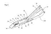
- the front loader further comprises a parking stand device 28 arranged on the front loader rocker 12, as described in detail in FIG. 2 is shown.
- the parking stand device 28 comprises a parking support 30 pivotally hinged to the front loader rocker arm 12 and an arresting strut 32, which is also pivotally hinged to the front loader rocker arm 12 at one end, and which at the other end additionally is slidably connected to the parking support 30.
- the locking strut 32 is fixed to the park support 30 in a locking position (as in FIG FIG. 2 shown), which it occupies as soon as the parking support 30 is pivoted into a parking position, as will be described in more detail below.
- the parking support 30 In the parking position or locking position, the parking support 30 is supported and locked relative to the front loader rocker 12 in a predetermined by the length and the pivot angle of the locking strut 32 position.
- the park support 30 is attached at one end to a pivot pin 34 at a lower portion of the free end of the front loader rocker 12 thereon.
- the locking strut 32 is also attached or hinged above the attachment of the park support 30 at one end with a pivot pin 36 on the front loader rocker 12.
- the park support 30 is formed al U-profile and has two in the direction of the front loader rocker 12 extending side walls 38, 40. On the side walls 38, 40 of the park support 30 are on the inside opposite each a profiled sheet 42, 44 arranged, preferably welded.
- Each profile sheet 42, 44 is provided with a recess 46, through which a guide groove 48, 49 or guide track is provided, which is limited according to a profiled sheet 42, 44 formed profile edge 52, 54 along which a guide means 50 is slidably guided.
- the guide means 50 is designed as a bolt and attached to the other end of the locking strut 32, such that the ends of the bolt in the respective guide grooves 48, 49 of the profiled sheets 42, 44 engage. This will be the Arret réellesstrebe 32 on the one hand (at one end) slidably on the front loader rocker 12 and on the other hand (at the other end) with the bolt formed as a guide means 50, along the profile edges 52, 54 slidably hinged to the parking support 30.
- the formation of the respective guide grooves 48, 49 is in FIG. 3 shown in detail (for example on the profile plate 42).
- the guide elements 50 (bolts) leading profile edges 52, 54 each have sections a direction-changing contour, ie they have a rising in the direction of one end of the parking support 30 course 56, which opens into a first turning point 58, which in turn a opposite the rising course 56, in the opposite direction extending sloping course 60 connects.
- the sloping profile 60 of the respective profile edge 52, 54 in turn opens into a second turning point 62, which is followed by a further rising profile 64, wherein the second turning point 62 and the subsequent further rising profile 64 form a stop 66 which is the end of the respective Guiding grooves 48, 49 forms.
- the stopper 66 is formed semicircular, so that it partially surrounds the respective end of the guide means 50 as soon as it is displaced against the stop 66.
- an operating position P1 a plurality of intermediate positions P2 and a parking position P3 is defined.
- both the park support 30 and the arresting strut 32 are swung in or folded in or folded up until they touch the front loader rocker 12.
- the parking stand device 28 is preferably brought into the operating position when the front loader 10 is to be put into operation, that is coupled to a vehicle.
- parking position P3 (as in FIG. 1 and 2 shown) are both the park support 30 and the Arrest istsstrebe 32 swung out or unfolded.
- the parking stand device 28 is preferably brought into the parking position P3 when the front loader 10 is to be taken out of service, that is to be decoupled from a vehicle and parked or parked. All positions occupied by the parking stand device 28 between the operating position P1 and the parking position P3 represent one of the intermediate positions P2.
- the guide means 50 abuts the profile edge 52 in an initial section of the guide groove 48, 49. If the parking stand device 28 is now unfolded or is to be moved or swiveled out into the parking position P3, the guide means 50 passes through different positions along the profile edge 52 and occupies the positions P2 (1), P2 (2) and P2 (3) in succession , In this case, the guide means 50 is automatically guided by the pivoting movement of the parking support 30 along the profile edge 52 and by the rising curve 56, up to the point of inflection 58 at which the guide means 50, the intermediate position P2 (3) occupies moved or moved.
- the pivoting movement of the parking support 30 can be carried out by an operator or gravity-related by the weight of the parking support.
- the guide means 50 reaches the point of inflection 58.
- the parking stand device 28 assumes a maximum pivoting angle to the front loader rocker 12.
- the gravity of the parking support 30 urges the guide means 50 against the turning point 58, through whose design further pivoting the parking support 30 is blocked.
- the maximum pivot angle is limited.
- the front loader 10 can now be disconnected from the vehicle.
- the front loader 10 begins to tilt due to gravity on the park support 30 and initiates a supporting force, which is transmitted via the locking strut 32 to the guide means 52.
- the support force shifts the guide means 52 in the guide groove 48, 49 along the sloping profile 60 of the profile edges 52, 54 to the second inflection point 62 and urges the guide means against the stopper 66.
- a support force acts on the Arret michsstrebe 32, the guide means 50th set or caught in the stop 66 and the parking stand device 28 locked.
- the guide means 50 is thereby blocked or held by the stop 66 so that the entire supporting torque of the front loader 10 is collected by the parking stand device 28 or the front loader 10 can be supported and parked by the parking stand device 28.
- the parking stand device 28 can then be pivoted back into the operating position P1.
- a pendulum foot 68 is provided, which oscillates by means of a bolt 70 oscillating is mounted on the parking support 30 and provides a footprint or support surface when the parking stand device 28 is pivoted in parking position P3.
- a locking device 72 extends between the pendulum foot 68 and the locking strut 32.
- the locking device 72 comprises a latch 74 received by the side walls 38, 40, which extends tangibly for actuation by the side wall 38 and by a spring 76 which extends between the latch 74 and the bolt 70 is biased toward the free end of the park support 30.
- the latch 74 is provided with a movement clearance formed by a slot 75 formed in the side wall 38.
- a detent means 78 is provided, which is fastened in the form of a provided with a latching notch 80 on the front loader rocker 12, such that the latch 74 engages in the operating position due to its spring bias in the latching notch 80 and holds the parking stand device 28 in the operating position , or these locked in the operating position.
Landscapes
- Engineering & Computer Science (AREA)
- Mechanical Engineering (AREA)
- Mining & Mineral Resources (AREA)
- Civil Engineering (AREA)
- General Engineering & Computer Science (AREA)
- Structural Engineering (AREA)
- Life Sciences & Earth Sciences (AREA)
- Environmental Sciences (AREA)
- Shovels (AREA)
- Agricultural Machines (AREA)
Applications Claiming Priority (1)
| Application Number | Priority Date | Filing Date | Title |
|---|---|---|---|
| DE102010030680A DE102010030680A1 (de) | 2010-06-29 | 2010-06-29 | Frontlader |
Publications (3)
| Publication Number | Publication Date |
|---|---|
| EP2402512A2 true EP2402512A2 (fr) | 2012-01-04 |
| EP2402512A3 EP2402512A3 (fr) | 2014-12-03 |
| EP2402512B1 EP2402512B1 (fr) | 2016-10-26 |
Family
ID=44653619
Family Applications (1)
| Application Number | Title | Priority Date | Filing Date |
|---|---|---|---|
| EP11171011.7A Active EP2402512B1 (fr) | 2010-06-29 | 2011-06-22 | Chargeur frontal pour un tracteur |
Country Status (3)
| Country | Link |
|---|---|
| US (1) | US8998256B2 (fr) |
| EP (1) | EP2402512B1 (fr) |
| DE (1) | DE102010030680A1 (fr) |
Cited By (1)
| Publication number | Priority date | Publication date | Assignee | Title |
|---|---|---|---|---|
| EP3369866A4 (fr) * | 2015-10-27 | 2018-12-05 | Yanmar Co., Ltd. | Chargeur frontal |
Families Citing this family (6)
| Publication number | Priority date | Publication date | Assignee | Title |
|---|---|---|---|---|
| CN104947727A (zh) * | 2015-05-07 | 2015-09-30 | 吴军香 | 一种挖掘机用摆杆 |
| DE102015218524A1 (de) | 2015-09-25 | 2017-03-30 | Deere & Company | Frontlader |
| US10036138B1 (en) * | 2017-12-27 | 2018-07-31 | Kubota Corporation | Front loader and working machine with left and right wires |
| JP6942669B2 (ja) * | 2018-04-19 | 2021-09-29 | 株式会社クボタ | フロントローダのスタンド、フロントローダ及び作業車 |
| US11952743B2 (en) | 2021-10-15 | 2024-04-09 | Deere & Company | Loader with moving apparatus |
| US12398529B2 (en) | 2022-10-20 | 2025-08-26 | Deere & Company | Loader latching assist method and apparatus |
Citations (1)
| Publication number | Priority date | Publication date | Assignee | Title |
|---|---|---|---|---|
| WO2008070901A1 (fr) | 2006-12-13 | 2008-06-19 | Challenge Implements Holdings Pty Limited | Support de stationnement |
Family Cites Families (8)
| Publication number | Priority date | Publication date | Assignee | Title |
|---|---|---|---|---|
| US2852271A (en) * | 1955-03-16 | 1958-09-16 | Albert W Mcdonald | Foldable steps for trailers |
| US4619060A (en) * | 1985-07-02 | 1986-10-28 | Knowlton Leland P | Plow coupling |
| US6039149A (en) * | 1997-09-25 | 2000-03-21 | Cosco Management, Inc. | Collapsible step stool with step movement guide system |
| GB2338470B (en) * | 1998-06-18 | 2002-03-20 | Agco Gmbh & Co | Detachable front loader |
| DE19834773A1 (de) * | 1998-08-01 | 2000-02-03 | Deere & Co | Lader und Fahrzeug mit einem Lader |
| JP3946890B2 (ja) * | 1998-12-09 | 2007-07-18 | ヤンマー農機株式会社 | フロントローダのスタンド構造 |
| AT412659B (de) * | 2002-08-13 | 2005-05-25 | Hauer Franz | Einrichtung zur abstützung der an ein tragfahrzeug, insbesondere einen traktor, ankuppelbaren schwinge für ein arbeitsgerät |
| DE102005053041A1 (de) * | 2005-11-04 | 2007-05-10 | Wilhelm Stoll Maschinenfabrik Gmbh | Abstellfrontlader zum Ankoppeln eines Arbeitswerkzeugs an eine Arbeitsmaschine |
-
2010
- 2010-06-29 DE DE102010030680A patent/DE102010030680A1/de not_active Withdrawn
-
2011
- 2011-06-22 EP EP11171011.7A patent/EP2402512B1/fr active Active
- 2011-06-23 US US13/167,338 patent/US8998256B2/en active Active
Patent Citations (1)
| Publication number | Priority date | Publication date | Assignee | Title |
|---|---|---|---|---|
| WO2008070901A1 (fr) | 2006-12-13 | 2008-06-19 | Challenge Implements Holdings Pty Limited | Support de stationnement |
Cited By (2)
| Publication number | Priority date | Publication date | Assignee | Title |
|---|---|---|---|---|
| EP3369866A4 (fr) * | 2015-10-27 | 2018-12-05 | Yanmar Co., Ltd. | Chargeur frontal |
| US10472794B2 (en) | 2015-10-27 | 2019-11-12 | Yanmar Co., Ltd. | Front loader and work vehicle equipped with the same |
Also Published As
| Publication number | Publication date |
|---|---|
| US20110318154A1 (en) | 2011-12-29 |
| EP2402512B1 (fr) | 2016-10-26 |
| US8998256B2 (en) | 2015-04-07 |
| DE102010030680A1 (de) | 2011-12-29 |
| EP2402512A3 (fr) | 2014-12-03 |
Similar Documents
| Publication | Publication Date | Title |
|---|---|---|
| EP2402512B1 (fr) | Chargeur frontal pour un tracteur | |
| DE69404070T2 (de) | Gerät, das einem Fahrzeug ermöglicht, eine Ladung, wie z.B. einen Kübel, aufzunehmen oder auf dem Boden abzusetzen und ihn evtl. zu entleeren | |
| DE10392430T5 (de) | Heck-Ablage-Systgem für ein Cabrio-Fahrzeug mit einem Hart-Falt-Dach | |
| EP1785114B1 (fr) | Système de support pour malade | |
| DE102019213486A1 (de) | Gargerät mit spezifischer Türöffnungsvorrichtung zum automatischen Schwenken einer versenkbaren Tür des Gargeräts, sowie Verfahren | |
| WO2011069175A1 (fr) | Dispositif de blocage de sortie | |
| DE3501107C2 (fr) | ||
| EP0042608B1 (fr) | Dispositif de support pour un outillage démontable d'un tracteur | |
| EP2829662B1 (fr) | Système de chargeur frontal | |
| EP1921026B1 (fr) | Dispositif de vidange de récipients | |
| EP3159452B1 (fr) | Chargeur frontal | |
| DE60122760T2 (de) | Eine schiebedachkonstruktion für ein fahrzeug sowie ein mit einer solchen schiebedachkonstruktion versehenes fahrzeug | |
| DE1226035B (de) | Fahrzeug mit vorderseitig angeordneter Beladevorrichtung, insbesondere zum Entleeren von Muellsammelbehaeltern in den Wagenaufbau | |
| DE2717207C2 (de) | Überfahr-Tieflader mit zweiteiliger Auffahrrampe | |
| EP2890627B1 (fr) | Dispositif de verrouillage | |
| EP1799913A1 (fr) | Pont a ciseaux modulaire et dispositif d'installation, procede pour installer des ponts a ciseaux modulaires | |
| EP2703259B1 (fr) | Dispositif d'arrêt pour le verrouillage et le déverrouillage d'une cabine basculante d'un véhicule utilitaire | |
| EP1893432B1 (fr) | Berceau de couverture dote d'un dispositif de verrouillage | |
| DE20120964U1 (de) | Abstützvorrichtung für Baumaschinen wie Hydraulikbagger u.dgl. | |
| DE102023112161A1 (de) | Anordnung zum Bewegen eines Deckels für ein Fahrzeugdach und Fahrzeugdach | |
| DE29910216U1 (de) | Baueinheit für fahrbare Anhänger | |
| DE10322980B4 (de) | Kofferraumdeckelanordnung | |
| EP3299556A1 (fr) | Dispositif de verrouillage de battant installé de manière oscillante | |
| EP2204311A1 (fr) | Agencement de ranches | |
| EP1848603B1 (fr) | Toit rigide |
Legal Events
| Date | Code | Title | Description |
|---|---|---|---|
| AK | Designated contracting states |
Kind code of ref document: A2 Designated state(s): AL AT BE BG CH CY CZ DE DK EE ES FI FR GB GR HR HU IE IS IT LI LT LU LV MC MK MT NL NO PL PT RO RS SE SI SK SM TR |
|
| AX | Request for extension of the european patent |
Extension state: BA ME |
|
| PUAI | Public reference made under article 153(3) epc to a published international application that has entered the european phase |
Free format text: ORIGINAL CODE: 0009012 |
|
| PUAL | Search report despatched |
Free format text: ORIGINAL CODE: 0009013 |
|
| AK | Designated contracting states |
Kind code of ref document: A3 Designated state(s): AL AT BE BG CH CY CZ DE DK EE ES FI FR GB GR HR HU IE IS IT LI LT LU LV MC MK MT NL NO PL PT RO RS SE SI SK SM TR |
|
| AX | Request for extension of the european patent |
Extension state: BA ME |
|
| RIC1 | Information provided on ipc code assigned before grant |
Ipc: E02F 3/627 20060101AFI20141030BHEP Ipc: A01D 87/00 20060101ALI20141030BHEP Ipc: A01B 59/048 20060101ALI20141030BHEP Ipc: B62D 49/02 20060101ALI20141030BHEP |
|
| 17P | Request for examination filed |
Effective date: 20150603 |
|
| RBV | Designated contracting states (corrected) |
Designated state(s): AL AT BE BG CH CY CZ DE DK EE ES FI FR GB GR HR HU IE IS IT LI LT LU LV MC MK MT NL NO PL PT RO RS SE SI SK SM TR |
|
| GRAP | Despatch of communication of intention to grant a patent |
Free format text: ORIGINAL CODE: EPIDOSNIGR1 |
|
| RIC1 | Information provided on ipc code assigned before grant |
Ipc: E02F 3/627 20060101AFI20160421BHEP Ipc: A01B 59/048 20060101ALI20160421BHEP Ipc: A01D 87/00 20060101ALI20160421BHEP Ipc: B62D 49/02 20060101ALI20160421BHEP Ipc: E02F 3/96 20060101ALI20160421BHEP |
|
| INTG | Intention to grant announced |
Effective date: 20160519 |
|
| GRAS | Grant fee paid |
Free format text: ORIGINAL CODE: EPIDOSNIGR3 |
|
| GRAA | (expected) grant |
Free format text: ORIGINAL CODE: 0009210 |
|
| AK | Designated contracting states |
Kind code of ref document: B1 Designated state(s): AL AT BE BG CH CY CZ DE DK EE ES FI FR GB GR HR HU IE IS IT LI LT LU LV MC MK MT NL NO PL PT RO RS SE SI SK SM TR |
|
| REG | Reference to a national code |
Ref country code: GB Ref legal event code: FG4D Free format text: NOT ENGLISH |
|
| REG | Reference to a national code |
Ref country code: CH Ref legal event code: EP |
|
| REG | Reference to a national code |
Ref country code: AT Ref legal event code: REF Ref document number: 840145 Country of ref document: AT Kind code of ref document: T Effective date: 20161115 |
|
| REG | Reference to a national code |
Ref country code: IE Ref legal event code: FG4D Free format text: LANGUAGE OF EP DOCUMENT: GERMAN |
|
| REG | Reference to a national code |
Ref country code: DE Ref legal event code: R096 Ref document number: 502011010984 Country of ref document: DE |
|
| REG | Reference to a national code |
Ref country code: LT Ref legal event code: MG4D |
|
| PG25 | Lapsed in a contracting state [announced via postgrant information from national office to epo] |
Ref country code: LV Free format text: LAPSE BECAUSE OF FAILURE TO SUBMIT A TRANSLATION OF THE DESCRIPTION OR TO PAY THE FEE WITHIN THE PRESCRIBED TIME-LIMIT Effective date: 20161026 |
|
| REG | Reference to a national code |
Ref country code: NL Ref legal event code: MP Effective date: 20161026 |
|
| PG25 | Lapsed in a contracting state [announced via postgrant information from national office to epo] |
Ref country code: LT Free format text: LAPSE BECAUSE OF FAILURE TO SUBMIT A TRANSLATION OF THE DESCRIPTION OR TO PAY THE FEE WITHIN THE PRESCRIBED TIME-LIMIT Effective date: 20161026 Ref country code: NO Free format text: LAPSE BECAUSE OF FAILURE TO SUBMIT A TRANSLATION OF THE DESCRIPTION OR TO PAY THE FEE WITHIN THE PRESCRIBED TIME-LIMIT Effective date: 20170126 Ref country code: SE Free format text: LAPSE BECAUSE OF FAILURE TO SUBMIT A TRANSLATION OF THE DESCRIPTION OR TO PAY THE FEE WITHIN THE PRESCRIBED TIME-LIMIT Effective date: 20161026 Ref country code: GR Free format text: LAPSE BECAUSE OF FAILURE TO SUBMIT A TRANSLATION OF THE DESCRIPTION OR TO PAY THE FEE WITHIN THE PRESCRIBED TIME-LIMIT Effective date: 20170127 |
|
| PG25 | Lapsed in a contracting state [announced via postgrant information from national office to epo] |
Ref country code: HR Free format text: LAPSE BECAUSE OF FAILURE TO SUBMIT A TRANSLATION OF THE DESCRIPTION OR TO PAY THE FEE WITHIN THE PRESCRIBED TIME-LIMIT Effective date: 20161026 Ref country code: RS Free format text: LAPSE BECAUSE OF FAILURE TO SUBMIT A TRANSLATION OF THE DESCRIPTION OR TO PAY THE FEE WITHIN THE PRESCRIBED TIME-LIMIT Effective date: 20161026 Ref country code: PL Free format text: LAPSE BECAUSE OF FAILURE TO SUBMIT A TRANSLATION OF THE DESCRIPTION OR TO PAY THE FEE WITHIN THE PRESCRIBED TIME-LIMIT Effective date: 20161026 Ref country code: NL Free format text: LAPSE BECAUSE OF FAILURE TO SUBMIT A TRANSLATION OF THE DESCRIPTION OR TO PAY THE FEE WITHIN THE PRESCRIBED TIME-LIMIT Effective date: 20161026 Ref country code: ES Free format text: LAPSE BECAUSE OF FAILURE TO SUBMIT A TRANSLATION OF THE DESCRIPTION OR TO PAY THE FEE WITHIN THE PRESCRIBED TIME-LIMIT Effective date: 20161026 Ref country code: PT Free format text: LAPSE BECAUSE OF FAILURE TO SUBMIT A TRANSLATION OF THE DESCRIPTION OR TO PAY THE FEE WITHIN THE PRESCRIBED TIME-LIMIT Effective date: 20170227 Ref country code: FI Free format text: LAPSE BECAUSE OF FAILURE TO SUBMIT A TRANSLATION OF THE DESCRIPTION OR TO PAY THE FEE WITHIN THE PRESCRIBED TIME-LIMIT Effective date: 20161026 Ref country code: IS Free format text: LAPSE BECAUSE OF FAILURE TO SUBMIT A TRANSLATION OF THE DESCRIPTION OR TO PAY THE FEE WITHIN THE PRESCRIBED TIME-LIMIT Effective date: 20170226 |
|
| REG | Reference to a national code |
Ref country code: FR Ref legal event code: PLFP Year of fee payment: 7 |
|
| REG | Reference to a national code |
Ref country code: DE Ref legal event code: R097 Ref document number: 502011010984 Country of ref document: DE |
|
| PG25 | Lapsed in a contracting state [announced via postgrant information from national office to epo] |
Ref country code: SK Free format text: LAPSE BECAUSE OF FAILURE TO SUBMIT A TRANSLATION OF THE DESCRIPTION OR TO PAY THE FEE WITHIN THE PRESCRIBED TIME-LIMIT Effective date: 20161026 Ref country code: DK Free format text: LAPSE BECAUSE OF FAILURE TO SUBMIT A TRANSLATION OF THE DESCRIPTION OR TO PAY THE FEE WITHIN THE PRESCRIBED TIME-LIMIT Effective date: 20161026 Ref country code: RO Free format text: LAPSE BECAUSE OF FAILURE TO SUBMIT A TRANSLATION OF THE DESCRIPTION OR TO PAY THE FEE WITHIN THE PRESCRIBED TIME-LIMIT Effective date: 20161026 Ref country code: EE Free format text: LAPSE BECAUSE OF FAILURE TO SUBMIT A TRANSLATION OF THE DESCRIPTION OR TO PAY THE FEE WITHIN THE PRESCRIBED TIME-LIMIT Effective date: 20161026 Ref country code: CZ Free format text: LAPSE BECAUSE OF FAILURE TO SUBMIT A TRANSLATION OF THE DESCRIPTION OR TO PAY THE FEE WITHIN THE PRESCRIBED TIME-LIMIT Effective date: 20161026 |
|
| PG25 | Lapsed in a contracting state [announced via postgrant information from national office to epo] |
Ref country code: SM Free format text: LAPSE BECAUSE OF FAILURE TO SUBMIT A TRANSLATION OF THE DESCRIPTION OR TO PAY THE FEE WITHIN THE PRESCRIBED TIME-LIMIT Effective date: 20161026 Ref country code: IT Free format text: LAPSE BECAUSE OF FAILURE TO SUBMIT A TRANSLATION OF THE DESCRIPTION OR TO PAY THE FEE WITHIN THE PRESCRIBED TIME-LIMIT Effective date: 20161026 Ref country code: BG Free format text: LAPSE BECAUSE OF FAILURE TO SUBMIT A TRANSLATION OF THE DESCRIPTION OR TO PAY THE FEE WITHIN THE PRESCRIBED TIME-LIMIT Effective date: 20170126 |
|
| PLBE | No opposition filed within time limit |
Free format text: ORIGINAL CODE: 0009261 |
|
| STAA | Information on the status of an ep patent application or granted ep patent |
Free format text: STATUS: NO OPPOSITION FILED WITHIN TIME LIMIT |
|
| 26N | No opposition filed |
Effective date: 20170727 |
|
| PG25 | Lapsed in a contracting state [announced via postgrant information from national office to epo] |
Ref country code: SI Free format text: LAPSE BECAUSE OF FAILURE TO SUBMIT A TRANSLATION OF THE DESCRIPTION OR TO PAY THE FEE WITHIN THE PRESCRIBED TIME-LIMIT Effective date: 20161026 |
|
| PG25 | Lapsed in a contracting state [announced via postgrant information from national office to epo] |
Ref country code: MC Free format text: LAPSE BECAUSE OF FAILURE TO SUBMIT A TRANSLATION OF THE DESCRIPTION OR TO PAY THE FEE WITHIN THE PRESCRIBED TIME-LIMIT Effective date: 20161026 |
|
| REG | Reference to a national code |
Ref country code: CH Ref legal event code: PL |
|
| REG | Reference to a national code |
Ref country code: IE Ref legal event code: MM4A |
|
| PG25 | Lapsed in a contracting state [announced via postgrant information from national office to epo] |
Ref country code: LU Free format text: LAPSE BECAUSE OF NON-PAYMENT OF DUE FEES Effective date: 20170622 Ref country code: IE Free format text: LAPSE BECAUSE OF NON-PAYMENT OF DUE FEES Effective date: 20170622 Ref country code: LI Free format text: LAPSE BECAUSE OF NON-PAYMENT OF DUE FEES Effective date: 20170630 Ref country code: CH Free format text: LAPSE BECAUSE OF NON-PAYMENT OF DUE FEES Effective date: 20170630 |
|
| REG | Reference to a national code |
Ref country code: BE Ref legal event code: MM Effective date: 20170630 |
|
| REG | Reference to a national code |
Ref country code: FR Ref legal event code: PLFP Year of fee payment: 8 |
|
| REG | Reference to a national code |
Ref country code: AT Ref legal event code: MM01 Ref document number: 840145 Country of ref document: AT Kind code of ref document: T Effective date: 20170622 |
|
| PG25 | Lapsed in a contracting state [announced via postgrant information from national office to epo] |
Ref country code: BE Free format text: LAPSE BECAUSE OF NON-PAYMENT OF DUE FEES Effective date: 20170630 |
|
| PG25 | Lapsed in a contracting state [announced via postgrant information from national office to epo] |
Ref country code: MT Free format text: LAPSE BECAUSE OF FAILURE TO SUBMIT A TRANSLATION OF THE DESCRIPTION OR TO PAY THE FEE WITHIN THE PRESCRIBED TIME-LIMIT Effective date: 20161026 |
|
| PG25 | Lapsed in a contracting state [announced via postgrant information from national office to epo] |
Ref country code: AT Free format text: LAPSE BECAUSE OF NON-PAYMENT OF DUE FEES Effective date: 20170622 |
|
| PG25 | Lapsed in a contracting state [announced via postgrant information from national office to epo] |
Ref country code: HU Free format text: LAPSE BECAUSE OF FAILURE TO SUBMIT A TRANSLATION OF THE DESCRIPTION OR TO PAY THE FEE WITHIN THE PRESCRIBED TIME-LIMIT; INVALID AB INITIO Effective date: 20110622 |
|
| PG25 | Lapsed in a contracting state [announced via postgrant information from national office to epo] |
Ref country code: CY Free format text: LAPSE BECAUSE OF NON-PAYMENT OF DUE FEES Effective date: 20161026 |
|
| PG25 | Lapsed in a contracting state [announced via postgrant information from national office to epo] |
Ref country code: MK Free format text: LAPSE BECAUSE OF FAILURE TO SUBMIT A TRANSLATION OF THE DESCRIPTION OR TO PAY THE FEE WITHIN THE PRESCRIBED TIME-LIMIT Effective date: 20161026 |
|
| PG25 | Lapsed in a contracting state [announced via postgrant information from national office to epo] |
Ref country code: TR Free format text: LAPSE BECAUSE OF FAILURE TO SUBMIT A TRANSLATION OF THE DESCRIPTION OR TO PAY THE FEE WITHIN THE PRESCRIBED TIME-LIMIT Effective date: 20161026 |
|
| PG25 | Lapsed in a contracting state [announced via postgrant information from national office to epo] |
Ref country code: AL Free format text: LAPSE BECAUSE OF FAILURE TO SUBMIT A TRANSLATION OF THE DESCRIPTION OR TO PAY THE FEE WITHIN THE PRESCRIBED TIME-LIMIT Effective date: 20161026 |
|
| PGFP | Annual fee paid to national office [announced via postgrant information from national office to epo] |
Ref country code: DE Payment date: 20250521 Year of fee payment: 15 |
|
| PGFP | Annual fee paid to national office [announced via postgrant information from national office to epo] |
Ref country code: GB Payment date: 20250627 Year of fee payment: 15 |
|
| PGFP | Annual fee paid to national office [announced via postgrant information from national office to epo] |
Ref country code: FR Payment date: 20250625 Year of fee payment: 15 |