EP2403113A1 - Barre de stator - Google Patents
Barre de stator Download PDFInfo
- Publication number
- EP2403113A1 EP2403113A1 EP10168235A EP10168235A EP2403113A1 EP 2403113 A1 EP2403113 A1 EP 2403113A1 EP 10168235 A EP10168235 A EP 10168235A EP 10168235 A EP10168235 A EP 10168235A EP 2403113 A1 EP2403113 A1 EP 2403113A1
- Authority
- EP
- European Patent Office
- Prior art keywords
- permittivity
- mica tape
- stator bar
- insulation
- mica
- Prior art date
- Legal status (The legal status is an assumption and is not a legal conclusion. Google has not performed a legal analysis and makes no representation as to the accuracy of the status listed.)
- Withdrawn
Links
Images


Classifications
-
- H—ELECTRICITY
- H02—GENERATION; CONVERSION OR DISTRIBUTION OF ELECTRIC POWER
- H02K—DYNAMO-ELECTRIC MACHINES
- H02K3/00—Details of windings
- H02K3/32—Windings characterised by the shape, form or construction of the insulation
- H02K3/40—Windings characterised by the shape, form or construction of the insulation for high voltage, e.g. affording protection against corona discharges
-
- H—ELECTRICITY
- H02—GENERATION; CONVERSION OR DISTRIBUTION OF ELECTRIC POWER
- H02K—DYNAMO-ELECTRIC MACHINES
- H02K3/00—Details of windings
- H02K3/04—Windings characterised by the conductor shape, form or construction, e.g. with bar conductors
- H02K3/12—Windings characterised by the conductor shape, form or construction, e.g. with bar conductors arranged in slots
- H02K3/14—Windings characterised by the conductor shape, form or construction, e.g. with bar conductors arranged in slots with transposed conductors, e.g. twisted conductors
Definitions
- the present invention relates to a stator bar of a large rotating electric machine such as a generator, in particular an indirectly cooled generator with more than 100 MW output power and nominal voltage greater than 10 kVAC.
- Stator bars are known to comprise a plurality of interwoven conductive copper strands defining a conductive element (i.e. the so-called green bar) having a rectangular shape (plain Roebel bars).
- This bar is covered with insulation typically made of a mica tape impregnated with a resin (insulated Roebel bar).
- the beneficial effect of the rounding is quite high when the radius is small, but when increasing the radius the beneficial effect decreases and for a radius of about 2.5 millimetres the beneficial effect cannot be practically further improved in this way.
- WO 2007/139,490 discloses to vary the insulation permittivity in the circumferential direction, such that the insulation has a higher permittivity at its corners.
- DE 198 11 370 discloses to vary the insulation permittivity in the radial direction.
- model calculations showed that when the ratio ⁇ corners / ⁇ elswere between the insulation permittivity at the corners (close to the conductive element) and the insulation permittivity elsewhere (in the radial direction) is greater than an optimum value, an electric field is induced at the transition that may be higher than the field at the corners (close to the conductive element) with insulation having a uniform permittivity (i.e. a single permittivity value).
- the technical aim of the present invention is therefore to provide a stator bar by which the said problems of the known art are eliminated.
- an aspect of the invention is to provide a stator bar in which the electric field peaks at the conductive element corners (these are the most electrically stressed zones of the stator bars) are reduced.
- Another aspect of the invention is to provide a stator bar in which the dielectric material is efficiently used, such that high permittivity insulation is only used where needed.
- stator bar in particular a high voltage stator bar
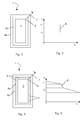
- the stator bar 1 comprises a substantially quadrangular conductive element 2 made of a plurality of interwoven strands 3 (green bar) and an electric insulation 4 applied around it to define a main insulation of the stator bar.
- the electric insulation 4 has a permittivity at its corners 5 that decreases from an inner insulation zone 6 facing the conductive element 2 towards an outer insulation zone 7.
- Change in permittivity also depends on the radius R of the corners 5 (see figure 8 ), since the radius R influences the electric field.
- the permittivity decreases by less than 60% when the radius R of the corner 5 is less than 3 millimetres and preferably between 35-45% when the corner radius R is comprised between 1.5-2.5 millimetres.
- the selected differential permittivity between the zones 6 and 7 lets an electric field be generated at the transition zone between the dielectric materials having different permittivity that is generally limited and in particular smaller than the electric field peaks generated when the insulation 4 has only one permittivity value.
- the insulation 4 comprises a mica tape impregnated with a resin.
- the insulation comprises a first mica tape 4a wrapped around the conductive element 2 and a second mica tape 4b wrapped around the first mica tape 4a.
- the first mica tape permittivity ⁇ 1 is higher than the second mica tape permittivity ⁇ 2 .
- first mica tape 4a and the second mica tape 4b are made of different types of mica having different permittivity.
- the first mica tape 4a is made of muscovite mica and the second mica tape 4b is made of phlogopite mica.
- Figure 3 shows the permittivity run in the direction of maximum field (being the radial direction x) through the insulation 4.
- the insulation 4 has the first permittivity ⁇ 1 at the zones 6 of the insulation 4 close to the conductive element 2; this part of the insulation is made of the first mica tape 4a.
- the outer zones 7 of the insulation 4 are made of the second mica tape 4b and have a lower permittivity ⁇ 2 .
- a permittivity step 8 is defined.
- the first mica tape 4a at the inner insulation zones 6 close to the conductive element 2 comprises particles 9 having high permittivity and the second mica tape 4b at the outer insulation zones 7 has a lower amount or no particles 9; in the embodiment shown only the mica tape 4a has the particles 9.
- these particles 9 are Al 2 O 3 particles.
- the permittivity varies as shown in figure 5 (that shows the permittivity run in the direction of maximum field being the radial direction x); as shown the permittivity is not constant through the insulation 4 but it has two gradually decreasing areas with a kind of step 8 inbetween.
- the different permittivity through the insulation 4 is achieved by changing the resin content of the mica tape 10.
- the inner insulation zones 6 close to the conductive element 2 have a lower resin content than the insulation at the outer insulation zones 7.
- the mica tape 10 constituting the insulation 4 may be wrapped with different wrapping tension.
- the mica tape at the inner insulation zones 6 is more compressed than the following mica tape at the outer insulation zones 7, this causes the resin to be pressed out from the mica tape at the zones 6 in a larger amount than from the mica tape at the zones 7; therefore, the resin is retained in the outer insulation zones 7 in a greater amount than in the inner insulation zones 6.
- the permittivity in the insulation may define one or more steps or may at least partly continuously decrease (see figure 7 that shows the permittivity run in the direction of maximum field being the radial direction x).
- changing of the resin content to change the insulation permittivity can be achieved using mica tapes having different compressibility.
- strips of mica tape that are not wrapped but aligned parallel to the corners of the conductive element can also be used to change the resin content and, thus, to achieve a change in permittivity.
Landscapes
- Engineering & Computer Science (AREA)
- Power Engineering (AREA)
- Insulation, Fastening Of Motor, Generator Windings (AREA)
Priority Applications (5)
| Application Number | Priority Date | Filing Date | Title |
|---|---|---|---|
| EP10168235A EP2403113A1 (fr) | 2010-07-02 | 2010-07-02 | Barre de stator |
| EP11171037A EP2403114A1 (fr) | 2010-07-02 | 2011-06-22 | Barre de stator |
| US13/173,632 US8952256B2 (en) | 2010-07-02 | 2011-06-30 | Stator bar |
| JP2011147551A JP2012016273A (ja) | 2010-07-02 | 2011-07-01 | 固定子バー |
| US14/513,924 US20150028701A1 (en) | 2010-07-02 | 2014-10-14 | Stator bar |
Applications Claiming Priority (1)
| Application Number | Priority Date | Filing Date | Title |
|---|---|---|---|
| EP10168235A EP2403113A1 (fr) | 2010-07-02 | 2010-07-02 | Barre de stator |
Publications (1)
| Publication Number | Publication Date |
|---|---|
| EP2403113A1 true EP2403113A1 (fr) | 2012-01-04 |
Family
ID=43858282
Family Applications (2)
| Application Number | Title | Priority Date | Filing Date |
|---|---|---|---|
| EP10168235A Withdrawn EP2403113A1 (fr) | 2010-07-02 | 2010-07-02 | Barre de stator |
| EP11171037A Withdrawn EP2403114A1 (fr) | 2010-07-02 | 2011-06-22 | Barre de stator |
Family Applications After (1)
| Application Number | Title | Priority Date | Filing Date |
|---|---|---|---|
| EP11171037A Withdrawn EP2403114A1 (fr) | 2010-07-02 | 2011-06-22 | Barre de stator |
Country Status (3)
| Country | Link |
|---|---|
| US (1) | US8952256B2 (fr) |
| EP (2) | EP2403113A1 (fr) |
| JP (1) | JP2012016273A (fr) |
Cited By (2)
| Publication number | Priority date | Publication date | Assignee | Title |
|---|---|---|---|---|
| CN111371268A (zh) * | 2020-04-24 | 2020-07-03 | 哈尔滨电机厂有限责任公司 | 一种双层复合主绝缘结构的定子线棒制造方法 |
| WO2024106834A1 (fr) * | 2022-11-16 | 2024-05-23 | 엘지마그나 이파워트레인 주식회사 | Stator et moteur le comprenant |
Families Citing this family (9)
| Publication number | Priority date | Publication date | Assignee | Title |
|---|---|---|---|---|
| US11979070B2 (en) * | 2012-02-24 | 2024-05-07 | Integrated Power Services LLC | Electrical machine coil insulation system and method |
| WO2013145344A1 (fr) * | 2012-03-27 | 2013-10-03 | 三菱電機株式会社 | Stator et machine dynamoélectrique le comprenant |
| JP6315389B2 (ja) * | 2014-02-10 | 2018-04-25 | パナソニックIpマネジメント株式会社 | 有機エレクトロルミネッセンス素子及び照明装置 |
| US9059616B1 (en) | 2014-08-20 | 2015-06-16 | Dantam K. Rao | Insulation system for a stator bar with low partial discharge |
| CN107099844B (zh) * | 2016-02-23 | 2021-01-05 | 松下知识产权经营株式会社 | Ramo4基板及其制造方法 |
| JP6522273B1 (ja) * | 2018-10-11 | 2019-05-29 | 三菱電機株式会社 | 固定子コイル、その製造方法及び回転電機 |
| JP7383899B2 (ja) * | 2019-03-29 | 2023-11-21 | 株式会社デンソー | 回転電機 |
| US20250119018A1 (en) * | 2021-09-21 | 2025-04-10 | Mitsubishi Electric Corporation | Rotary machine coil, method for manufacturing same, and rotary machine |
| JP7801931B2 (ja) * | 2022-03-30 | 2026-01-19 | 三菱重工業株式会社 | コイル用線材、コイル用線材の製造方法、ステータ、及び電動機 |
Citations (5)
| Publication number | Priority date | Publication date | Assignee | Title |
|---|---|---|---|---|
| FR2290071A1 (fr) * | 1974-10-29 | 1976-05-28 | Westinghouse Electric Corp | Elimination de l'effet corona dans les enroulements a haute tension |
| DE19811370A1 (de) | 1998-03-16 | 1999-09-23 | Abb Research Ltd | Variation der Dielektrizitätskonstanten in Isolierungen von Hochspannungswicklungen elektrischer Maschinen |
| EP0951132A2 (fr) * | 1998-04-18 | 1999-10-20 | Abb Research Ltd. | Barre d'enroulement pour machine électrique de haute tension et procédé pour la fabrication d'une telle barre |
| US20020029897A1 (en) * | 2000-09-14 | 2002-03-14 | Younsi A. Karim | Graded electric field insulation system for dynamoelectric machine |
| WO2007139490A1 (fr) | 2006-05-29 | 2007-12-06 | Abb Technology Ltd. | Isolation d'enroulement de stator |
Family Cites Families (3)
| Publication number | Priority date | Publication date | Assignee | Title |
|---|---|---|---|---|
| EP0884825B1 (fr) * | 1997-05-14 | 2003-12-17 | Toyota Jidosha Kabushiki Kaisha | Stator pour moteur électrique |
| EP1950866A1 (fr) * | 2007-01-25 | 2008-07-30 | ALSTOM Technology Ltd | Procédé de fabrication d'une barre conductrice d'une machine électrique tournante et barre conductrice fabriquée d'après ce procédé |
| US7655868B2 (en) * | 2008-01-08 | 2010-02-02 | General Electric Company | Stator bar components with high thermal conductivity |
-
2010
- 2010-07-02 EP EP10168235A patent/EP2403113A1/fr not_active Withdrawn
-
2011
- 2011-06-22 EP EP11171037A patent/EP2403114A1/fr not_active Withdrawn
- 2011-06-30 US US13/173,632 patent/US8952256B2/en not_active Expired - Fee Related
- 2011-07-01 JP JP2011147551A patent/JP2012016273A/ja not_active Withdrawn
Patent Citations (5)
| Publication number | Priority date | Publication date | Assignee | Title |
|---|---|---|---|---|
| FR2290071A1 (fr) * | 1974-10-29 | 1976-05-28 | Westinghouse Electric Corp | Elimination de l'effet corona dans les enroulements a haute tension |
| DE19811370A1 (de) | 1998-03-16 | 1999-09-23 | Abb Research Ltd | Variation der Dielektrizitätskonstanten in Isolierungen von Hochspannungswicklungen elektrischer Maschinen |
| EP0951132A2 (fr) * | 1998-04-18 | 1999-10-20 | Abb Research Ltd. | Barre d'enroulement pour machine électrique de haute tension et procédé pour la fabrication d'une telle barre |
| US20020029897A1 (en) * | 2000-09-14 | 2002-03-14 | Younsi A. Karim | Graded electric field insulation system for dynamoelectric machine |
| WO2007139490A1 (fr) | 2006-05-29 | 2007-12-06 | Abb Technology Ltd. | Isolation d'enroulement de stator |
Non-Patent Citations (1)
| Title |
|---|
| REHDER R H ET AL: "CORONA DETERIORATION REDUCTION IN LARGE ELECTRICAL MACHINE INSULATION", IEEE INDUSTRY APPLICATIONS MAGAZINE, IEEE SERVICE CENTER, PISCATAWAY, NJ, US, vol. 1, no. 1, 1 January 1995 (1995-01-01), pages 12 - 15, XP000497975, ISSN: 1077-2618, DOI: 10.1109/2943.378056 * |
Cited By (2)
| Publication number | Priority date | Publication date | Assignee | Title |
|---|---|---|---|---|
| CN111371268A (zh) * | 2020-04-24 | 2020-07-03 | 哈尔滨电机厂有限责任公司 | 一种双层复合主绝缘结构的定子线棒制造方法 |
| WO2024106834A1 (fr) * | 2022-11-16 | 2024-05-23 | 엘지마그나 이파워트레인 주식회사 | Stator et moteur le comprenant |
Also Published As
| Publication number | Publication date |
|---|---|
| EP2403114A1 (fr) | 2012-01-04 |
| US20120001514A1 (en) | 2012-01-05 |
| US8952256B2 (en) | 2015-02-10 |
| JP2012016273A (ja) | 2012-01-19 |
Similar Documents
| Publication | Publication Date | Title |
|---|---|---|
| EP2403114A1 (fr) | Barre de stator | |
| DE69727669T2 (de) | Hochspannungsanlagen mit elektrischen Motoren | |
| US11063488B2 (en) | Stator for electric rotating machine | |
| KR20000016040A (ko) | 고전압 권선용 절연 전도체 및 상기 전도체의 제조 방법 | |
| BG63415B1 (bg) | Електромагнитно устройство | |
| US9722465B2 (en) | Stator for rotating electric machine and method for manufacturing stator for rotating electric machine | |
| WO2013048932A2 (fr) | Moteur électrique polyphasé | |
| US20030141775A1 (en) | Method of making a dynamoelectric machine conductor bar and method of making a conductor bar dynamoelectric machine, the bar and the machine | |
| AU5890398A (en) | Winding in transformer or inductor | |
| US7262537B2 (en) | Electric motor and generator component having a plurality of windings made from a plurality of individually conductive wires | |
| KR20010032377A (ko) | 고전압 기계 권선용 절연 도체 | |
| EP2582018A1 (fr) | Stator d'une machine électrique doté d'une protection contre l'effet de couronne passante | |
| EP1266438B1 (fr) | Machine electrique tournante | |
| KR102025054B1 (ko) | 권선을 위한 고전압 케이블 및 그것을 포함하는 전자기 유도 디바이스 | |
| US20150028701A1 (en) | Stator bar | |
| EP1903662A1 (fr) | Machine tournante haute tension et installation électrique comportant une telle machine | |
| KR20130139805A (ko) | 부하 토오크가 감소하는 다극 다상 직류 발전기 | |
| CN103904806A (zh) | 15.75kV级发电机定子多胶模压减薄优化结构 | |
| JP6014833B2 (ja) | 回転電機のコイル | |
| CN105917552A (zh) | 绝缘系统、定子、电机、尤其涡轮发电机,以及用于使导电元件绝缘的方法 | |
| EP2405558A1 (fr) | Barre de stator | |
| EP2745384A2 (fr) | Blindage extérieur anti-couronne pour une machine électrique | |
| JP2937584B2 (ja) | 回転電機の巻線 | |
| WO2018215213A1 (fr) | Enroulement de bobine | |
| WO2007139490A1 (fr) | Isolation d'enroulement de stator |
Legal Events
| Date | Code | Title | Description |
|---|---|---|---|
| AK | Designated contracting states |
Kind code of ref document: A1 Designated state(s): AL AT BE BG CH CY CZ DE DK EE ES FI FR GB GR HR HU IE IS IT LI LT LU LV MC MK MT NL NO PL PT RO SE SI SK SM TR |
|
| AX | Request for extension of the european patent |
Extension state: BA ME RS |
|
| PUAI | Public reference made under article 153(3) epc to a published international application that has entered the european phase |
Free format text: ORIGINAL CODE: 0009012 |
|
| STAA | Information on the status of an ep patent application or granted ep patent |
Free format text: STATUS: THE APPLICATION IS DEEMED TO BE WITHDRAWN |
|
| 18D | Application deemed to be withdrawn |
Effective date: 20120705 |