EP2403446B1 - Tampon à barrière de fluide - Google Patents
Tampon à barrière de fluide Download PDFInfo
- Publication number
- EP2403446B1 EP2403446B1 EP10710688.2A EP10710688A EP2403446B1 EP 2403446 B1 EP2403446 B1 EP 2403446B1 EP 10710688 A EP10710688 A EP 10710688A EP 2403446 B1 EP2403446 B1 EP 2403446B1
- Authority
- EP
- European Patent Office
- Prior art keywords
- layer
- product
- storage
- barrier
- layers
- Prior art date
- Legal status (The legal status is an assumption and is not a legal conclusion. Google has not performed a legal analysis and makes no representation as to the accuracy of the status listed.)
- Not-in-force
Links
- 230000004888 barrier function Effects 0.000 title claims description 52
- 239000012530 fluid Substances 0.000 title description 15
- 238000003860 storage Methods 0.000 claims description 77
- 239000007788 liquid Substances 0.000 claims description 52
- 239000000126 substance Substances 0.000 claims description 17
- 239000000463 material Substances 0.000 claims description 16
- 238000003466 welding Methods 0.000 claims description 13
- 239000000835 fiber Substances 0.000 claims description 3
- 238000000034 method Methods 0.000 description 10
- 239000006071 cream Substances 0.000 description 7
- 230000002745 absorbent Effects 0.000 description 5
- 239000002250 absorbent Substances 0.000 description 5
- 239000004480 active ingredient Substances 0.000 description 3
- 239000000853 adhesive Substances 0.000 description 3
- 230000001070 adhesive effect Effects 0.000 description 3
- 238000010276 construction Methods 0.000 description 3
- 208000000453 Skin Neoplasms Diseases 0.000 description 2
- 239000002537 cosmetic Substances 0.000 description 2
- 230000002093 peripheral effect Effects 0.000 description 2
- 239000002985 plastic film Substances 0.000 description 2
- 229920006255 plastic film Polymers 0.000 description 2
- 238000007789 sealing Methods 0.000 description 2
- 208000017520 skin disease Diseases 0.000 description 2
- 239000002966 varnish Substances 0.000 description 2
- JIAARYAFYJHUJI-UHFFFAOYSA-L zinc dichloride Chemical compound [Cl-].[Cl-].[Zn+2] JIAARYAFYJHUJI-UHFFFAOYSA-L 0.000 description 2
- 241000894006 Bacteria Species 0.000 description 1
- 206010029098 Neoplasm skin Diseases 0.000 description 1
- 208000003251 Pruritus Diseases 0.000 description 1
- 230000015556 catabolic process Effects 0.000 description 1
- 239000003795 chemical substances by application Substances 0.000 description 1
- 239000000356 contaminant Substances 0.000 description 1
- 238000006731 degradation reaction Methods 0.000 description 1
- 239000007933 dermal patch Substances 0.000 description 1
- 239000003599 detergent Substances 0.000 description 1
- 239000006185 dispersion Substances 0.000 description 1
- 239000000428 dust Substances 0.000 description 1
- 230000000694 effects Effects 0.000 description 1
- 229920001971 elastomer Polymers 0.000 description 1
- 239000004744 fabric Substances 0.000 description 1
- 230000009969 flowable effect Effects 0.000 description 1
- 239000007789 gas Substances 0.000 description 1
- 239000003292 glue Substances 0.000 description 1
- 239000012678 infectious agent Substances 0.000 description 1
- 238000005304 joining Methods 0.000 description 1
- 238000004519 manufacturing process Methods 0.000 description 1
- 201000001441 melanoma Diseases 0.000 description 1
- 239000000203 mixture Substances 0.000 description 1
- 238000004806 packaging method and process Methods 0.000 description 1
- 239000000825 pharmaceutical preparation Substances 0.000 description 1
- 229940127557 pharmaceutical product Drugs 0.000 description 1
- 238000005498 polishing Methods 0.000 description 1
- 229920006395 saturated elastomer Polymers 0.000 description 1
- 201000000849 skin cancer Diseases 0.000 description 1
- 239000000344 soap Substances 0.000 description 1
- 238000003892 spreading Methods 0.000 description 1
- 239000011232 storage material Substances 0.000 description 1
- 235000005074 zinc chloride Nutrition 0.000 description 1
- 239000011592 zinc chloride Substances 0.000 description 1
Images

Classifications
-
- A—HUMAN NECESSITIES
- A45—HAND OR TRAVELLING ARTICLES
- A45D—HAIRDRESSING OR SHAVING EQUIPMENT; EQUIPMENT FOR COSMETICS OR COSMETIC TREATMENTS, e.g. FOR MANICURING OR PEDICURING
- A45D34/00—Containers or accessories specially adapted for handling liquid toiletry or cosmetic substances, e.g. perfumes
- A45D34/04—Appliances specially adapted for applying liquid, e.g. using roller or ball
-
- A—HUMAN NECESSITIES
- A45—HAND OR TRAVELLING ARTICLES
- A45D—HAIRDRESSING OR SHAVING EQUIPMENT; EQUIPMENT FOR COSMETICS OR COSMETIC TREATMENTS, e.g. FOR MANICURING OR PEDICURING
- A45D37/00—Sachet pads specially adapted for liquid toiletry or cosmetic substances
-
- A—HUMAN NECESSITIES
- A61—MEDICAL OR VETERINARY SCIENCE; HYGIENE
- A61F—FILTERS IMPLANTABLE INTO BLOOD VESSELS; PROSTHESES; DEVICES PROVIDING PATENCY TO, OR PREVENTING COLLAPSING OF, TUBULAR STRUCTURES OF THE BODY, e.g. STENTS; ORTHOPAEDIC, NURSING OR CONTRACEPTIVE DEVICES; FOMENTATION; TREATMENT OR PROTECTION OF EYES OR EARS; BANDAGES, DRESSINGS OR ABSORBENT PADS; FIRST-AID KITS
- A61F13/00—Bandages or dressings; Absorbent pads
-
- A—HUMAN NECESSITIES
- A45—HAND OR TRAVELLING ARTICLES
- A45D—HAIRDRESSING OR SHAVING EQUIPMENT; EQUIPMENT FOR COSMETICS OR COSMETIC TREATMENTS, e.g. FOR MANICURING OR PEDICURING
- A45D2200/00—Details not otherwise provided for in A45D
- A45D2200/10—Details of applicators
- A45D2200/1009—Applicators comprising a pad, tissue, sponge, or the like
- A45D2200/1018—Applicators comprising a pad, tissue, sponge, or the like comprising a pad, i.e. a cushion-like mass of soft material, with or without gripping means
-
- A—HUMAN NECESSITIES
- A45—HAND OR TRAVELLING ARTICLES
- A45D—HAIRDRESSING OR SHAVING EQUIPMENT; EQUIPMENT FOR COSMETICS OR COSMETIC TREATMENTS, e.g. FOR MANICURING OR PEDICURING
- A45D2200/00—Details not otherwise provided for in A45D
- A45D2200/10—Details of applicators
- A45D2200/1009—Applicators comprising a pad, tissue, sponge, or the like
- A45D2200/1036—Applicators comprising a pad, tissue, sponge, or the like containing a cosmetic substance, e.g. impregnated with liquid or containing a soluble solid substance
-
- A—HUMAN NECESSITIES
- A45—HAND OR TRAVELLING ARTICLES
- A45D—HAIRDRESSING OR SHAVING EQUIPMENT; EQUIPMENT FOR COSMETICS OR COSMETIC TREATMENTS, e.g. FOR MANICURING OR PEDICURING
- A45D40/00—Casings or accessories specially adapted for storing or handling solid or pasty toiletry or cosmetic substances, e.g. shaving soaps or lipsticks
- A45D40/0087—Casings or accessories specially adapted for storing or handling solid or pasty toiletry or cosmetic substances, e.g. shaving soaps or lipsticks for samples
-
- A—HUMAN NECESSITIES
- A61—MEDICAL OR VETERINARY SCIENCE; HYGIENE
- A61F—FILTERS IMPLANTABLE INTO BLOOD VESSELS; PROSTHESES; DEVICES PROVIDING PATENCY TO, OR PREVENTING COLLAPSING OF, TUBULAR STRUCTURES OF THE BODY, e.g. STENTS; ORTHOPAEDIC, NURSING OR CONTRACEPTIVE DEVICES; FOMENTATION; TREATMENT OR PROTECTION OF EYES OR EARS; BANDAGES, DRESSINGS OR ABSORBENT PADS; FIRST-AID KITS
- A61F13/00—Bandages or dressings; Absorbent pads
- A61F2013/00089—Wound bandages
- A61F2013/00297—Wound bandages safety barrier for protection of the operator
-
- A—HUMAN NECESSITIES
- A61—MEDICAL OR VETERINARY SCIENCE; HYGIENE
- A61F—FILTERS IMPLANTABLE INTO BLOOD VESSELS; PROSTHESES; DEVICES PROVIDING PATENCY TO, OR PREVENTING COLLAPSING OF, TUBULAR STRUCTURES OF THE BODY, e.g. STENTS; ORTHOPAEDIC, NURSING OR CONTRACEPTIVE DEVICES; FOMENTATION; TREATMENT OR PROTECTION OF EYES OR EARS; BANDAGES, DRESSINGS OR ABSORBENT PADS; FIRST-AID KITS
- A61F13/00—Bandages or dressings; Absorbent pads
- A61F2013/00361—Plasters
- A61F2013/00902—Plasters containing means
- A61F2013/00906—Plasters containing means for transcutaneous or transdermal drugs application
-
- A—HUMAN NECESSITIES
- A61—MEDICAL OR VETERINARY SCIENCE; HYGIENE
- A61K—PREPARATIONS FOR MEDICAL, DENTAL OR TOILETRY PURPOSES
- A61K9/00—Medicinal preparations characterised by special physical form
- A61K9/70—Web, sheet or filament bases ; Films; Fibres of the matrix type containing drug
- A61K9/7023—Transdermal patches and similar drug-containing composite devices, e.g. cataplasms
- A61K9/703—Transdermal patches and similar drug-containing composite devices, e.g. cataplasms characterised by shape or structure; Details concerning release liner or backing; Refillable patches; User-activated patches
Definitions
- the present invention relates to a device for applying at least one product at a desired place. More particularly, the present invention regards a pad accommodating at least one product, where the construction of the pad will ensure a correct filling of the device and where the product(s) will remain in its stored compartment, without the risk of leaking before the pad is to be used.
- a product there are today different methods available for applying various liquids or colloidal substances, hereinafter referred to as a product, on a desired spot or surface.
- the product can for instance be applied to a surface by the user simply placing the product from a bottle or tube on their hand and then manually spread on the desired surface.
- This method is the most inexpensive, but it is also inefficient, messy and may result in an uneven application of the product.
- the bottles or tubes contain a fairly large quantity of the product and can therefore be inconvenient to carry with the user.
- One other method is to have separate bottles and applicator elements.
- the applicator element will soak up some of the product when they are brought into contact with each other, whereby the user uses the applicator element to disperse the product over a desired spot or surface.
- This method may result in spillage when applying the product to the applicator element, and some of the product may also be wasted as the applicator element itself will absorb some of the product.
- a further problem with this method is that the product to be applied may come in contact with the user's hands, which is not desirable, especially if the product is irritating for the skin.
- Yet another method for applying a product on a desired surface is to use a disposable or single-use applicator which is supplied with a pre-determined quantity of the product.
- Such applicators are manufactured from a disposable material substantially fully infused with the appropriate product, for example, a cleansing cream, and sealed in a container. This results in relatively costly manufacture, since a larger amount of the cosmetic product than is required is applied to the sheet of material.
- the applicator may also be so infused with the product to be applied that it will result in uneven application of the product on the desired surface. It will also be very difficult to control the amount of product transferred from the applicator to the skin, increasing the chance of excessive application of the product.
- the above mentioned product can for instance be a liquid, such as wound cleansing agent, special cleansing liquid for various purposes such as, nail varnish, varnish remnants, glue remnants etc. and the colloidal substances can for instance be shoe cream, cosmetics, moisture creams, cleansing creams, self-tanning creams, various gel products for personal hygiene, soap etc. Furthermore, the product can be pharmaceutical products, such as pain relief, anti-itching agents etc.
- a common feature of the applicators shown in the prior art is that they are neither economical nor able to control the application of a product onto a surface.
- US 3.124.825 describes a nail polish remover, where there is provided a single use, disposable package including a container drawing positioned therebetween an applicator with enough polish remover impregnated therein to remove the polish from all the nails of a user.
- the package consists of a flexible pouch heat sealed at its free edges to form an envelope which seals material contained therein from contact with liquids or gases. Within the pouch is an applicator saturated with the nail polish remover.
- US 5.961.500 describes a prewetted medical wipe with impermeable barrier, where the wipe is constructed by bonding a layer of absorbent material to one side of a barrier sheet that is impermeable to infectious agents and insoluble in dermatological fluids, filling a reservoir in the barrier with a dermatological fluid, and hermetically sealing the absorbent layer between the barrier and a cover.
- the peripheral edges of the absorbent layer are spaced inwardly from the peripheral edges of the barrier to provide a surrounding zone of the impermeable barrier alone.
- the absorbent layer bond to the barrier is resistant to degradation caused by exposure to the dermatological fluid.
- WO 2009/009651 A1 discloses a method of enclosing an active ingredient layer, especially an active ingredient layer comprising a volatile component, between a release liner and a backing layer, and to dermal patches comprising such sealed active ingredient layer.
- WO 00/48541 relates to the treatment of human melanoma, basal and squamous cell skin cancer, and a variety of other skin tumors and skin diseases, where a unit dose packaging of a zinc chloride mixture is used in a dosage specific applicator for the treatment of these skin diseases.
- Another object of the present invention is to provide a device where the product or products will not leak and/or desiccate during storing and transportation.
- a further object of the present invention is to provide an economical device for containing and dispensing a product or products to a surface in a convenient, uniform and simple manner.
- Yet a further object of the present invention is to provide an applicator for products, in the form of a single product which minimizes and possibly alleviates the disadvantages normally associated with use of such products as currently applied, and help make their use easier and more effective.
- a device which can apply at least one product in a controlled manner onto a surface or a spot, where the device comprises several layers that are joined in appropriate ways. Each of the layers of the device has its own specific function.
- the device according to the present invention is especially suitable for accommodating a product or products that are thin and/or having a low viscosity, as it in at least one of the layers of the device is provided a temporary barrier.
- the purpose of the temporary barrier is to delay the product from running over the barrier, whereby the layers can be joined together.
- the device consists of four layers, the layers being a bottom layer, a storage layer, a contact layer and a top layer sealing off the device.
- the bottom layer constitutes the rear surface of the device, and serves to protect the storage layer from desiccation. It will also prevent the user from being soiled during use.
- the bottom layer may also be manufactured as a pocket (comprising an additional outer elastic layer) or comprise a holding device, in order to ease the use of the device.
- the bottom layer may be manufactured from a liquid-impermeable material, for instance a plastic film that has good welding properties, in order to be attached to one or more of the other layers. The attachment between the different layer(s) may for instance be done by means of heat-seal, ultrasonic weld or adhesive to prevent its removal from the other layer(s).
- the storage layer according to the present invention may be provided with a fibre structure with intersecting fibres, where the fibres can be situated in one or several layers.
- the structure of the fibres will form cavities of a size and shape that enable it to contain the specific product that has to be stored.
- the size of the cavities may vary depending on the viscosity of the product to be contained. As the structure substantially is not absorbent, it has to be dosed with or be supplied in another way with a product it has to contain.
- the storage structure may also be manufactured from a material having a different cell structure, for instance a rubber sponge material or a non-woven material, having sufficient porosity to store the product to be applied.
- the storage layer due to the properties of the materials used, will have a "springy effect", where this will result in the storage layer releasing some of the product each time the device is compressed. When the pressure is relieved, the remaining product will be stored in the storage layer.
- the cavities in the storage material may also be made artificially, as one for instance can use a needle, knife or the like, in order to form perforations and/or openings in the storage layer. This is important when a certain amount of a product is to be stored on a specific location in the pad.
- the storage layer may also be manufactured as a multi chambered layer, where this for instance is advantageous when the storage layer contains two or more different products having different density and/or that are not to be mixed before the device is to be used.
- This "chamber-ing" may be achieved by a welding forming a barrier between the chambers, where this barrier will burst or open when a certain pressure is applied to the storage layer.
- a temporary barrier is created in the storage layer. During the filling of the product(s) in the storage layer, the temporary liquid barrier will delay the product running over the temporary liquid barrier, where this delay will be sufficient to join the rest of the layers of the device.
- the contact layer which is the layer that is in contact with the surface on which the product is to be applied, can be a film or a fabric (e.g. non-woven).
- the layer has a suitable structure which is selected according to the application for which the device is to be used. If the device, for instance, is used as a shoe cream applicator, then the contact layer will have a surface that is suited for spreading out and polishing the shoe when the shoe cream is applied. If, for instance, the device is used to cleanse skin with sterile cleansing liquid, the contact layer must then also have a surface that is soft against the skin and preferably have a desired degree of roughness to enable it to remove dirt etc. from the user's skin. In such cases the material must often be sterile before use and may therefore be protected by a separate layer that is torn off before use of the device.
- the different layers in the device are in appropriate ways connected or attached together.
- the bottom layer, the storage layer, the contact layer and a top layer are attached to each other along an inside of their outer edges, thereby forming a sealed storage chamber.
- This attachment or connection between the different layers may for instance be done by heat-seal, ultrasonic weld or adhesive.
- the top layer must then be "welded” in exactly the same way as rest of the layers, i.e. around the welt that forms the sealed storage chamber.
- the different layers are also connected, for instance by adhesion, welding or any other suitable method, around their outer peripheries. This will form a device that is "closed” around its outer edges, except for the pocket opening.
- the connection can be a simple “weld” or a fluid tight "weld”.
- the top layer may be manufactured from a plastic film, a laminate or any other suitable material(s), where the material(s) is substantially impermeable.
- the device When the top layer is removed by tearing, the device is ready for use.
- the product(s) stored in the storage chamber will remain in the storage chamber until the device is subjected to a mechanical pressure.
- the device Before the above described sealed storage chamber is made, the device must be filled with the product(s) it shall accommodate. In order to be able to fill the device with a product that is thin and/or have low viscosity, it is created at least one temporary liquid barrier in the device. This temporary liquid barrier is obtained by "welding" the bottom layer and the storage layer together, where the weld seam will form a closed circuit. The temporary liquid barrier is arranged within the sealed storage chamber.
- one or more needles or nozzles are used to fill the product(s) inside the temporary liquid barrier.
- the needles or nozzles can then either inject the product directly into the temporary liquid barrier, by being brought into the temporary liquid barrier, or the product(s) can be delivered onto a surface of the storage layer, the needles or nozzles being in contact with the surface or also a distance over the surface.
- This sealed storage chamber is a fluid tight chamber, and the product(s) will therefore be "trapped" inside the sealed storage chamber and the substantially impermeable bottom layer and top layer.
- the temporary liquid barrier must not necessary be a closed barrier, as one may also obtain the desired purpose by spot welding, laying a broken weld seam or combining the two.
- each of the storage chambers must have a temporary fluid barrier inside it.
- Yet another possible way to make the temporary liquid barrier is to make at least one of the layers thinner in the area that defines the temporary liquid barrier, this creating a sunken area/hollow/hole or "bowl” in the layer(s).
- the product(s) When the different layers are laid together, the product(s) will be supplied through the nozzles or the needles. As the product(s) has low viscosity, it will first fill the sunken area/hollow/hole or "bowl”, and first thereafter will it flow out over the surface of the layer(s). This will give the desired delay of time in order to be able to create the sealed storage chamber.
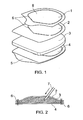
- FIG 1 the principal configuration of a device according to the present invention is shown.
- the device comprises four different layers, where each layer has its own function.
- a bottom layer 4 must prevent the stored product passing through it and is therefore made from a liquid-impermeable material. On its backside, that is the side turning away from a storing layer 3, the bottom layer 4 is joined with an additional elastic pocket layer 5, where these two layers 4, 5, when connected, will form a pocket in the device.
- the pocket layer 5 and the rest of the layers 1-4 are, in appropriate ways, connected around their outer peripheries, only leaving a certain area in the pocket layer 5 unconnected, thereby forming an opening between the bottom layer 4 and the pocket layer 5.
- the user can then put his or her hand into the pocket that is created between the bottom layer 4 and pocket layer 5, when the device is to be used. This pocket will ease the handling of the device and it will also prevent the user's hand becoming soiled.
- the elastic layer 5 can be replaced with a holding device (not shown), for instance a handle or grip device.
- the storage layer 3 contains the liquid and/or colloidal substance that is to be applied onto a desired surface or spot, where the product substance can either be supplied to the storage layer 3 before the different layers 1- 4 are connected together, or it can be supplied after the different layers 2-4 are connected together.
- the product that is to be contained in the storage layer 3 can for instance be supplied by different kinds of nozzles or needles etc.
- a contact layer 2 is arranged, where this contact layer 2 will allow the liquid and or/colloidal substance to pass through the contact layer 2 from the storage layer 3 and to the surface on which the liquid and/or colloidal substance is to be applied.
- a side of the contact layer 2 that is facing the surface that is to be applied the liquid and/or colloidal substance is such that it will disperse the liquid and/or colloidal substance evenly and sparsely onto the desired surface or spot.
- the device according to the present invention also comprises a top layer 1, where the top layer 1 is manufactured from a substantially impermeable material.
- the top layer 1 is arranged over the contact layer 2, and will therefore protect the contact layer 2 from fouling during storage and transportation. Before the device is to be used, the top layer 1 must be removed, where this can be done by tearing off the top layer 1.
- the top layer 1 is therefore formed with a flap or corner, in order to ease the tearing off.
- the bottom layer 4, storage layer 3, contact layer 2 and the top layer 1 are welded 6 together around an inside of their outer periphery.
- the storage chamber 8 is a closed chamber and the weld 6 will make it fluid tight.
- the weld can for instance be done by heat-seal, ultrasonic weld or adhesive.
- the different layers 1-5 of the device are also joined around their outer edges. This joining or "weld” must not be a fluid tight connection.
- FIGS 2 and 3 show how devices according to prior art are filled.
- FIG 2 is shown how a device according to prior art is filled.
- the device comprises a bottom layer 4, storage layer 3 and contact layer 2.
- the layers 2-4 are welded together in order to create a storage chamber 8.
- the weld 6 is laid inside the outer periphery of the layers 2-4.
- the liquid and/or colloidal substance that is/are to be contained in the storage chamber 8 is then supplied into the storage chamber 8 through needles or nozzles 7.
- the top layer 1 (not shown in figure 2 ) is joined to the layers 2-4, thereby creating a sealed construction.
- FIG 3 One further other embodiment known from prior art is shown in figure 3 , where the device is comprised of a bottom layer 4, storage layer 3 and contact layer 2, which layers 2-4 are connected as described with reference to figure 2 .
- the layers 2-4 are then "wrapped up" between two top layers 1, the top layers being welded 9 on the inside of their outer peripheries, in order to form a fluid tight device.
- FIG 4 It can be seen from figure 4 how a device according to the present invention is manufactured.
- a temporary liquid barrier is created in the device. This temporary liquid barrier is obtained by "welding" a bottom layer 4 and a storage layer 3 together, where the "weld” seam or band 10 will form a closed circuit.
- the temporary fluid barrier is arranged to be inside the storage chamber 8 when this storage chamber 8 is made.
- the purpose of the temporary liquid barrier is to delay the product running over the temporary barrier, where this delay will be sufficient to create the storage chamber 8 in the device.
- a nozzle or needle 7 is used.
- the needle or nozzle 7 can then either inject the fluid directly into the storage layer 3, the needle or nozzle 7 being brought into the storage layer 3, or deliver the fluid onto a surface of the storage layer 3, the needle or nozzle 7 being in contact with the surface of the storage layer 3 or being placed in a distance above the storage layer 3.
- the width of the welding seam 10 of the temporary liquid barrier will depend on the liquid and/or colloidal substance that is to be stored in the storage layer 3, as the welding seam acts as a flood control. Typically the width of the welding seam will be in the range of 0,5 - 2 mm.
- the form of the temporary liquid barrier can be varied, all from being a circle to complex curves, but the liquid barrier will always be a closed circuit.
- the temporary liquid barrier may also form several closed compartments in the storage layer 3, which is useful when the device is to contain more than one liquid and/or colloidal substance.
- the liquid and/or colloidal substance Due to the characteristics of the liquid and/or colloidal substance (for instance weight and capillary forces), the liquid and/or colloidal substance will disperse within the temporary liquid barrier, and the liquid and/or colloidal substance will also disperse over the temporary liquid barrier in the storage layer 3. However, further dispersion of the liquid will be limited by the fluid tight weld 6 of the storage chamber 8.
- a contact layer 2 and a top layer 1 is placed over the storage layer 3 and pocket layer 4, whereafter the different layers 1-4 are welded together to form the storage chamber 8.
- the weld 6 is then laid inside and around the outer peripheries of the layers.
Landscapes
- Health & Medical Sciences (AREA)
- Public Health (AREA)
- Engineering & Computer Science (AREA)
- Heart & Thoracic Surgery (AREA)
- Vascular Medicine (AREA)
- Life Sciences & Earth Sciences (AREA)
- Animal Behavior & Ethology (AREA)
- Biomedical Technology (AREA)
- Veterinary Medicine (AREA)
- General Health & Medical Sciences (AREA)
- Packages (AREA)
- Cosmetics (AREA)
- Coating Apparatus (AREA)
- Lining Or Joining Of Plastics Or The Like (AREA)
- Bag Frames (AREA)
- Containers And Packaging Bodies Having A Special Means To Remove Contents (AREA)
Claims (11)
- Dispositif d'applicateur contenant un produit, le produit étant un liquide ou une substance colloïdale, lequel dispositif comprend une couche inférieure (4) et une couche supérieure (1), entre lesquelles deux couches (1, 4), sont agencées une couche de contact (2) et une couche de stockage (3), la couche inférieure (4) et la couche supérieure (1) étant assemblées avec la couche de contact (2) et la couche de stockage (3) autour d'un intérieur de leurs périphéries externes afin de créer au moins une chambre de stockage étanche (8) dans le dispositif, où la chambre de stockage étanche (8) loge le produit à appliquer, lesdites couches (1, 2, 3, 4) étant également en outre raccordées autour de leurs périphéries externes, caractérisé en ce que, à l'intérieur de la chambre de stockage étanche (8), la couche inférieure (4) et la au moins une couche de stockage (3) sont raccordées par soudage (10) pour créer une barrière temporaire au liquide à l'intérieur de la chambre de stockage (8), avant de verser le produit, la barrière temporaire au liquide retardant l'écoulement du produit sur le soudage (10).
- Dispositif selon la revendication 1, caractérisé en ce que la chambre de stockage (8) est une barrière sensiblement imperméable.
- Dispositif selon la revendication 1, caractérisé en ce que la barrière temporaire au liquide est agencée selon des modèles déterminés sur une partie ou la totalité de la surface de la couche de stockage (3).
- Dispositif selon la revendication 1, caractérisé en ce que la couche inférieure (4) et la couche supérieure (1) sont fabriquées à partir d'un matériau sensiblement imperméable.
- Dispositif selon la revendication 1, caractérisé en ce que la couche inférieure (4) est assemblée à une couche de poche élastique (5) afin de former une poche dans le dispositif.
- Dispositif selon la revendication 1, caractérisé en ce que la couche de stockage (3) se compose de structures de fibres dans un ou plusieurs plans, les structures de fibres formant des cavités contenant le produit à appliquer.
- Dispositif selon la revendication 1, caractérisé en ce que la couche supérieure (1) est soudée avec des zones affaiblies sur le reste des couches (2 - 4).
- Dispositif selon la revendication 1, caractérisé en ce que la barrière temporaire au liquide comprend également la couche de contact (2).
- Dispositif selon la revendication 1, caractérisé en ce qu'un cordon de soudure (10), formant la barrière temporaire au liquide, est un circuit fermé.
- Dispositif selon la revendication 1, caractérisé en ce que le cordon de soudure (10), formant la barrière temporaire au liquide, est réalisé par soudage par points, soudage continu, soudure rompue ou leurs combinaisons.
- Dispositif selon la revendication 1, caractérisé en ce qu'un creux est créé dans la couche inférieure (1) et/ou la couche de stockage (3).
Applications Claiming Priority (2)
| Application Number | Priority Date | Filing Date | Title |
|---|---|---|---|
| NO20090965A NO330398B1 (no) | 2009-03-03 | 2009-03-03 | Pad med fluidbarriere |
| PCT/NO2010/000080 WO2010101472A1 (fr) | 2009-03-03 | 2010-03-01 | Tampon à barrière de fluide |
Publications (2)
| Publication Number | Publication Date |
|---|---|
| EP2403446A1 EP2403446A1 (fr) | 2012-01-11 |
| EP2403446B1 true EP2403446B1 (fr) | 2014-12-31 |
Family
ID=42111380
Family Applications (1)
| Application Number | Title | Priority Date | Filing Date |
|---|---|---|---|
| EP10710688.2A Not-in-force EP2403446B1 (fr) | 2009-03-03 | 2010-03-01 | Tampon à barrière de fluide |
Country Status (7)
| Country | Link |
|---|---|
| US (1) | US9161603B2 (fr) |
| EP (1) | EP2403446B1 (fr) |
| JP (1) | JP5656089B2 (fr) |
| KR (1) | KR101775499B1 (fr) |
| CN (1) | CN102421399B (fr) |
| NO (1) | NO330398B1 (fr) |
| WO (1) | WO2010101472A1 (fr) |
Families Citing this family (23)
| Publication number | Priority date | Publication date | Assignee | Title |
|---|---|---|---|---|
| WO2009111655A2 (fr) | 2008-03-05 | 2009-09-11 | Kcl Licensing Inc. | Pansement et procédé permettant d’exercer une pression réduite sur un site tissulaire et de recueillir et de stocker un fluide qui en provient |
| NO330404B1 (no) * | 2009-03-03 | 2011-04-04 | Padtech As | Pad med myke kanter |
| US8814842B2 (en) | 2010-03-16 | 2014-08-26 | Kci Licensing, Inc. | Delivery-and-fluid-storage bridges for use with reduced-pressure systems |
| NO333266B1 (no) * | 2011-08-25 | 2013-04-29 | Padtech As | Pad med innvendig kammer og apningsmekanisme |
| US10940047B2 (en) | 2011-12-16 | 2021-03-09 | Kci Licensing, Inc. | Sealing systems and methods employing a hybrid switchable drape |
| CN111419540A (zh) | 2011-12-16 | 2020-07-17 | 凯希特许有限公司 | 可释放的医用布单 |
| USD706984S1 (en) | 2012-10-30 | 2014-06-10 | Tinh Nguyen | Nail polish removal packet |
| EP3092990B1 (fr) | 2012-11-16 | 2020-03-11 | KCI Licensing, Inc. | Procédé de fabrication d'un drap médical avec couches adhésives à motifs |
| JP6356022B2 (ja) * | 2013-09-27 | 2018-07-11 | 株式会社イノアックコーポレーション | ゲル被覆体とその製造方法 |
| US10946124B2 (en) | 2013-10-28 | 2021-03-16 | Kci Licensing, Inc. | Hybrid sealing tape |
| WO2015065616A1 (fr) | 2013-10-30 | 2015-05-07 | Kci Licensing, Inc. | Pansement ayant une interface de scellement étanche et de rétention |
| EP3821859A1 (fr) | 2013-10-30 | 2021-05-19 | 3M Innovative Properties Co. | Pansement avec des perforations de taille différente |
| WO2015065612A1 (fr) | 2013-10-30 | 2015-05-07 | Kci Licensing, Inc. | Système d'absorption et de dissipation d'un condensat |
| WO2015065615A1 (fr) | 2013-10-30 | 2015-05-07 | Kci Licensing, Inc. | Conduit et système absorbants |
| KR101490682B1 (ko) | 2013-12-09 | 2015-02-06 | 주식회사 코스메카코리아 | 액상 색조 화장료를 다색 충전하는 방법 |
| EP3848009B1 (fr) | 2014-02-28 | 2025-07-23 | Solventum Intellectual Properties Company | Pansement hybride ayant une grille perforée recouverte d'un gel |
| US11026844B2 (en) | 2014-03-03 | 2021-06-08 | Kci Licensing, Inc. | Low profile flexible pressure transmission conduit |
| CN106535842B (zh) | 2014-06-05 | 2020-07-17 | 凯希特许有限公司 | 具有流体获取和分配特征的敷料 |
| EP3233001B1 (fr) | 2014-12-17 | 2020-06-17 | KCI Licensing, Inc. | Pansement avec capacité de mise en décharge |
| EP3574877B1 (fr) | 2015-05-08 | 2022-08-17 | 3M Innovative Properties Company | Pansement à faible acuité doté d'une pompe intégrée |
| EP3741335B1 (fr) | 2015-09-01 | 2023-05-24 | KCI Licensing, Inc. | Pansement présentant une force d'apposition accrue |
| US10973694B2 (en) | 2015-09-17 | 2021-04-13 | Kci Licensing, Inc. | Hybrid silicone and acrylic adhesive cover for use with wound treatment |
| AU2021206185A1 (en) | 2020-01-07 | 2022-08-11 | Elc Management Llc | Method, and system for multi-layer cosmetic pads and use thereof |
Family Cites Families (23)
| Publication number | Priority date | Publication date | Assignee | Title |
|---|---|---|---|---|
| US3124825A (en) | 1964-03-17 | Iovenko | ||
| US3580254A (en) * | 1967-07-13 | 1971-05-25 | Henry P Stuart | Bandage containing a medicinal material and method of using |
| US4896768A (en) * | 1986-10-06 | 1990-01-30 | Lab Products, Inc. | Anti-bacterial and anti-viral presaturated wipe product |
| DE3725180A1 (de) * | 1987-07-29 | 1989-02-09 | Hecht Michael | Packung |
| US5254109A (en) * | 1992-12-07 | 1993-10-19 | Creative Products Resource Associates, Ltd. | Separately packaged applicator pads for topical delivery of incompatable drugs |
| IL113034A (en) * | 1994-04-05 | 2000-02-17 | Astra Ab | Topical dressing |
| US5480646A (en) | 1994-10-12 | 1996-01-02 | Vu; Van N. | Pad for applying medicaments |
| GB9515807D0 (en) * | 1995-08-02 | 1995-10-04 | Cantwell Evelyna D | Topical hyperbaric bandage |
| US5961500A (en) | 1997-01-27 | 1999-10-05 | Weinstein; Robert E. | Prewetted medical wipe with impermeable barrier |
| US6169223B1 (en) * | 1999-02-08 | 2001-01-02 | Internationale Verbandstoff Fabrik Schaffhausen | Compress for medical treatment |
| AU2998900A (en) | 1999-02-19 | 2000-09-04 | Leslee S. Brooks | Zinc chloride in treating skin diseases |
| US7179007B2 (en) | 1999-10-08 | 2007-02-20 | The Procter & Gamble Company | Semi-enclosed applicators for distributing a substance onto a target surface |
| FR2811302B1 (fr) * | 2000-07-06 | 2002-10-31 | Serge Wendel | Emballage pour support impregne d'un produit pour application cutanee |
| US20030106812A1 (en) * | 2001-09-19 | 2003-06-12 | Wilkman Michael A. | Impregnated wipe package with features improving handling and reducing transdermal migration |
| FR2846635B1 (fr) * | 2002-10-30 | 2005-07-01 | D Lab | Conditionnement a usage unique pour une dose de produit |
| GB2414397B (en) * | 2004-05-26 | 2009-03-11 | Johnson And Johnson Medical Ltd | Self-irrigating wound dressing |
| US20050284777A1 (en) | 2004-06-23 | 2005-12-29 | Wilkman Michael A | Reservoir barrier wipes, pads and applicators |
| JP2006044793A (ja) * | 2004-07-01 | 2006-02-16 | Nitto Denko Corp | 貼付材包装体 |
| WO2007065428A1 (fr) | 2005-12-08 | 2007-06-14 | Fertin Pharma | Timbre transdermique d'alcaloide du tabac a faible resistance a la flexion |
| EP2030523A1 (fr) * | 2006-06-06 | 2009-03-04 | Taiki Corp., Ltd. | Applicateur de type gaine et processus pour le produire |
| DE102006047041A1 (de) * | 2006-10-02 | 2008-04-10 | Birgit Riesinger | Flächenhafter Absorptionskörper |
| WO2009009651A1 (fr) | 2007-07-10 | 2009-01-15 | Agile Therapeutics, Inc. | Dispositif d'administration thermique avec soudure ultrasonore |
| NO330713B1 (no) * | 2008-08-13 | 2011-06-20 | Padtech As | Pad med skrubbe og borste funksjon |
-
2009
- 2009-03-03 NO NO20090965A patent/NO330398B1/no not_active IP Right Cessation
-
2010
- 2010-03-01 JP JP2011552900A patent/JP5656089B2/ja not_active Expired - Fee Related
- 2010-03-01 US US13/254,459 patent/US9161603B2/en not_active Expired - Fee Related
- 2010-03-01 EP EP10710688.2A patent/EP2403446B1/fr not_active Not-in-force
- 2010-03-01 WO PCT/NO2010/000080 patent/WO2010101472A1/fr not_active Ceased
- 2010-03-01 CN CN201080019584.7A patent/CN102421399B/zh not_active Expired - Fee Related
- 2010-03-01 KR KR1020117023155A patent/KR101775499B1/ko not_active Expired - Fee Related
Also Published As
| Publication number | Publication date |
|---|---|
| WO2010101472A1 (fr) | 2010-09-10 |
| US9161603B2 (en) | 2015-10-20 |
| KR20120002986A (ko) | 2012-01-09 |
| NO20090965L (no) | 2010-09-06 |
| JP5656089B2 (ja) | 2015-01-21 |
| CN102421399A (zh) | 2012-04-18 |
| JP2012519531A (ja) | 2012-08-30 |
| EP2403446A1 (fr) | 2012-01-11 |
| US20120059339A1 (en) | 2012-03-08 |
| CN102421399B (zh) | 2015-04-29 |
| NO330398B1 (no) | 2011-04-04 |
| KR101775499B1 (ko) | 2017-09-19 |
Similar Documents
| Publication | Publication Date | Title |
|---|---|---|
| EP2403446B1 (fr) | Tampon à barrière de fluide | |
| EP2403445B1 (fr) | Tampon à bords souples | |
| KR101756784B1 (ko) | 브러시/스크럽 기능을 갖는 패드 | |
| EP2621431B1 (fr) | Compresse articulée à bord souple | |
| WO2009028952A1 (fr) | Tampon à crème | |
| US8926212B2 (en) | Pad with internal chamber and opening mechanism | |
| WO2009028951A1 (fr) | Couche soupape pour tampon | |
| WO2007011239A1 (fr) | Tampon d'application de substances liquides ou cremeuses |
Legal Events
| Date | Code | Title | Description |
|---|---|---|---|
| PUAI | Public reference made under article 153(3) epc to a published international application that has entered the european phase |
Free format text: ORIGINAL CODE: 0009012 |
|
| 17P | Request for examination filed |
Effective date: 20111004 |
|
| AK | Designated contracting states |
Kind code of ref document: A1 Designated state(s): AT BE BG CH CY CZ DE DK EE ES FI FR GB GR HR HU IE IS IT LI LT LU LV MC MK MT NL NO PL PT RO SE SI SK SM TR |
|
| DAX | Request for extension of the european patent (deleted) | ||
| 17Q | First examination report despatched |
Effective date: 20120711 |
|
| GRAP | Despatch of communication of intention to grant a patent |
Free format text: ORIGINAL CODE: EPIDOSNIGR1 |
|
| INTG | Intention to grant announced |
Effective date: 20140721 |
|
| GRAS | Grant fee paid |
Free format text: ORIGINAL CODE: EPIDOSNIGR3 |
|
| GRAA | (expected) grant |
Free format text: ORIGINAL CODE: 0009210 |
|
| AK | Designated contracting states |
Kind code of ref document: B1 Designated state(s): AT BE BG CH CY CZ DE DK EE ES FI FR GB GR HR HU IE IS IT LI LT LU LV MC MK MT NL NO PL PT RO SE SI SK SM TR |
|
| REG | Reference to a national code |
Ref country code: CH Ref legal event code: EP Ref country code: GB Ref legal event code: FG4D |
|
| RIN1 | Information on inventor provided before grant (corrected) |
Inventor name: GUNDERSEN, DAG, H. |
|
| REG | Reference to a national code |
Ref country code: IE Ref legal event code: FG4D |
|
| REG | Reference to a national code |
Ref country code: AT Ref legal event code: REF Ref document number: 703918 Country of ref document: AT Kind code of ref document: T Effective date: 20150215 |
|
| REG | Reference to a national code |
Ref country code: DE Ref legal event code: R096 Ref document number: 602010021399 Country of ref document: DE Effective date: 20150226 |
|
| REG | Reference to a national code |
Ref country code: FR Ref legal event code: PLFP Year of fee payment: 6 |
|
| PG25 | Lapsed in a contracting state [announced via postgrant information from national office to epo] |
Ref country code: LT Free format text: LAPSE BECAUSE OF FAILURE TO SUBMIT A TRANSLATION OF THE DESCRIPTION OR TO PAY THE FEE WITHIN THE PRESCRIBED TIME-LIMIT Effective date: 20141231 Ref country code: NO Free format text: LAPSE BECAUSE OF FAILURE TO SUBMIT A TRANSLATION OF THE DESCRIPTION OR TO PAY THE FEE WITHIN THE PRESCRIBED TIME-LIMIT Effective date: 20150331 Ref country code: FI Free format text: LAPSE BECAUSE OF FAILURE TO SUBMIT A TRANSLATION OF THE DESCRIPTION OR TO PAY THE FEE WITHIN THE PRESCRIBED TIME-LIMIT Effective date: 20141231 |
|
| REG | Reference to a national code |
Ref country code: NL Ref legal event code: VDEP Effective date: 20141231 |
|
| REG | Reference to a national code |
Ref country code: LT Ref legal event code: MG4D |
|
| PG25 | Lapsed in a contracting state [announced via postgrant information from national office to epo] |
Ref country code: LV Free format text: LAPSE BECAUSE OF FAILURE TO SUBMIT A TRANSLATION OF THE DESCRIPTION OR TO PAY THE FEE WITHIN THE PRESCRIBED TIME-LIMIT Effective date: 20141231 Ref country code: HR Free format text: LAPSE BECAUSE OF FAILURE TO SUBMIT A TRANSLATION OF THE DESCRIPTION OR TO PAY THE FEE WITHIN THE PRESCRIBED TIME-LIMIT Effective date: 20141231 Ref country code: GR Free format text: LAPSE BECAUSE OF FAILURE TO SUBMIT A TRANSLATION OF THE DESCRIPTION OR TO PAY THE FEE WITHIN THE PRESCRIBED TIME-LIMIT Effective date: 20150401 Ref country code: SE Free format text: LAPSE BECAUSE OF FAILURE TO SUBMIT A TRANSLATION OF THE DESCRIPTION OR TO PAY THE FEE WITHIN THE PRESCRIBED TIME-LIMIT Effective date: 20141231 |
|
| REG | Reference to a national code |
Ref country code: AT Ref legal event code: MK05 Ref document number: 703918 Country of ref document: AT Kind code of ref document: T Effective date: 20141231 |
|
| PG25 | Lapsed in a contracting state [announced via postgrant information from national office to epo] |
Ref country code: NL Free format text: LAPSE BECAUSE OF FAILURE TO SUBMIT A TRANSLATION OF THE DESCRIPTION OR TO PAY THE FEE WITHIN THE PRESCRIBED TIME-LIMIT Effective date: 20141231 |
|
| PG25 | Lapsed in a contracting state [announced via postgrant information from national office to epo] |
Ref country code: SK Free format text: LAPSE BECAUSE OF FAILURE TO SUBMIT A TRANSLATION OF THE DESCRIPTION OR TO PAY THE FEE WITHIN THE PRESCRIBED TIME-LIMIT Effective date: 20141231 Ref country code: CZ Free format text: LAPSE BECAUSE OF FAILURE TO SUBMIT A TRANSLATION OF THE DESCRIPTION OR TO PAY THE FEE WITHIN THE PRESCRIBED TIME-LIMIT Effective date: 20141231 Ref country code: ES Free format text: LAPSE BECAUSE OF FAILURE TO SUBMIT A TRANSLATION OF THE DESCRIPTION OR TO PAY THE FEE WITHIN THE PRESCRIBED TIME-LIMIT Effective date: 20141231 Ref country code: RO Free format text: LAPSE BECAUSE OF FAILURE TO SUBMIT A TRANSLATION OF THE DESCRIPTION OR TO PAY THE FEE WITHIN THE PRESCRIBED TIME-LIMIT Effective date: 20141231 |
|
| PG25 | Lapsed in a contracting state [announced via postgrant information from national office to epo] |
Ref country code: PL Free format text: LAPSE BECAUSE OF FAILURE TO SUBMIT A TRANSLATION OF THE DESCRIPTION OR TO PAY THE FEE WITHIN THE PRESCRIBED TIME-LIMIT Effective date: 20141231 Ref country code: IS Free format text: LAPSE BECAUSE OF FAILURE TO SUBMIT A TRANSLATION OF THE DESCRIPTION OR TO PAY THE FEE WITHIN THE PRESCRIBED TIME-LIMIT Effective date: 20150430 Ref country code: AT Free format text: LAPSE BECAUSE OF FAILURE TO SUBMIT A TRANSLATION OF THE DESCRIPTION OR TO PAY THE FEE WITHIN THE PRESCRIBED TIME-LIMIT Effective date: 20141231 |
|
| REG | Reference to a national code |
Ref country code: DE Ref legal event code: R097 Ref document number: 602010021399 Country of ref document: DE |
|
| PG25 | Lapsed in a contracting state [announced via postgrant information from national office to epo] |
Ref country code: DK Free format text: LAPSE BECAUSE OF FAILURE TO SUBMIT A TRANSLATION OF THE DESCRIPTION OR TO PAY THE FEE WITHIN THE PRESCRIBED TIME-LIMIT Effective date: 20141231 Ref country code: MC Free format text: LAPSE BECAUSE OF FAILURE TO SUBMIT A TRANSLATION OF THE DESCRIPTION OR TO PAY THE FEE WITHIN THE PRESCRIBED TIME-LIMIT Effective date: 20141231 Ref country code: EE Free format text: LAPSE BECAUSE OF FAILURE TO SUBMIT A TRANSLATION OF THE DESCRIPTION OR TO PAY THE FEE WITHIN THE PRESCRIBED TIME-LIMIT Effective date: 20141231 Ref country code: LU Free format text: LAPSE BECAUSE OF FAILURE TO SUBMIT A TRANSLATION OF THE DESCRIPTION OR TO PAY THE FEE WITHIN THE PRESCRIBED TIME-LIMIT Effective date: 20150301 |
|
| REG | Reference to a national code |
Ref country code: CH Ref legal event code: PL |
|
| PLBE | No opposition filed within time limit |
Free format text: ORIGINAL CODE: 0009261 |
|
| STAA | Information on the status of an ep patent application or granted ep patent |
Free format text: STATUS: NO OPPOSITION FILED WITHIN TIME LIMIT |
|
| 26N | No opposition filed |
Effective date: 20151001 |
|
| REG | Reference to a national code |
Ref country code: IE Ref legal event code: MM4A |
|
| PG25 | Lapsed in a contracting state [announced via postgrant information from national office to epo] |
Ref country code: LI Free format text: LAPSE BECAUSE OF NON-PAYMENT OF DUE FEES Effective date: 20150331 Ref country code: IE Free format text: LAPSE BECAUSE OF NON-PAYMENT OF DUE FEES Effective date: 20150301 Ref country code: CH Free format text: LAPSE BECAUSE OF NON-PAYMENT OF DUE FEES Effective date: 20150331 |
|
| PG25 | Lapsed in a contracting state [announced via postgrant information from national office to epo] |
Ref country code: SI Free format text: LAPSE BECAUSE OF FAILURE TO SUBMIT A TRANSLATION OF THE DESCRIPTION OR TO PAY THE FEE WITHIN THE PRESCRIBED TIME-LIMIT Effective date: 20141231 |
|
| REG | Reference to a national code |
Ref country code: FR Ref legal event code: PLFP Year of fee payment: 7 |
|
| PG25 | Lapsed in a contracting state [announced via postgrant information from national office to epo] |
Ref country code: BE Free format text: LAPSE BECAUSE OF FAILURE TO SUBMIT A TRANSLATION OF THE DESCRIPTION OR TO PAY THE FEE WITHIN THE PRESCRIBED TIME-LIMIT Effective date: 20141231 |
|
| PGFP | Annual fee paid to national office [announced via postgrant information from national office to epo] |
Ref country code: GB Payment date: 20160321 Year of fee payment: 7 Ref country code: FR Payment date: 20160321 Year of fee payment: 7 |
|
| PGFP | Annual fee paid to national office [announced via postgrant information from national office to epo] |
Ref country code: DE Payment date: 20160330 Year of fee payment: 7 |
|
| PGFP | Annual fee paid to national office [announced via postgrant information from national office to epo] |
Ref country code: IT Payment date: 20160324 Year of fee payment: 7 |
|
| PG25 | Lapsed in a contracting state [announced via postgrant information from national office to epo] |
Ref country code: MT Free format text: LAPSE BECAUSE OF FAILURE TO SUBMIT A TRANSLATION OF THE DESCRIPTION OR TO PAY THE FEE WITHIN THE PRESCRIBED TIME-LIMIT Effective date: 20141231 |
|
| PG25 | Lapsed in a contracting state [announced via postgrant information from national office to epo] |
Ref country code: HU Free format text: LAPSE BECAUSE OF FAILURE TO SUBMIT A TRANSLATION OF THE DESCRIPTION OR TO PAY THE FEE WITHIN THE PRESCRIBED TIME-LIMIT; INVALID AB INITIO Effective date: 20100301 Ref country code: SM Free format text: LAPSE BECAUSE OF FAILURE TO SUBMIT A TRANSLATION OF THE DESCRIPTION OR TO PAY THE FEE WITHIN THE PRESCRIBED TIME-LIMIT Effective date: 20141231 Ref country code: BG Free format text: LAPSE BECAUSE OF FAILURE TO SUBMIT A TRANSLATION OF THE DESCRIPTION OR TO PAY THE FEE WITHIN THE PRESCRIBED TIME-LIMIT Effective date: 20141231 |
|
| PG25 | Lapsed in a contracting state [announced via postgrant information from national office to epo] |
Ref country code: CY Free format text: LAPSE BECAUSE OF FAILURE TO SUBMIT A TRANSLATION OF THE DESCRIPTION OR TO PAY THE FEE WITHIN THE PRESCRIBED TIME-LIMIT Effective date: 20141231 |
|
| PG25 | Lapsed in a contracting state [announced via postgrant information from national office to epo] |
Ref country code: PT Free format text: LAPSE BECAUSE OF FAILURE TO SUBMIT A TRANSLATION OF THE DESCRIPTION OR TO PAY THE FEE WITHIN THE PRESCRIBED TIME-LIMIT Effective date: 20150501 |
|
| PG25 | Lapsed in a contracting state [announced via postgrant information from national office to epo] |
Ref country code: TR Free format text: LAPSE BECAUSE OF FAILURE TO SUBMIT A TRANSLATION OF THE DESCRIPTION OR TO PAY THE FEE WITHIN THE PRESCRIBED TIME-LIMIT Effective date: 20141231 |
|
| REG | Reference to a national code |
Ref country code: DE Ref legal event code: R119 Ref document number: 602010021399 Country of ref document: DE |
|
| GBPC | Gb: european patent ceased through non-payment of renewal fee |
Effective date: 20170301 |
|
| REG | Reference to a national code |
Ref country code: FR Ref legal event code: ST Effective date: 20171130 |
|
| PG25 | Lapsed in a contracting state [announced via postgrant information from national office to epo] |
Ref country code: FR Free format text: LAPSE BECAUSE OF NON-PAYMENT OF DUE FEES Effective date: 20170331 Ref country code: DE Free format text: LAPSE BECAUSE OF NON-PAYMENT OF DUE FEES Effective date: 20171003 |
|
| PG25 | Lapsed in a contracting state [announced via postgrant information from national office to epo] |
Ref country code: GB Free format text: LAPSE BECAUSE OF NON-PAYMENT OF DUE FEES Effective date: 20170301 Ref country code: IT Free format text: LAPSE BECAUSE OF NON-PAYMENT OF DUE FEES Effective date: 20170301 |
|
| PG25 | Lapsed in a contracting state [announced via postgrant information from national office to epo] |
Ref country code: MK Free format text: LAPSE BECAUSE OF FAILURE TO SUBMIT A TRANSLATION OF THE DESCRIPTION OR TO PAY THE FEE WITHIN THE PRESCRIBED TIME-LIMIT Effective date: 20141231 |