EP2403690B1 - Ensemble robotise pour le retournement de blocs de moules a fromage - Google Patents
Ensemble robotise pour le retournement de blocs de moules a fromage Download PDFInfo
- Publication number
- EP2403690B1 EP2403690B1 EP10710077.8A EP10710077A EP2403690B1 EP 2403690 B1 EP2403690 B1 EP 2403690B1 EP 10710077 A EP10710077 A EP 10710077A EP 2403690 B1 EP2403690 B1 EP 2403690B1
- Authority
- EP
- European Patent Office
- Prior art keywords
- robot
- robot assembly
- assembly
- axis
- turning
- Prior art date
- Legal status (The legal status is an assumption and is not a legal conclusion. Google has not performed a legal analysis and makes no representation as to the accuracy of the status listed.)
- Not-in-force
Links
Images


Classifications
-
- B—PERFORMING OPERATIONS; TRANSPORTING
- B25—HAND TOOLS; PORTABLE POWER-DRIVEN TOOLS; MANIPULATORS
- B25J—MANIPULATORS; CHAMBERS PROVIDED WITH MANIPULATION DEVICES
- B25J9/00—Program-controlled manipulators
- B25J9/02—Program-controlled manipulators characterised by movement of the arms, e.g. cartesian coordinate type
- B25J9/04—Program-controlled manipulators characterised by movement of the arms, e.g. cartesian coordinate type by rotating at least one arm, excluding the head movement itself, e.g. cylindrical coordinate type or polar coordinate type
-
- A—HUMAN NECESSITIES
- A01—AGRICULTURE; FORESTRY; ANIMAL HUSBANDRY; HUNTING; TRAPPING; FISHING
- A01J—MANUFACTURE OF DAIRY PRODUCTS
- A01J25/00—Cheese-making
- A01J25/16—Devices for treating cheese during ripening
- A01J25/162—Devices for treating cheese during ripening for storing or turning of cheese
-
- B—PERFORMING OPERATIONS; TRANSPORTING
- B25—HAND TOOLS; PORTABLE POWER-DRIVEN TOOLS; MANIPULATORS
- B25J—MANIPULATORS; CHAMBERS PROVIDED WITH MANIPULATION DEVICES
- B25J15/00—Gripping heads and other end effectors
Definitions
- the present invention relates to a robotic assembly for the return and transfer of a set of food preparations and to a process using such a robotic assembly.
- the Applicant has also developed a so-called "Cartesian" robot for the overturning of mold trays.
- a robot comprises a carriage slidably mounted on a vertical support, an articulated arm articulated in a plane horizontal with respect to this carriage, and a return head pivotally mounted about a horizontal axis with respect to this arm.
- One of the disadvantages of six-axis robots is in particular their mode of operation.
- the tasks performed by these robots are managed by software supplied with the robot, so that the operator can not control all the parameters, and in particular it can not affect the speed of return.
- This causes a duration of cycle time, that is to say a period separating the repetition of two similar actions by the robot, often too long and incompatible with high production rates.
- these six-axis robots are controlled by programs that significantly limit the possibilities of movement of the articulated arm of the robot, because they prohibit certain configurations, such as those that have an alignment of the fourth axis with the sixth axis.
- the torque and the speed of rotation around the sixth axis are often insufficient for the handling of heavy objects.
- the six-axis robots do not always guarantee a level of reliability compatible with high speeds, while respecting the imposed manufacturing standards.
- the present invention aims to avoid the aforementioned drawbacks and to improve the devices of the field of robotics of the prior art, particularly for the overturning of cheese preparations.
- Such a robotic assembly is of simple design, is robust and offers a torque compatible with the movement of heavy objects.
- the combination of the return head with the four-axis type robot whose morphology and operation are presented in detail in the remainder of the present description, confers a freedom of movement compatible in particular with the simultaneous achievement of rotations and translations.
- first place and second place may possibly be identical.
- four-axis robot within the meaning of the present invention, includes not only robots equipped with four axes, but also any robot with more than four axes whose axes have been neutralized, that is to say held motionless, so that they function as robots with four axes during the return steps.
- Such robots can possibly perform tasks with all their operational axes, that is to say, not neutralized, during the transfer steps without returns.
- One skilled in the art knows how to make such modifications to operate a robot of more than four axes, at least in part, as a four-axis robot.
- the term "reported" about the return head means that a specific return head, designed independently of the robot and therefore not part of it, is attached to the end of the robot.
- Such a robotic assembly makes it possible to make masked time. During the overturning of the food preparations, other operations are therefore possible by the robotic assembly simultaneously. This significantly reduces cycle times and improves production rates.
- the operation of such a device is explained further in the remainder of the present description, and more particularly in the passages relating to the method associated with the operation of this robotic assembly.
- the robotized assembly in the sense of the present invention performs operations of returning at least one set of food preparations, for example of cheese preparations, and can ensure the transfer of the whole to a location different from the place where the robot performs. prehension prior to the return.
- the robot of the invention performs the return, at least in part, during the transfer movement, thereby reducing the cycle time, and consequently, participating in the increase of production rates.
- place in the sense of the present invention means the place where takes the gripping of the block of food preparation, or the removal of this block following the operations of return. It may be a place of grip or removal located on a conveyor supply of a set of food preparations.
- place also encompasses the top of a stack of food preparations, such as the top of a stack of cheese mold blocks.
- mold block includes a tray with a set of food molds arranged over its entire surface.
- transfer in the sense of the present invention means a global displacement of a first point point to a second place, being noted that these two places may be identical (return to the starting point).
- the figure 1 is a sectional view of an embodiment of the return head 1, with a frame 2 on which is mounted a motor 3, preferably an electric motor.
- the motor 3 is coupled to a drive shaft 4, which may have a cavity 5.
- the main axis Y of the frame 2, shown in FIG. figure 1 in the vertical direction, may be substantially perpendicular to the axis of rotation X of the drive shaft 4, shown in FIG. figure 1 in the horizontal direction.
- the shaft 4 is provided with a gripper 6 for gripping sets of food preparations.
- the gripper 6 may possibly be equipped with at least one sensor, not shown, intended to indicate the presence of one of the elements to be grasped by the gripper.
- the skilled person of robotics knows how place such sensors in accordance with state-of-the-art data processing systems. It also knows which control device to use in connection with such a system for processing the data transmitted by the sensor.
- the data acquired by the sensor is transmitted through an electrical circuit to a data processing system, and when there is detection of the presence of an element to be grasped vis-à-vis the gripper 6 , a control device orders the gripping.
- the grip can be controlled through a pneumatic circuit connected to a jack, not shown, the gripper.
- the cavity 5, optionally formed in the shaft 4, is intended to receive, if necessary, an electrical circuit and / or a pneumatic circuit.
- the insertion of at least one of these two circuits is done, for example, through rotating joints such as the rotary joint 7.
- the incorporation of the electrical and / or pneumatic circuits in the structure makes it possible to avoid the presence of cables which impose constraints on the axes, in particular during rotations.
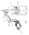
- the robotic assembly 8 of the invention comprises a robot of the four-axis type 9 and a return head 1.
- the four-axis robot equipped with an articulated arm is known per se, and used for example for the chains of automobile assembly; it has in addition to a distal end 10 articulated around a fourth axis A4, a first vertical axis A1 hinge and second A2 and third axes of articulation A3 horizontal.
- the distal end 10 of the four-axis type robot 9 is provided to receive a hinge 11 of the return head about the fourth axis A4.
- a hinge 11 consists on the one hand of a fixed plate 12 which can be fixed on the distal end 10, and on the other hand of a pivoting plate 13 adapted to pivot relative to the fixed plate 12 around the axis A4.
- the axis of rotation X of the drive shaft 4, which in principle forms the fifth axis of the robotic assembly, is preferably substantially perpendicular to the fourth axis A4.
- a compressed air outlet 15 located on the pivoting plate 13
- a rotary joint 16 it is possible to provide an electrical input 17, on the turntable fixed 12, connected to an electrical output 18, located on the turntable 13, using the rotating joints 19 and 20.
- the incorporation of electrical and / or pneumatic circuits in the hinge 11 allows avoid the presence of cables which impose constraints and may hinder rotations.
- the electrical connections passing through the hinge 11 serve in particular to power the motor 3 and possibly the sensors.
- a robotic assembly 8 as previously described may, in particular, capture and extract a block of molds at the top of a stack of a set of mold blocks with the gripper 6.
- This operation which corresponds to the partial transfer of the mold block from a stack to a second place, is usually called unstacking.
- the motor 3 of the return head 1 of the robotic assembly 8 causes the return of the block of molds, following a rotation of 180 ° around the X axis
- the part of the device constituted by the four-axis robot continues the transfer to the second place, for example, a stack intended to receive returned mold blocks. In the latter case, we are talking about a stacking step.
- Such a robotized assembly 8 thus makes it possible, thanks to its operating mode, and its simple and robust design, to carry out the operations of returning and transferring the blocks simultaneously. It is possible to combine different actions simultaneously or that these actions are partially superimposed over time. Thus, it is in particular possible to program the robotic assembly 8 so that it proceeds with the return operation during unstacking and / or stacking.
- the return head of the robotized assembly 8 can be controlled independently of the rest of the assembly, unlike the six-axis robot of the prior art where the control members are integrally managed by the control software. In this way, the operator has the possibility of acting, on the one hand, on the programming of the four-axis robot control devices, and on the other hand, independently but synchronously, on the programming of the tasks. of returns.
- Such a configuration offers a large number of adjustment possibilities, and makes it possible to select the most advantageous combinations in terms of duration and trajectory. All this reduces cycle times and increases production rates.
- the present invention is not limited to the embodiments described and shown, provided as simple examples.
- the invention can be generalized to a robot of more than four axes, such as a six-axis robot, on which certain axes are neutralized so as to keep only four axes, and consequently, to make operate such a robot as a four-axis.
- the skilled person of robotics knows how to make such changes.
Landscapes
- Engineering & Computer Science (AREA)
- Life Sciences & Earth Sciences (AREA)
- Robotics (AREA)
- Mechanical Engineering (AREA)
- Animal Husbandry (AREA)
- Environmental Sciences (AREA)
- Manipulator (AREA)
Description
- La présente invention se rapporte à un ensemble robotisé pour la retourne et le transfert d'un ensemble de préparations alimentaires et à un procédé mettant en oeuvre un tel ensemble robotisé.
- Au cours de leur fabrication, certains aliments tels que les fromages subissent différentes étapes de transformation. Certaines de ces étapes nécessitent le retournement des produits alimentaires, on citera par exemple dans le cas des fromages, les étapes de coagulation, de moulage, d'égouttage ou d'affinage. Pour réaliser une telle opération de retournement, différentes possibilités sont connues.
- On connait par exemple le retournement manuel. Celui-ci nécessite l'intervention d'un opérateur sur le poste, et étant donné qu'il ne permet que de petites cadences de production, il est quasiment exclusivement réservé à la fabrication de fromages très fragiles dont la préparation demande le plus grand soin.
- Il est également connu de procéder au retournement à l'aide d'un retourneur. La demande
FR 2 807 918 - La demanderesse a également mis au point un robot dit « cartésien » pour le retournement de plateaux de moule. Un tel robot comprend un chariot monté coulissant sur un support vertical, un bras monté articulé dans un plan horizontal par rapport à ce chariot, et une tête de retourne montée pivotante autour d'un axe horizontal par rapport à ce bras.
- Ce robot « cartésien » de la technique antérieure, cité par exemple dans le document XP002546657 « Mécanisation : l'attrait des robots », et visible sur le site Internet de la demanderesse (voir la page 2 du document www.tecnal.fr/upload/tecnal%20INFO%20N%C2%B0%2019.pdf), est un robot à deux axes + un axe de retourne, convenant à des utilisations limitées (typiquement : empilage/dépilage/retourne individuelle à partir d'une pile d'objet).
- Face à la demande sans cesse croissante de production et de conditionnement en grande série d'aliments, il est important de gagner en efficacité sur toutes les étapes depuis la réception des matières premières jusqu'à l'élaboration du produit fini. Dans ce cadre, on a de plus en plus en plus recours à des robots très sophistiqués, aux possibilités de déplacement pratiquement illimitées.
- Dans le cas des fromages, on a ainsi recours à l'utilisation de robots polyarticulés six axes, (analogues à ceux utilisés dans les chaînes de montage d'automobiles), qui permettent la retourne des fromages ainsi que toute une gamme de mouvements très complexes.
- L'un des inconvénients des robots six axes tient en particulier à leur mode de fonctionnement. Les tâches effectuées par ces robots sont gérées par un logiciel fourni avec le robot, de sorte que l'opérateur ne peut pas maîtriser tous les paramètres, et notamment il ne peut pas influer sur la vitesse de retourne. Ceci provoque une durée de temps de cycle, c'est-à-dire une durée séparant la répétition de deux actions similaires par le robot, souvent trop longue et incompatible avec des cadences de production élevées.
- Aussi, ces robots six axes sont pilotés par des programmes qui limitent considérablement les possibilités de déplacement du bras articulé du robot, parce qu'elles interdisent certaines configurations, comme celles qui présentent un alignement du quatrième axe avec le sixième axe.
- De plus, le couple et la vitesse de rotation autour du sixième axe sont souvent insuffisants pour la manutention d'objets lourds. Ainsi, les robots six axes ne permettent pas toujours de garantir un niveau de fiabilité compatible avec des cadences élevées, tout en respectant les normes de fabrication imposées.
- La présente invention vise à éviter les inconvénients précités et à améliorer les dispositifs du domaine de la robotique de l'art antérieur, notamment pour le retournement de préparations fromagères.
- A cet effet, l'invention a pour objet selon un premier aspect un ensemble robotisé pour le retournement et le transfert, d'un premier endroit vers un second endroit, d'au moins un ensemble de préparations alimentaires, tel qu'un bloc de moules à fromage, comprenant :
- un robot de type quatre axes qui comprend un socle et un bras ;
- une tête de retourne rapportée sur une extrémité distale du bras.
- Un tel ensemble robotisé est de conception simple, est robuste et offre un couple compatible avec le déplacement d'objets lourds. D'autre part, l'association de la tête de retourne avec le robot de type quatre axes dont la morphologie et le fonctionnement sont présentés en détail dans la suite de la présente description, confère une liberté de mouvements compatible notamment avec l'accomplissement simultané de rotations et de translations.
- On notera que le « premier endroit » et le « deuxième endroit » susmentionnés peuvent éventuellement être identiques.
- Le terme « robot de type quatre axes », au sens de la présente invention, inclut non seulement les robots munis de quatre axes, mais également tout robot de plus de quatre axes dont des axes ont été neutralisés, c'est-à-dire maintenus immobiles, afin qu'ils fonctionnent comme des robots avec quatre axes pendant les étapes de retourne.
- De tels robots peuvent éventuellement effectuer des tâches avec tous leurs axes opérationnels, c'est-à-dire non neutralisés, pendant les étapes de transfert sans retourne. L'homme du métier sait comment faire de telles modifications pour faire fonctionner un robot de plus de quatre axes, au moins en partie, comme un robot quatre axes.
- Le terme « rapportée » concernant la tête de retourne signifie qu'une tête de retourne spécifique, conçue indépendamment du robot et ne faisant donc pas partie de celui-ci, est fixée à l'extrémité du robot.
- Un tel ensemble robotisé permet de faire du temps masqué. Pendant le retournement des préparations alimentaires, d'autres opérations sont dès lors réalisables par l'ensemble robotisé en simultané. Ceci réduit considérablement les temps de cycle et améliore les cadences de production. Le fonctionnement d'un tel dispositif est davantage expliqué dans la suite de la présente description, et plus particulièrement dans les passages se rapportant au procédé associé au fonctionnement du présent ensemble robotisé.
- Suivant d'autres caractéristiques optionnelles de l'ensemble robotisé au sens de la présente invention :
- l'articulation de l'extrémité distale comprend au moins un joint tournant ;
- au moins un desdits joints tournants est traversé par un des éléments sélectionné parmi un circuit d'air comprimé et un circuit électrique ;
- la tête de retourne comprend : un châssis ; un moteur contenant un rotor et un stator ; un arbre d'entraînement monté en rotation autour d'un axe de retournement par liaison avec le rotor du moteur ; et un préhenseur monté à l'une des extrémités de l'arbre d'entraînement ;
- l'axe de l'articulation de l'extrémité distale est sensiblement perpendiculaire à l'axe de retournement ;
- ledit moteur est un moteur électrique ;
- ledit préhenseur est muni d'au moins un capteur pour détecter la position d'au moins un ensemble de préparations alimentaires ;
- ledit préhenseur comporte au moins l'un des éléments sélectionné parmi un vérin pneumatique et un actionneur électrique ;
- ledit arbre d'entraînement est creux ;
- ledit arbre d'entraînement creux est traversé par au moins un des éléments sélectionné parmi un circuit d'air comprimé et un circuit électrique ;
- Selon un deuxième aspect, l'invention a pour objet un procédé de retournement et de transfert d'un premier endroit vers un second endroit d'au moins un ensemble de préparations alimentaires, tel qu'un bloc de moules à fromage, mettant en oeuvre l'un des modes de réalisation d'ensemble robotisé tel que décrit précédemment, dans lequel l'ensemble robotisé effectue les opérations suivantes :
- (a)- le robot approche ladite tête de retourne de l'ensemble de préparations alimentaires localisées audit premier endroit ;
- (b)- ledit préhenseur saisit ledit ensemble ;
- (c)- ladite tête retourne ledit ensemble suivant une rotation déterminée autour dudit deuxième axe, par exemple de 180° ;
- (d)- le robot transfère ledit ensemble audit second endroit ; et l'étape (c) s'effectue au moins en partie pendant l'étape (d).
- L'ensemble robotisé au sens de la présente invention effectue des opérations de retourne d'au moins un ensemble de préparations alimentaires, par exemple de préparations fromagères, et peut assurer le transfert de l'ensemble à un emplacement différent du lieu où le robot effectue la préhension préalable à la retourne.
- Le robot de l'invention réalise la retourne, au moins en partie, pendant le mouvement de transfert, permettant ainsi de réduire le temps de cycle, et par suite, participant à l'augmentation des cadences de production.
- D'autres caractéristiques et avantages de l'invention apparaîtront à la lumière de la description qui va suivre en référence au figures annexées, dans lesquelles :
- la
figure 1 représente, en vue de détail, une coupe de profil de la partie basse de la tête de retourne ; - la
figure 2 représente une vue de côté de l'ensemble robotisé de l'invention ; - la
figure 3 représente, en vue de détail, une coupe de profil de l'articulation de la tête de retourne. - Le terme « endroit » au sens de la présente invention signifie le lieu où s'effectue la préhension du bloc de préparation alimentaires, ou la dépose de ce bloc suite aux opérations de retourne. Il peut s'agir d'un lieu de préhension ou de dépose situé sur un convoyeur d'amenée d'un ensemble de préparations alimentaires. Le terme « endroit » englobe également le sommet d'une pile de préparations alimentaires, tel que le haut d'une pile de bloc de moules à fromage.
- Le terme « bloc de moules » englobe notamment un plateau avec un ensemble de moules alimentaires disposés sur toute sa surface.
- Le terme « transfert » au sens de la présente invention signifie un déplacement global d'un premier endroit point vers un deuxième endroit, étant noté que ces deux endroits peuvent être identiques (retour au point de départ).
- La
figure 1 représente une vue en coupe d'un mode de réalisation de tête de retourne 1, avec un châssis 2 sur lequel est monté un moteur 3, de préférence un moteur électrique. Le moteur 3 est accouplé à un arbre d'entraînement 4, qui peut présenter une cavité 5. L'axe principal Y du châssis 2, représenté sur lafigure 1 suivant la direction verticale, peut être sensiblement perpendiculaire à l'axe de rotation X de l'arbre d'entraînement 4, représenté sur lafigure 1 suivant la direction horizontale. A l'extrémité la plus distale de la tête de retourne 1, l'arbre 4 est muni d'un préhenseur 6 pour saisir des ensembles de préparations alimentaires. - Le préhenseur 6 peut évenventuellement être équipé d'au moins un capteur, non représenté, destiné à indiquer la présence d'un des éléments à saisir par le préhenseur. L'homme du métier de la robotique sait comment placer de tels capteurs en fonction des systèmes de traitement de données de l'état de l'art. Il sait également quel dispositif de commande utiliser en connection avec un tel système de traitement des données transmises par le capteur.
- Typiquement, les données acquises par le capteur sont transmises au travers d'un circuit électrique à un système de traitement de données, et lorsqu'il y a détection de la présence d'un élément à saisir en vis-à-vis du préhenseur 6, un dispositif de commande ordonne la préhension.
- La préhension peut être commandée au travers d'un circuit pneumatique relié à un vérin, non représenté, du préhenseur.
- La cavité 5, éventuellement ménagée dans l'arbre 4, est destinée à recevoir, le cas échéant, un circuit électrique et/ou un circuit pneumatique. L'insertion d'au moins l'un de ces deux circuits se fait, par exemple, au travers de joints tournants tel que le joint tournant 7. L'incorporation des circuits électrique et/ou pneumatique dans la structure permet d'éviter la présence de câbles qui imposent des contraintes sur les axes, en particulier pendant les rotations.
- Comme illustré à la
figure 2 , l'ensemble robotisé 8 de l'invention comprend un robot de type quatre axes 9 et une tête de retourne 1. Le robot de type quatre axes équipé d'un bras articulé est connu en soi, et utilisé par exemple pour les chaînes de montage d'automobiles ; il présente en plus d'une extrémité distale 10 articulée autour d'un quatrième axe A4, un premier axe d'articulation A1 vertical et, des seconds A2 et troisièmes axes d'articulation A3 horizontaux. - Selon un mode de réalisation particulier de l'invention, l'extrémité distale 10 du robot de type quatre axes 9 est prévue pour recevoir une articulation 11 de la tête de retourne autour du quatrième axe A4. Une telle articulation 11 est constituée d'une part d'une platine fixe 12 qui peut être fixée sur l'extrémité distale 10, et d'autre part d'une platine pivotante 13 apte à pivoter par rapport à la platine fixe 12 autour de l'axe A4. L'axe de rotation X de l'arbre d'entrainement 4, qui forme en principe le cinquième axe de l'ensemble robotisé, est de préférence sensiblement perpendiculaire au quatrième axe A4.
- Il peut également être prévu, comme représenté à la
figure 3 , une entrée d'air comprimé 14, sur la platine fixe 12, reliée à une sortie d'air comprimé 15, située sur la platine pivotante 13, à l'aide d'un joint tournant 16. De la même manière, on peut prévoir une entrée électrique 17, sur la platine fixe 12, reliée à une sortie électrique 18, située sur la platine pivotante 13, à l'aide des joints tournants 19 et 20. De cette façon, l'incorporation des circuits électrique et/ou pneumatique dans l'articulation 11 permet d'éviter la présence de câbles qui imposent des contraintes et risquent de gêner les rotations. Les connexions électriques qui transitent par l'articulation 11 servent notamment à alimenter le moteur 3 et éventuellement les capteurs. - Un ensemble robotisé 8 tel que précedemment décrit peut, en particulier, saisir et extraire un bloc de moules au sommet d'une pile d'un ensemble de blocs de moule avec le préhenseur 6. Cette opération qui correspond au transfert partiel du bloc de moule d'une pile vers un deuxième endroit, est usellement dénommée le dépilage. Après avoir commencé à dépiler et au cours du transfert du bloc de moules, le moteur 3 de la tête de retourne 1 de l'ensemble robotisé 8 provoque la retourne du bloc de moules, suivant une rotation de 180° autour de l'axe X. Pendant cette opération de retourne, la partie du dispositif constitué par le robot quatre axes poursuit le transfert vers le deuxième endroit, par exemple, une pile destinée à recevoir des blocs de moules retournés. Dans ce dernier cas, on parle d'une étape d'empilage.
- Un tel ensemble robotisé 8 permet donc, grâce à son mode de fonctionnement, et à sa conception simple et robuste, d'effectuer les opérations de retourne et de transfert des blocs en simultané. Il est possible de cumuler différentes actions en simultané ou que ces actions soient partiellement superposées dans le temps. Ainsi, il est notamment possible de programmer l'ensemble robotisé 8 afin qu'il procède à l'opération de retourne au cours du dépilage et/ou de l'empilage.
- La tête de retourne de l'ensemble robotisé 8 peut être commandée indépendamment du reste de l'ensemble, contrairement au robot six axes de l'art antérieur où les organes de commande sont intégralement gérés par le logiciel de pilotage. De cette manière, l'opérateur a la possibilité d'agir, d'une part, sur la programmation des dispositifs de commande du robot de type quatre axes, et d'autre part, de manière indépendante mais synchronisée, sur la programmation des tâches de retourne. Une telle configuration offre un nombre important de possibilités de réglage, et, permet de sélectionner les combinaisons les plus avantageuses en terme de durée et de trajectoire. Tout ceci permet de réduire les temps de cycle et d'augmenter les cadences de production.
- Bien entendu, la présente invention n'est nullement limitée aux modes de réalisation décrits et représentés, fournis à titre de simples exemples. C'est ainsi que l'on peut généraliser l'invention à un robot de plus de quatre axes, tel qu'un robot six axes, sur lequel on neutralise certains axes de manière à ne garder que quatre axes, et par suite, faire fonctionner un tel robot comme un quatre axes. L'homme du métier de la robotique sait comment effectuer de telles modifications.
Claims (11)
- Ensemble robotisé (8) pour le retournement et le transfert, d'un premier endroit vers un second endroit, d'au moins un ensemble de préparations alimentaires, tel qu'un bloc de moules à fromage comprenant :- un robot de type quatre axes (9) qui comprend un socle et un bras ;- une tête de retourne (1) rapportée sur une extrémité distale (10) du bras.
- Ensemble robotisé (8) selon la revendication 1, dans lequel l'articulation de l'extrémité distale (10) comprend au moins un joint tournant (16, 19, 20).
- Ensemble robotisé (8) selon la revendication 2, caractérisé en ce que au moins un desdits joints tournants (16, 19, 20) est traversé par un des éléments sélectionné parmi un circuit d'air comprimé et un circuit électrique.
- Ensemble robotisé (8) selon l'une quelconque des revendications précédentes, caractérisé en ce que la tête de retourne (1) comprend :- un châssis (2) ;- un moteur (3) contenant un rotor et un stator;- un arbre d'entraînement (4) monté en rotation autour d'un axe de retournement (X) par liaison avec le rotor du moteur (3) ; et- un préhenseur (6) monté à l'une des extrémités de l'arbre d'entraînement (4).
- Ensemble robotisé (8) selon la revendication 4, caractérisé en ce que l'axe de l'articulation de l'extrémité distale (A4) est sensiblement perpendiculaire audit axe de retournement (X).
- Ensemble robotisé (8) selon l'une des revendication 4 ou 5, caractérisé en ce que ledit moteur (3) est un moteur électrique.
- Ensemble robotisé (8) selon l'une quelconques des revendications 4 à 6, caractérisé en ce que ledit préhenseur (6) est muni d'au moins un capteur pour détecter la position d'au moins un ensemble de préparations alimentaires.
- Ensemble robotisé (8) selon l'une quelconque quelconques des revendications 4 à 7, caractérisé en ce que ledit préhenseur (6) comporte au moins l'un des éléments sélectionné parmi un vérin pneumatique et un actionneur électrique.
- Ensemble robotisé (8) selon l'une quelconque des revendications 4 à 8, caractérisé en ce que ledit arbre d'entraînement (4) est creux.
- Ensemble robotisé (8) selon la revendication 9, caractérisé en ce que ledit arbre d'entraînement (4) creux est traversé par au moins un des éléments sélectionné parmi un circuit d'air comprimé et un circuit électrique.
- Procédé de retournement et de transfert d'un premier endroit vers un second endroit d'au moins un ensemble de préparations alimentaires, tel qu'un bloc de moules à fromage, mettant en oeuvre un ensemble robotisé (8) selon l'une quelconque des revendications 4 à 10, dans lequel l'ensemble robotisé (8) effectue les opérations suivantes :(a)- le robot (9) approche ladite tête de retourne (1) de l'ensemble de préparations alimentaires localisées audit premier endroit ;(b)- ledit préhenseur (6) saisit ledit ensemble ;(c)- ladite tête (1) retourne ledit ensemble de retournement suivant une rotation déterminée autour dudit axe de retournement (X), par exemple de 180° ;(d)- le robot (9) transfère ledit ensemble audit second endroit ; et l'étape (c) s'effectue au moins en partie pendant l'étape (d).
Applications Claiming Priority (2)
| Application Number | Priority Date | Filing Date | Title |
|---|---|---|---|
| FR0901036A FR2942736A1 (fr) | 2009-03-06 | 2009-03-06 | Ensemble robotise pour le retournement de blocs de moules a fromage |
| PCT/FR2010/050296 WO2010100362A1 (fr) | 2009-03-06 | 2010-02-19 | Ensemble robotise pour le retournement de blocs de moules a fromage |
Publications (2)
| Publication Number | Publication Date |
|---|---|
| EP2403690A1 EP2403690A1 (fr) | 2012-01-11 |
| EP2403690B1 true EP2403690B1 (fr) | 2013-05-29 |
Family
ID=41058533
Family Applications (1)
| Application Number | Title | Priority Date | Filing Date |
|---|---|---|---|
| EP10710077.8A Not-in-force EP2403690B1 (fr) | 2009-03-06 | 2010-02-19 | Ensemble robotise pour le retournement de blocs de moules a fromage |
Country Status (3)
| Country | Link |
|---|---|
| EP (1) | EP2403690B1 (fr) |
| FR (1) | FR2942736A1 (fr) |
| WO (1) | WO2010100362A1 (fr) |
Families Citing this family (9)
| Publication number | Priority date | Publication date | Assignee | Title |
|---|---|---|---|---|
| CN102267134B (zh) * | 2011-07-12 | 2013-12-25 | 浙江万丰摩轮有限公司 | 一种多功能通用机器人 |
| CN103029123B (zh) * | 2012-12-22 | 2015-04-01 | 浙江万丰科技开发有限公司 | 轻型六轴通用机器人 |
| CN105537899A (zh) * | 2016-03-02 | 2016-05-04 | 戴毅 | 机器人辅助电机定子搬运系统 |
| CN106671072A (zh) * | 2017-02-15 | 2017-05-17 | 昆山威创自动化科技有限公司 | 四轴码垛机器人 |
| CN108748122A (zh) * | 2018-06-29 | 2018-11-06 | 平湖市浩鑫塑胶有限公司 | 一种塑料瓶的夹持移动机构 |
| CN111645237B (zh) * | 2020-03-12 | 2022-04-08 | 海安迪斯凯瑞探测仪器有限公司 | 一种合模机器人系统 |
| CN114763219A (zh) * | 2021-01-11 | 2022-07-19 | 颍上县郭氏宝发米业有限公司 | 一种粮食收购站用搬运装置 |
| CN113829369A (zh) * | 2021-10-20 | 2021-12-24 | 河南睿辰机器人智能科技有限公司 | 一种多轴打磨机器人 |
| CN114303958B (zh) * | 2022-01-04 | 2022-12-02 | 安徽理工大学 | 基于混联机构的间距可调双夹爪式挤奶机器人 |
Family Cites Families (3)
| Publication number | Priority date | Publication date | Assignee | Title |
|---|---|---|---|---|
| FR2807918B1 (fr) | 2000-04-21 | 2003-07-04 | Equip Tech Ind Alimentaires | Retourneur avec galets mobiles sur surfaces de guidage |
| DE10347167B4 (de) * | 2003-10-06 | 2006-07-27 | Wilhelm Bahmüller Maschinenbau Präzisionswerkzeuge GmbH | Verfahren zur Entnahme und zum Ablegen eines Paketes, bestehend aus flachen Produkten |
| NL1028256C1 (nl) * | 2005-02-11 | 2006-08-14 | Bma Nederland B V | Overzetinrichting voor kazen. |
-
2009
- 2009-03-06 FR FR0901036A patent/FR2942736A1/fr not_active Withdrawn
-
2010
- 2010-02-19 WO PCT/FR2010/050296 patent/WO2010100362A1/fr not_active Ceased
- 2010-02-19 EP EP10710077.8A patent/EP2403690B1/fr not_active Not-in-force
Also Published As
| Publication number | Publication date |
|---|---|
| WO2010100362A1 (fr) | 2010-09-10 |
| FR2942736A1 (fr) | 2010-09-10 |
| EP2403690A1 (fr) | 2012-01-11 |
Similar Documents
| Publication | Publication Date | Title |
|---|---|---|
| EP2403690B1 (fr) | Ensemble robotise pour le retournement de blocs de moules a fromage | |
| EP0594476B1 (fr) | Grappin de manutention de charges, comme des sacs, palettiseur comportant un tel grappin, et procédé de palettisation | |
| EP1292431B1 (fr) | Bras de commande a deux branches en parallele | |
| FR3028441A1 (fr) | Dispositif et procede pour la manipulation d'articles tels que des emballages, des marchandises au detail ou autres | |
| FR2930472A1 (fr) | Robot manipulateur et commande associee pour un positionnement fin de l'extremite terminale | |
| FR2628661A1 (fr) | Appareil de manipulation pour machine a cintrer et procede de manipulation de pieces | |
| EP3145680A1 (fr) | Nacelle pour robot parallèle destiné à agir sur un objet | |
| FR2672836A1 (fr) | Dispositif d'articulation a structure parallele et appareils de transmission de mouvement a distance en faisant application. | |
| FR2658744A1 (fr) | Installation a presse de cintrage. | |
| EP4054804B1 (fr) | Articulation à trois degrés de liberté pour un robot et procédé de commande correspondant | |
| EP1934122B1 (fr) | Procede de chargement automatique et sequentiel d'objets et equipement correspondant | |
| EP3148753A1 (fr) | Manipulateur cobotique | |
| EP0544346A1 (fr) | Procédé de génération de trajectoire pour un système robotisé | |
| TW201914786A (zh) | 具自鎖功能的自適應夾爪機構 | |
| FR2739801A1 (fr) | Perfectionnements aux manipulateurs plans a trajectoire figee ou programmable a tres haute cadence | |
| EP2741893B1 (fr) | Procédé de commande d'un automate à actionnement parallèle redondant, dispositif de commande associé et automate | |
| EP3256291B1 (fr) | Station de dépôt d'un cordon de matière sur un couvercle et/ou un fond | |
| FR2880575A1 (fr) | Robot parallele incluant des moyens de compensation de charge | |
| FR2525147A1 (fr) | Appareil pour charger et pour decharger des presses industrielles | |
| FR2489275A1 (fr) | Transporteur du type dit " poutre marcheuse " | |
| FR2919515A1 (fr) | Dispositif articule a pantographes | |
| WO2026078077A1 (fr) | Robot et procede de commande adaptes pour reorienter un objet saisi par le robot | |
| FR3133930A1 (fr) | Systèmes et procédés de commande hybride position force d’un robot industriel | |
| WO2012110723A1 (fr) | Outil de manipulation de produits | |
| FR2505238A1 (fr) | Moyen de transfert de pieces du type robot a double bras |
Legal Events
| Date | Code | Title | Description |
|---|---|---|---|
| PUAI | Public reference made under article 153(3) epc to a published international application that has entered the european phase |
Free format text: ORIGINAL CODE: 0009012 |
|
| 17P | Request for examination filed |
Effective date: 20110812 |
|
| AK | Designated contracting states |
Kind code of ref document: A1 Designated state(s): AT BE BG CH CY CZ DE DK EE ES FI FR GB GR HR HU IE IS IT LI LT LU LV MC MK MT NL NO PL PT RO SE SI SK SM TR |
|
| DAX | Request for extension of the european patent (deleted) | ||
| GRAP | Despatch of communication of intention to grant a patent |
Free format text: ORIGINAL CODE: EPIDOSNIGR1 |
|
| GRAS | Grant fee paid |
Free format text: ORIGINAL CODE: EPIDOSNIGR3 |
|
| GRAA | (expected) grant |
Free format text: ORIGINAL CODE: 0009210 |
|
| AK | Designated contracting states |
Kind code of ref document: B1 Designated state(s): AT BE BG CH CY CZ DE DK EE ES FI FR GB GR HR HU IE IS IT LI LT LU LV MC MK MT NL NO PL PT RO SE SI SK SM TR |
|
| REG | Reference to a national code |
Ref country code: GB Ref legal event code: FG4D Free format text: NOT ENGLISH |
|
| REG | Reference to a national code |
Ref country code: CH Ref legal event code: EP |
|
| REG | Reference to a national code |
Ref country code: AT Ref legal event code: REF Ref document number: 614064 Country of ref document: AT Kind code of ref document: T Effective date: 20130615 |
|
| REG | Reference to a national code |
Ref country code: IE Ref legal event code: FG4D Free format text: LANGUAGE OF EP DOCUMENT: FRENCH |
|
| REG | Reference to a national code |
Ref country code: DE Ref legal event code: R096 Ref document number: 602010007337 Country of ref document: DE Effective date: 20130725 |
|
| REG | Reference to a national code |
Ref country code: AT Ref legal event code: MK05 Ref document number: 614064 Country of ref document: AT Kind code of ref document: T Effective date: 20130529 |
|
| REG | Reference to a national code |
Ref country code: LT Ref legal event code: MG4D |
|
| PG25 | Lapsed in a contracting state [announced via postgrant information from national office to epo] |
Ref country code: ES Free format text: LAPSE BECAUSE OF FAILURE TO SUBMIT A TRANSLATION OF THE DESCRIPTION OR TO PAY THE FEE WITHIN THE PRESCRIBED TIME-LIMIT Effective date: 20130909 Ref country code: NO Free format text: LAPSE BECAUSE OF FAILURE TO SUBMIT A TRANSLATION OF THE DESCRIPTION OR TO PAY THE FEE WITHIN THE PRESCRIBED TIME-LIMIT Effective date: 20130829 Ref country code: SE Free format text: LAPSE BECAUSE OF FAILURE TO SUBMIT A TRANSLATION OF THE DESCRIPTION OR TO PAY THE FEE WITHIN THE PRESCRIBED TIME-LIMIT Effective date: 20130529 Ref country code: LT Free format text: LAPSE BECAUSE OF FAILURE TO SUBMIT A TRANSLATION OF THE DESCRIPTION OR TO PAY THE FEE WITHIN THE PRESCRIBED TIME-LIMIT Effective date: 20130529 Ref country code: AT Free format text: LAPSE BECAUSE OF FAILURE TO SUBMIT A TRANSLATION OF THE DESCRIPTION OR TO PAY THE FEE WITHIN THE PRESCRIBED TIME-LIMIT Effective date: 20130529 Ref country code: GR Free format text: LAPSE BECAUSE OF FAILURE TO SUBMIT A TRANSLATION OF THE DESCRIPTION OR TO PAY THE FEE WITHIN THE PRESCRIBED TIME-LIMIT Effective date: 20130830 Ref country code: IS Free format text: LAPSE BECAUSE OF FAILURE TO SUBMIT A TRANSLATION OF THE DESCRIPTION OR TO PAY THE FEE WITHIN THE PRESCRIBED TIME-LIMIT Effective date: 20130929 Ref country code: PT Free format text: LAPSE BECAUSE OF FAILURE TO SUBMIT A TRANSLATION OF THE DESCRIPTION OR TO PAY THE FEE WITHIN THE PRESCRIBED TIME-LIMIT Effective date: 20130930 Ref country code: FI Free format text: LAPSE BECAUSE OF FAILURE TO SUBMIT A TRANSLATION OF THE DESCRIPTION OR TO PAY THE FEE WITHIN THE PRESCRIBED TIME-LIMIT Effective date: 20130529 Ref country code: SI Free format text: LAPSE BECAUSE OF FAILURE TO SUBMIT A TRANSLATION OF THE DESCRIPTION OR TO PAY THE FEE WITHIN THE PRESCRIBED TIME-LIMIT Effective date: 20130529 |
|
| REG | Reference to a national code |
Ref country code: NL Ref legal event code: VDEP Effective date: 20130529 |
|
| PG25 | Lapsed in a contracting state [announced via postgrant information from national office to epo] |
Ref country code: BG Free format text: LAPSE BECAUSE OF FAILURE TO SUBMIT A TRANSLATION OF THE DESCRIPTION OR TO PAY THE FEE WITHIN THE PRESCRIBED TIME-LIMIT Effective date: 20130829 Ref country code: PL Free format text: LAPSE BECAUSE OF FAILURE TO SUBMIT A TRANSLATION OF THE DESCRIPTION OR TO PAY THE FEE WITHIN THE PRESCRIBED TIME-LIMIT Effective date: 20130529 Ref country code: HR Free format text: LAPSE BECAUSE OF FAILURE TO SUBMIT A TRANSLATION OF THE DESCRIPTION OR TO PAY THE FEE WITHIN THE PRESCRIBED TIME-LIMIT Effective date: 20130529 |
|
| PG25 | Lapsed in a contracting state [announced via postgrant information from national office to epo] |
Ref country code: LV Free format text: LAPSE BECAUSE OF FAILURE TO SUBMIT A TRANSLATION OF THE DESCRIPTION OR TO PAY THE FEE WITHIN THE PRESCRIBED TIME-LIMIT Effective date: 20130529 |
|
| PG25 | Lapsed in a contracting state [announced via postgrant information from national office to epo] |
Ref country code: CZ Free format text: LAPSE BECAUSE OF FAILURE TO SUBMIT A TRANSLATION OF THE DESCRIPTION OR TO PAY THE FEE WITHIN THE PRESCRIBED TIME-LIMIT Effective date: 20130529 Ref country code: SK Free format text: LAPSE BECAUSE OF FAILURE TO SUBMIT A TRANSLATION OF THE DESCRIPTION OR TO PAY THE FEE WITHIN THE PRESCRIBED TIME-LIMIT Effective date: 20130529 Ref country code: DK Free format text: LAPSE BECAUSE OF FAILURE TO SUBMIT A TRANSLATION OF THE DESCRIPTION OR TO PAY THE FEE WITHIN THE PRESCRIBED TIME-LIMIT Effective date: 20130529 Ref country code: EE Free format text: LAPSE BECAUSE OF FAILURE TO SUBMIT A TRANSLATION OF THE DESCRIPTION OR TO PAY THE FEE WITHIN THE PRESCRIBED TIME-LIMIT Effective date: 20130529 |
|
| PG25 | Lapsed in a contracting state [announced via postgrant information from national office to epo] |
Ref country code: IT Free format text: LAPSE BECAUSE OF FAILURE TO SUBMIT A TRANSLATION OF THE DESCRIPTION OR TO PAY THE FEE WITHIN THE PRESCRIBED TIME-LIMIT Effective date: 20130529 Ref country code: RO Free format text: LAPSE BECAUSE OF FAILURE TO SUBMIT A TRANSLATION OF THE DESCRIPTION OR TO PAY THE FEE WITHIN THE PRESCRIBED TIME-LIMIT Effective date: 20130529 Ref country code: NL Free format text: LAPSE BECAUSE OF FAILURE TO SUBMIT A TRANSLATION OF THE DESCRIPTION OR TO PAY THE FEE WITHIN THE PRESCRIBED TIME-LIMIT Effective date: 20130529 |
|
| PLBE | No opposition filed within time limit |
Free format text: ORIGINAL CODE: 0009261 |
|
| STAA | Information on the status of an ep patent application or granted ep patent |
Free format text: STATUS: NO OPPOSITION FILED WITHIN TIME LIMIT |
|
| 26N | No opposition filed |
Effective date: 20140303 |
|
| REG | Reference to a national code |
Ref country code: DE Ref legal event code: R097 Ref document number: 602010007337 Country of ref document: DE Effective date: 20140303 |
|
| BERE | Be: lapsed |
Owner name: EQUIPEMENTS TECHNIQUES DES INDUSTRIES ALIMENTAIRE Effective date: 20140228 |
|
| PG25 | Lapsed in a contracting state [announced via postgrant information from national office to epo] |
Ref country code: MC Free format text: LAPSE BECAUSE OF FAILURE TO SUBMIT A TRANSLATION OF THE DESCRIPTION OR TO PAY THE FEE WITHIN THE PRESCRIBED TIME-LIMIT Effective date: 20130529 Ref country code: LU Free format text: LAPSE BECAUSE OF FAILURE TO SUBMIT A TRANSLATION OF THE DESCRIPTION OR TO PAY THE FEE WITHIN THE PRESCRIBED TIME-LIMIT Effective date: 20140219 |
|
| REG | Reference to a national code |
Ref country code: CH Ref legal event code: PL |
|
| PG25 | Lapsed in a contracting state [announced via postgrant information from national office to epo] |
Ref country code: CH Free format text: LAPSE BECAUSE OF NON-PAYMENT OF DUE FEES Effective date: 20140228 Ref country code: LI Free format text: LAPSE BECAUSE OF NON-PAYMENT OF DUE FEES Effective date: 20140228 |
|
| REG | Reference to a national code |
Ref country code: IE Ref legal event code: MM4A |
|
| PG25 | Lapsed in a contracting state [announced via postgrant information from national office to epo] |
Ref country code: IE Free format text: LAPSE BECAUSE OF NON-PAYMENT OF DUE FEES Effective date: 20140219 Ref country code: BE Free format text: LAPSE BECAUSE OF NON-PAYMENT OF DUE FEES Effective date: 20140228 |
|
| REG | Reference to a national code |
Ref country code: FR Ref legal event code: PLFP Year of fee payment: 7 |
|
| PG25 | Lapsed in a contracting state [announced via postgrant information from national office to epo] |
Ref country code: MT Free format text: LAPSE BECAUSE OF FAILURE TO SUBMIT A TRANSLATION OF THE DESCRIPTION OR TO PAY THE FEE WITHIN THE PRESCRIBED TIME-LIMIT Effective date: 20130529 |
|
| PG25 | Lapsed in a contracting state [announced via postgrant information from national office to epo] |
Ref country code: SM Free format text: LAPSE BECAUSE OF FAILURE TO SUBMIT A TRANSLATION OF THE DESCRIPTION OR TO PAY THE FEE WITHIN THE PRESCRIBED TIME-LIMIT Effective date: 20130529 |
|
| PG25 | Lapsed in a contracting state [announced via postgrant information from national office to epo] |
Ref country code: CY Free format text: LAPSE BECAUSE OF FAILURE TO SUBMIT A TRANSLATION OF THE DESCRIPTION OR TO PAY THE FEE WITHIN THE PRESCRIBED TIME-LIMIT Effective date: 20130529 |
|
| PG25 | Lapsed in a contracting state [announced via postgrant information from national office to epo] |
Ref country code: HU Free format text: LAPSE BECAUSE OF FAILURE TO SUBMIT A TRANSLATION OF THE DESCRIPTION OR TO PAY THE FEE WITHIN THE PRESCRIBED TIME-LIMIT; INVALID AB INITIO Effective date: 20100219 |
|
| REG | Reference to a national code |
Ref country code: FR Ref legal event code: PLFP Year of fee payment: 8 |
|
| REG | Reference to a national code |
Ref country code: FR Ref legal event code: PLFP Year of fee payment: 9 |
|
| PG25 | Lapsed in a contracting state [announced via postgrant information from national office to epo] |
Ref country code: MK Free format text: LAPSE BECAUSE OF FAILURE TO SUBMIT A TRANSLATION OF THE DESCRIPTION OR TO PAY THE FEE WITHIN THE PRESCRIBED TIME-LIMIT Effective date: 20130529 |
|
| PGFP | Annual fee paid to national office [announced via postgrant information from national office to epo] |
Ref country code: GB Payment date: 20190320 Year of fee payment: 10 |
|
| PGFP | Annual fee paid to national office [announced via postgrant information from national office to epo] |
Ref country code: TR Payment date: 20190211 Year of fee payment: 10 |
|
| PGFP | Annual fee paid to national office [announced via postgrant information from national office to epo] |
Ref country code: DE Payment date: 20200117 Year of fee payment: 11 |
|
| PGFP | Annual fee paid to national office [announced via postgrant information from national office to epo] |
Ref country code: FR Payment date: 20200110 Year of fee payment: 11 |
|
| GBPC | Gb: european patent ceased through non-payment of renewal fee |
Effective date: 20200219 |
|
| PG25 | Lapsed in a contracting state [announced via postgrant information from national office to epo] |
Ref country code: GB Free format text: LAPSE BECAUSE OF NON-PAYMENT OF DUE FEES Effective date: 20200219 |
|
| REG | Reference to a national code |
Ref country code: DE Ref legal event code: R119 Ref document number: 602010007337 Country of ref document: DE |
|
| PG25 | Lapsed in a contracting state [announced via postgrant information from national office to epo] |
Ref country code: DE Free format text: LAPSE BECAUSE OF NON-PAYMENT OF DUE FEES Effective date: 20210901 Ref country code: FR Free format text: LAPSE BECAUSE OF NON-PAYMENT OF DUE FEES Effective date: 20210228 |
|
| PG25 | Lapsed in a contracting state [announced via postgrant information from national office to epo] |
Ref country code: TR Free format text: LAPSE BECAUSE OF NON-PAYMENT OF DUE FEES Effective date: 20200219 |