EP2404367B1 - Moteur à rotor double - Google Patents
Moteur à rotor double Download PDFInfo
- Publication number
- EP2404367B1 EP2404367B1 EP10712316.8A EP10712316A EP2404367B1 EP 2404367 B1 EP2404367 B1 EP 2404367B1 EP 10712316 A EP10712316 A EP 10712316A EP 2404367 B1 EP2404367 B1 EP 2404367B1
- Authority
- EP
- European Patent Office
- Prior art keywords
- electric motor
- housing
- motor according
- supports
- stator
- Prior art date
- Legal status (The legal status is an assumption and is not a legal conclusion. Google has not performed a legal analysis and makes no representation as to the accuracy of the status listed.)
- Active
Links
Images


Classifications
-
- H—ELECTRICITY
- H02—GENERATION; CONVERSION OR DISTRIBUTION OF ELECTRIC POWER
- H02K—DYNAMO-ELECTRIC MACHINES
- H02K16/00—Machines with more than one rotor or stator
- H02K16/02—Machines with one stator and two or more rotors
-
- H—ELECTRICITY
- H02—GENERATION; CONVERSION OR DISTRIBUTION OF ELECTRIC POWER
- H02K—DYNAMO-ELECTRIC MACHINES
- H02K1/00—Details of the magnetic circuit
- H02K1/06—Details of the magnetic circuit characterised by the shape, form or construction
- H02K1/12—Stationary parts of the magnetic circuit
- H02K1/18—Means for mounting or fastening magnetic stationary parts on to, or to, the stator structures
-
- H—ELECTRICITY
- H02—GENERATION; CONVERSION OR DISTRIBUTION OF ELECTRIC POWER
- H02K—DYNAMO-ELECTRIC MACHINES
- H02K1/00—Details of the magnetic circuit
- H02K1/06—Details of the magnetic circuit characterised by the shape, form or construction
- H02K1/12—Stationary parts of the magnetic circuit
- H02K1/20—Stationary parts of the magnetic circuit with channels or ducts for flow of cooling medium
-
- H—ELECTRICITY
- H02—GENERATION; CONVERSION OR DISTRIBUTION OF ELECTRIC POWER
- H02K—DYNAMO-ELECTRIC MACHINES
- H02K1/00—Details of the magnetic circuit
- H02K1/06—Details of the magnetic circuit characterised by the shape, form or construction
- H02K1/22—Rotating parts of the magnetic circuit
- H02K1/28—Means for mounting or fastening rotating magnetic parts on to, or to, the rotor structures
-
- H—ELECTRICITY
- H02—GENERATION; CONVERSION OR DISTRIBUTION OF ELECTRIC POWER
- H02K—DYNAMO-ELECTRIC MACHINES
- H02K3/00—Details of windings
- H02K3/04—Windings characterised by the conductor shape, form or construction, e.g. with bar conductors
- H02K3/24—Windings characterised by the conductor shape, form or construction, e.g. with bar conductors with channels or ducts for cooling medium between the conductors
-
- H—ELECTRICITY
- H02—GENERATION; CONVERSION OR DISTRIBUTION OF ELECTRIC POWER
- H02K—DYNAMO-ELECTRIC MACHINES
- H02K5/00—Casings; Enclosures; Supports
- H02K5/04—Casings or enclosures characterised by the shape, form or construction thereof
- H02K5/08—Insulating casings
-
- H—ELECTRICITY
- H02—GENERATION; CONVERSION OR DISTRIBUTION OF ELECTRIC POWER
- H02K—DYNAMO-ELECTRIC MACHINES
- H02K5/00—Casings; Enclosures; Supports
- H02K5/04—Casings or enclosures characterised by the shape, form or construction thereof
- H02K5/20—Casings or enclosures characterised by the shape, form or construction thereof with channels or ducts for flow of cooling medium
- H02K5/203—Casings or enclosures characterised by the shape, form or construction thereof with channels or ducts for flow of cooling medium specially adapted for liquids, e.g. cooling jackets
-
- H—ELECTRICITY
- H02—GENERATION; CONVERSION OR DISTRIBUTION OF ELECTRIC POWER
- H02K—DYNAMO-ELECTRIC MACHINES
- H02K9/00—Arrangements for cooling or ventilating
- H02K9/02—Arrangements for cooling or ventilating by ambient air flowing through the machine
- H02K9/04—Arrangements for cooling or ventilating by ambient air flowing through the machine having means for generating a flow of cooling medium
- H02K9/06—Arrangements for cooling or ventilating by ambient air flowing through the machine having means for generating a flow of cooling medium with fans or impellers driven by the machine shaft
-
- H—ELECTRICITY
- H02—GENERATION; CONVERSION OR DISTRIBUTION OF ELECTRIC POWER
- H02K—DYNAMO-ELECTRIC MACHINES
- H02K9/00—Arrangements for cooling or ventilating
- H02K9/19—Arrangements for cooling or ventilating for machines with closed casing and closed-circuit cooling using a liquid cooling medium, e.g. oil
-
- H—ELECTRICITY
- H02—GENERATION; CONVERSION OR DISTRIBUTION OF ELECTRIC POWER
- H02K—DYNAMO-ELECTRIC MACHINES
- H02K9/00—Arrangements for cooling or ventilating
- H02K9/22—Arrangements for cooling or ventilating by solid heat conducting material embedded in, or arranged in contact with, the stator or rotor, e.g. heat bridges
- H02K9/223—Heat bridges
-
- H—ELECTRICITY
- H02—GENERATION; CONVERSION OR DISTRIBUTION OF ELECTRIC POWER
- H02K—DYNAMO-ELECTRIC MACHINES
- H02K15/00—Processes or apparatus specially adapted for manufacturing, assembling, maintaining or repairing of dynamo-electric machines
- H02K15/12—Impregnating, moulding insulation, heating or drying of windings, stators, rotors or machines
-
- H—ELECTRICITY
- H02—GENERATION; CONVERSION OR DISTRIBUTION OF ELECTRIC POWER
- H02K—DYNAMO-ELECTRIC MACHINES
- H02K5/00—Casings; Enclosures; Supports
- H02K5/04—Casings or enclosures characterised by the shape, form or construction thereof
- H02K5/20—Casings or enclosures characterised by the shape, form or construction thereof with channels or ducts for flow of cooling medium
- H02K5/207—Casings or enclosures characterised by the shape, form or construction thereof with channels or ducts for flow of cooling medium with openings in the casing specially adapted for ambient air
-
- H—ELECTRICITY
- H02—GENERATION; CONVERSION OR DISTRIBUTION OF ELECTRIC POWER
- H02K—DYNAMO-ELECTRIC MACHINES
- H02K9/00—Arrangements for cooling or ventilating
- H02K9/22—Arrangements for cooling or ventilating by solid heat conducting material embedded in, or arranged in contact with, the stator or rotor, e.g. heat bridges
- H02K9/227—Heat sinks
Definitions
- the present invention relates to a double-rotor motor according to the preamble of claim 1.
- Double rotor engines are off EP 1879283 (Matsushita ) EP 1191673 (Denso ) and US 5260642 (Huss ) previously known.
- a stator structure in which two rotors with permanent magnets are connected to one another via a shaft. The rotors are driven by a stator wound with exciting coils.
- the stator is made in one piece and consists of inner and outer teeth with pole shoes and a tangential connecting web between the yoke legs.
- an excitation coil is wound in the circumferential direction, as shown in Fig. 8 of the EP 1879283 and in Fig. 38 of EP 1191673 is shown.
- the magnetic flux is generated tangentially in the connecting web.
- the magnetic flux is divided in the yoke teeth in two magnetic partial flows.
- One of the partial flows goes radially outward to the outer rotor and closes over the outer rotor and over the adjacent one Stator tooth radially inwards to the connecting bar.
- the second sub-flow leads radially inwards and closes over the inner rotor, and is guided radially outwards over the adjacent stator tooth and closes over the connecting web.
- EP 1191673 are different from the stator of the EP 1879283 the rotors are not connected to each other via a shaft. Instead, the relative rotor position of the outer and inner rotors is controlled via a control algorithm.
- the from the EP 1191673 and EP 1879283 known winding technique is disadvantageous.
- the tangential winding technique is on the one hand very complex, on the other hand, no good Kupferglalltex can be achieved with automated winding, since the covered by the pole pieces space during winding can be filled poorly.
- the magnetic flux is generated by the connecting web in the tangential direction and then deflected by 90 ° in the radial direction. This is unfavorable for the efficiency of the magnetic circuits and precludes the use of soft magnetic material with grain orientation.
- the object of the invention is to further develop a double-rotor motor such that a very good power density is achieved and cost-effective production is made possible.
- stator teeth which may advantageously have a double T-shape in cross section, i. radially outside and inside pole pieces have, first wound axially and then inserted into a rigid support structure which lies between the stator teeth.
- stator teeth can be connected to pins in the pole shoes with the housing.
- the stator has no tangential connecting webs. The magnetic flux is generated radially in this embodiment and closes over the outer rotor, the adjacent stator teeth and the inner rotor.
- the individual teeth are positioned, held and joined to form a stator by means of carrier or carrier elements which are fixed to the housing or connected to a fixed relative to the housing part.
- the carrier can be connected by force or positive engagement with the housing or the fixed relative to the housing part.
- the carriers it is also possible for the carriers to be integrally formed with the housing or the part arranged on the housing or molded onto it, in particular molded on it. It is also possible that one or more carriers are integrally formed with the housing or the housing fixed to the housing part arranged and the other carriers are attached as isolated parts on the housing or part.
- the supports are advantageously made of a plastic, e.g. Duroplast, manufactured.
- the plastic is advantageous high strength and can be reinforced by inserted reinforcing elements. It is also advantageous if fillers with good heat conducting properties are incorporated in the plastic.
- the carrier elements extend in the axial and radial direction between the adjacent stator teeth and excitation coils and are preferably designed in cross-section T-shaped or double-T-shaped, so that the Assembled stator achieved a very high rigidity for radial and tangential loads.
- the stator can preferably be cast with a good heat-conducting resin in order to further improve the heat conduction and to further increase the rigidity of the structure.
- the potting material also has the advantage that tolerances of the support elements are compensated.
- the housing is shaped such that the pole shoes of the individual teeth are in direct contact with the housing. So the heat output can be further improved.
- the plastic is e.g. has good heat conduction properties by adding fillers.
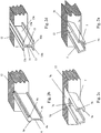
- Fig. 1 the stator cross-section of the motor structure according to the invention for three possible embodiments A, B and C of the stator and two possible rotor configurations is shown.
- the stator consists of isolated stator teeth 1 with pole shoes 1 a in the outer region and pole shoes 1 b in the inner region, which are wound with excitation coils 4.
- the motor has an outer rotor 3a equipped with permanent magnets 2a and an inner rotor 3b equipped with permanent magnets 2b, the stator teeth 1 being held in different carriers 5, 6 and 7 in embodiments A, B and C, respectively.
- the magnetic flux 8 closes over the stator tooth 1, the magnets 2a, the outer rotor 3a, the adjacent stator tooth 1 and the magnets 2b of the inner rotor 3b.
- an air gap 31 inside and outside.
- the outer rotor 3a and the inner rotor 3b is thin-walled and preferably made of a ferromagnetic material, so that the magnetic flux 9 both outside and inside via a housing part or insert 10, 10a, which may also be referred to as the return part, closes.
- the housing part or insert 10, 10a is made of ferromagnetic material.
- the stator teeth 1 are held in the embodiment A of the support structure by two plastic moldings 5, which have in the region of the inner and outer pole piece 1 a, 1 b for the respective stator tooth 1 bent down collar 5 a and 5 b and thus configured in cross-section U-shaped.
- the collars 5a, 5b each engage in a shoulder or depression 1c of the stator tooth 1 in the stator tooth.
- the pole piece 1a is thereby supported in the area 1d.
- the supports 5 are preferably made of high strength plastic or alternatively may be made of a non-ferromagnetic material such as stainless steel e.g. V2A, to minimize the influence of the magnetic circuit to be executed.
- the support element 6 is made in one piece between two adjacent stator teeth or yoke teeth 1 and has a cross-sectionally T-shaped structure which has corresponding paragraphs 6a in the outer region, in the contour or grooves of the stator teeth yoke teeth 1 engage, the stator teeth are pushed onto these paragraphs 6a.
- a third embodiment C of the support structure of the wound stator tooth is inserted into a one-piece support 7, which comprises the exciter coil 4 on both sides and is bent inwardly in the region of the outer and inner pole piece so that it is bent in a double U-shaped in cross-section and supports the pole pieces and forms a positive connection at least in the radial direction with the pole shoes.
- an air gap 11 is preferably provided, which in the embodiments A and C of the support structure radially between the Pole shoes of the stator teeth 1 extends.
- This air gap 11 is used as a cooling channel to further improve heat dissipation.
- a fan can be used for better cooling.
- FIG. 2a is the support structure A from FIG. 1 shown in perspective.
- the carriers 5 are either caulked, potted or injected into the housing 12.
- the collar 5c is made wider to improve the stiffening.
- Fig. 2b is the support structure B from Fig.1 shown in perspective.
- the carrier profile 6 is, as in the support structure A gem.
- Fig. 2a with the housing 12 caulked, welded, potted or injected or forms a part of the housing, which may be in particular a reworked die-cast housing with profile webs.
- the carrier 6 is formed in cross-section as a double-T-carrier, wherein on its collar in the axial direction extending paragraphs or collars 6a, 6b are formed, which serve to fix and support the retractable stator teeth.
- FIG. 2c is the support structure C from FIG. 1 shown in perspective.
- the carrier 7 has two inwardly directed collar 7a and 7b, on which the stator tooth 1, not shown, rests with its pole shoes 1a, 1b, and which engage in the pole piece.
- the carrier 7 is in this case preferably in one piece and has a bottom wall 7d and a connecting portion 7c.
- the carrier 7 comprises the exciter coil 4 completely and is connected to the housing 12. However, it is also possible to shed or inject the carrier 7 with in or on the housing 12.
- Figure 2d is a variant of the support structure A from FIG. 1 shown.
- the composite carrier 13 results in a double-T-carrier, which projects into the housing part 12 and is connected by means of potting or caulking with the housing.
- the bearing surfaces can be similar Fig. 4a be edited later.
- the contiguous Carriers 13 may of course also be manufactured as a single part by injection molding.
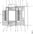
- Fig. 3a is a longitudinal section of the double rotor motor according to the invention with the in Fig. 1 and Fig. 2c executed support structure C shown.
- the bottom wall 7 d of the carrier 7 is connected to the housing 12.
- the outer rotor 3a and the inner rotor 3b can be made in one piece as shown. However, it is also possible to form the rotors 3a, 3b in several parts.
- the rotors 3a, 3b are connected to an output shaft 16, which are mounted in the housing via bearings 15a and 15b.
- Fig. 3b is the execution of the profile carrier structure of Fig. 2b executed in longitudinal section of the engine.
- the profile carrier 6 is connected to the housing 12, wherein the excitation coils 4 protrude into the housing 12.
- a cooling channel for water cooling can be provided in the housing 12, which improves the heat dissipation of the engine.
- the water channels may be expanded by being guided axially outwardly and the inner pole teeth axially inwardly back to the main water channel 18 via a U-tube 18a through the outer pole teeth.
- the support structure can be further reinforced on one side by a reinforcing ring 19, 19 a relative to the housing. In the reinforcing ring 19, 19 a, the otherwise free ends of the profile carrier 6 are based.
- the exciter coils 4 are encapsulated or encapsulated with the carrier 6 and the housing 12 by means of a potting compound or plastic injection molding compound 20.
- Figure 3c is the longitudinal section of the support structure according to the FIGS. 2a, 2b and 2d shown.
- the profile beams 5, 6, 13 are recessed in the housing 12 with their front ends 26a or protrude through the housing 12 and are frontally glued to the housing 12 with its front ends 26b, caulked or injected. It makes sense to provide 12 corresponding recesses in the housing, so that both the excitation coils 4 are recessed in the housing 12 and for the coil outlets 22 corresponding recesses are provided and a corresponding punched grid 23 can be attached to the coil contact on the housing 12. It is further provided that the pole pieces 1a and 1b are in direct contact with the housing 12 and in Housing 12 a corresponding paragraph 12 a is provided.
- FIG. 1 Shown in this figure is a multi-part rotor design.
- the rotor 3 is connected to a driver 25, which in turn is connected to a shaft 16.
- a fan 21 is provided to improve the cooling.
- the fan 21 is preferably integrated in the rotor 3.
- Shown in this figure is the inference principle, as in FIG. 1 represented and designated by the reference numeral 9.
- a ferromagnetic part 24 for example in the form of a punching plate or a tube inserted, via which the magnetic flux is closed.
- the engine according to the invention with large diameters of the inner and outer rotor creates a cavity in the engine.
- This can usefully be used for integration of a gear or spindle drive.
- the bearing or output shaft 16 for receiving a transmission, preferably a planetary gear, accordingly.
- the housing 12 and the receptacle must be designed accordingly.
- the integrated transmission motor according to the invention may then be e.g. be used as wheel hub drive.
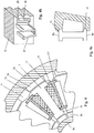
- FIGS. 4 to 4b is a variant of the profile carrier construction gem.
- Fig. 2b shown.
- the pole teeth 1a in the outer region 1e rest on a double-T-shaped profile carrier 27 and a small air gap 1f is provided for tolerance compensation.
- This solution can be produced by casting.
- FIG. 4a is the profile carrier 27 of FIG. 4 preferably only on the outer radius Ra and inner radius Ri post-processed. In the region of the stator tooth 1 e, a corresponding radius is provided, so that a precisely fitting contact is ensured. Since the stator teeth are produced stanzuniert, a very high accuracy of the cross-sectional contour of the stator teeth and air gaps can be achieved.
- the profile carrier 27 form part of the housing 12. In the housing 12 recesses 30 are provided for the exciter coils, not shown, as well as openings 29 for the electrical contact.
- FIGS. 5a and 5b show an embodiment in which the strength of the stator is increased.
- an outer reinforcing ring 32a and an inner reinforcing ring 32b are attached to the front side of the Polschuhformmaschine 1. These are mounted outside or inside the exciter coils 4.
- the outer dowel pin 33a and the inner dowel pin 33b are pressed by the Polschuhformteil 1 and frontally connected to the reinforcing rings 32a and 32b, preferably caulked.
- the dowel pins 33a and 33b are connected to the housing 12. This can be done by caulking at 34a or pressing in at 34b.
- the dowel pins 33a and 33b can absorb the tensile stresses that arise in the pole piece parts 1 due to, for example, radial forces.
- the heat dissipation is supported by a direct contact of the pole pieces 1a and 1b with the housing 12a.
- the pole pieces 1 are connected to their adjacent pole pieces.
- all the individual pole pieces 1 are combined into a composite, which can absorb the forces occurring better and is more stable overall.
- FIG. 5b is shown as an alternative to the reinforcing rings 32a and 32b, a one-piece reinforcing ring 32c, which engages around the coil end face. As a result, the overall strength can be further increased.
- the FIG. 6 shows an extension of the T-support structure 35.
- the carriers 35 are connected to an outer ring 35e as part of the injection molding or casting with casting resin over the areas 35s, which includes the outer poles 1a including the foundedstärkungsring 35e.
- This ring 35e is also at Small wall thickness very effective for stiffening under tangential load.
- both the outer and the inner yoke 1 a, 1 b are thin-walled by rings 35e and are connected to webs between the coils.
- Duroplast is preferably suitable for producing a thin wall thickness.
- the area E between the poles may optionally be made somewhat deeper for injection because of the formation of burrs.
- the coil space between the poles can be fully utilized, which increases the efficiency. With these measures, a high rigidity with good heat dissipation can be achieved, so that it is possible to realize a large-capacity motor with a small diameter and relatively long self-supporting coils.
- the FIG. 7 shows the double-T-beam 35 with a radially outer reinforcing member 37.
- the reinforcing member 37 may alternatively be arranged relative to the excitation coils 4 but also radially inward.
- outside and inside reinforcing elements 37 can be arranged and injected.
- the reinforcing element 37 is made of a poorly conductive metallic material, such as stainless steel, with cutouts 37a to reduce the current conductivity and thus the eddy current losses.
- the double-T-carrier 35 is produced as a separate plastic injection-molded part with injected reinforcing element 37 and then arranged on the housing 12, so that subsequently the stator teeth or yokes 1 can be pushed onto the carriers 35 with the exciter coils 4.
Landscapes
- Engineering & Computer Science (AREA)
- Power Engineering (AREA)
- Manufacturing & Machinery (AREA)
- Iron Core Of Rotating Electric Machines (AREA)
- Motor Or Generator Cooling System (AREA)
- Motor Or Generator Frames (AREA)
- Manufacture Of Motors, Generators (AREA)
Claims (20)
- Moteur électrique comportant un rotor extérieur (3a) et un rotor intérieur (3b), le stator portant les bobines d'excitation (4) ayant la forme d'un cylindre creux et s'encastrant dans le rotor extérieur (3a) conçu en forme de pot, le stator étant connecté côté frontal au boîtier ou à une partie (12) du moteur électrique reliée fixement au boîtier, le stator comportant plusieurs dents (1) maintenues par des supports (5, 6, 7, 13, 27) s'étendant en direction axiale et radiale entre les dents (1), caractérisé en ce que les supports (5, 6, 7, 13, 27) sont agencés tout d'abord sur le boîtier (12) ou sur la partie (12) du moteur électrique reliée fixement au boîtier et sont reliés par liaison de forme et/ou de force au boîtier (12) ou à la partie (12) du moteur électrique reliée fixement au boîtier, et successivement les dents (1) du stator sont enfichées sur les supports (5, 6, 7, 13, 27) et sont ainsi retenues ou soutenues par les supports (5, 6, 7, 13, 27).
- Moteur électrique selon la revendication 1, caractérisé en ce que les supports (5, 6, 7, 12, 13, 27) sont réalisés d'une seule pièce avec le boîtier ou avec la partie (12) du moteur électrique reliée fixement au boîtier.
- Moteur électrique selon l'une quelconque des revendications précédentes, caractérisé en ce que les supports (5, 6, 7, 12, 13, 27) sont moulés avec le boîtier ou avec la partie reliée fixement au boîtier.
- Moteur électrique selon l'une quelconque des revendications précédentes, caractérisé en ce que les supports (5, 6, 7, 12, 13, 27) sont conçus en section transversale en forme de support double en T.
- Moteur électrique selon l'une quelconque des revendications précédentes, caractérisé en ce que le boîtier ou la partie (12) est en aluminium, en particulier une partie coulée sous pression.
- Moteur électrique selon l'une des revendications de 1 à 5, caractérisé en ce que les supports (5, 6, 7, 12, 13, 27) sont fabriqués en matière synthétique, en particulier en une matière synthétique à haute résistance.
- Moteur électrique selon la revendication 6, caractérisé en ce que des éléments de renfort et/ou des matériaux de remplissage avec un module E élevé sont insérés dans les supports (5, 6, 7, 12, 13, 27).
- Moteur électrique selon l'une quelconque des revendications précédentes, caractérisé en ce que les dents (1) du stator, maintenues en position par les supports (5, 6, 7, 12, 13, 27) avec des bobines d'excitation (4) y étant agencées, sont moulées par injection conjointement avec les supports (5, 6, 7, 12, 13, 27) dans une masse de coulage ou par l'intermédiaire d'une matière synthétique.
- Moteur électrique selon la revendication 8, caractérisé en ce que des éléments de renfort, en particulier des éléments en forme de plaque ou des éléments en forme de plaque incurvés qui s'étendent en direction axiale sont incorporés dans la résine ou la masse de matière synthétique.
- Moteur électrique selon la revendication 9, caractérisé en ce que des premiers éléments de renfort sont reliés par liaison de forme avec les dents du stator.
- Moteur électrique selon la revendication 9 ou 10, caractérisé en ce que des deuxièmes éléments de renfort s'étendent sur au moins une zone partielle de la longueur axiale des supports (35).
- Moteur électrique selon l'une des revendications de 9 à 11, caractérisé en ce que les éléments de renfort présentent respectivement au moins une ouverture d'accès en forme de fenêtre, en particulier des découpes en forme de trou oblong.
- Moteur électrique selon l'une des revendications de 9 à 12, caractérisé en ce que les éléments de renfort sont en un matériau électrique non conducteur ou faiblement conducteur.
- Moteur électrique selon l'une des revendications de 9 à 13, caractérisé en ce que les éléments de renfort s'agrippent à travers leurs ouvertures d'accès au matériau synthétique et/ou sont reliés l'un à l'autre par un pont de liaison/bague de liaison.
- Moteur électrique selon l'une des revendications de 9 à 14, caractérisé en ce qu'au moins certains des éléments de renfort sont logés avec leurs parties d'extrémité dans des cavités du boîtier ou de la partie (12) reliée au boîtier ou sont reliés à celui-ci, en particulier ils sont moulés ou intégrés par injection.
- Moteur électrique selon l'une quelconque des revendications précédentes, caractérisé en ce que l'on prévoit des canaux de refroidissement (18, 18a) pour un refroidissement à l'eau dans le boîtier (12) et/ou dans la zone des patins polaires (1a, 1b).
- Moteur électrique selon l'une quelconque des revendications précédentes, caractérisé en ce que les supports (6) sont reliés avec leurs côtés avant opposés au boîtier à un anneau de renfort ou à un disque raidisseur (19).
- Moteur électrique selon l'une quelconque des revendications précédentes, caractérisé en ce que les patins polaires (1a, 1b) sont mutuellement reliés avec leurs côtés avant opposés au boîtier par l'intermédiaire d'une partie de liaison, en particulier avec des anneaux de renfort (32a, 32b) ou une coquille de serrage (32c).
- Procédé pour la production d'un moteur électrique selon l'une quelconque des revendications précédentes.
- Procédé pour la production d'un moteur électrique selon 19, caractérisé en ce que les dents de stator (1) pourvues de bobines d'excitation (4) sont enfichées axialement sur les supports, à la suite de quoi les dents du stator (1) pourvues de bobines d'excitation (4) et au moins les supports (1) sont moulés avec de la résine ou enrobés de matière synthétique par extrusion.
Applications Claiming Priority (2)
| Application Number | Priority Date | Filing Date | Title |
|---|---|---|---|
| DE102009011383 | 2009-03-05 | ||
| PCT/EP2010/001384 WO2010099976A2 (fr) | 2009-03-05 | 2010-03-05 | Moteur à rotor double |
Publications (2)
| Publication Number | Publication Date |
|---|---|
| EP2404367A2 EP2404367A2 (fr) | 2012-01-11 |
| EP2404367B1 true EP2404367B1 (fr) | 2017-09-20 |
Family
ID=42633046
Family Applications (3)
| Application Number | Title | Priority Date | Filing Date |
|---|---|---|---|
| EP10712315A Withdrawn EP2404366A2 (fr) | 2009-03-05 | 2010-03-05 | Moteur à rotor double à dissipation thermique |
| EP10712316.8A Active EP2404367B1 (fr) | 2009-03-05 | 2010-03-05 | Moteur à rotor double |
| EP10711136.1A Active EP2404365B1 (fr) | 2009-03-05 | 2010-03-05 | Moteur à rotor double |
Family Applications Before (1)
| Application Number | Title | Priority Date | Filing Date |
|---|---|---|---|
| EP10712315A Withdrawn EP2404366A2 (fr) | 2009-03-05 | 2010-03-05 | Moteur à rotor double à dissipation thermique |
Family Applications After (1)
| Application Number | Title | Priority Date | Filing Date |
|---|---|---|---|
| EP10711136.1A Active EP2404365B1 (fr) | 2009-03-05 | 2010-03-05 | Moteur à rotor double |
Country Status (6)
| Country | Link |
|---|---|
| US (2) | US8541923B2 (fr) |
| EP (3) | EP2404366A2 (fr) |
| JP (1) | JP2012519463A (fr) |
| KR (1) | KR20110128334A (fr) |
| CN (2) | CN102422512A (fr) |
| WO (3) | WO2010099976A2 (fr) |
Cited By (1)
| Publication number | Priority date | Publication date | Assignee | Title |
|---|---|---|---|---|
| DE102018200397A1 (de) | 2018-01-11 | 2019-07-11 | Siemens Aktiengesellschaft | Halteanordnung eines Elektromotors zum Antreiben eines Flugzeugs an einem Fluggestell sowie Flugzeug mit einer solchen Halteanordnung |
Families Citing this family (53)
| Publication number | Priority date | Publication date | Assignee | Title |
|---|---|---|---|---|
| US10673306B2 (en) * | 2010-12-22 | 2020-06-02 | Ihi Corporation | Rotary machine |
| DE102011106895A1 (de) * | 2011-07-07 | 2013-01-10 | Ziehl-Abegg Ag | Elektromotor |
| DE102011111667A1 (de) * | 2011-09-01 | 2013-03-07 | Cpm Compact Power Motors Gmbh | Drehfeldmaschine mit Außenläufer |
| DE102011121793B4 (de) * | 2011-12-21 | 2017-05-24 | Sew-Eurodrive Gmbh & Co Kg | Elektromotor |
| US9130413B2 (en) * | 2012-07-25 | 2015-09-08 | Nidec Motor Corporation | Electric motor having a partially sealed housing |
| WO2015021977A2 (fr) * | 2013-08-13 | 2015-02-19 | Schaeffler Technologies Gmbh & Co. Kg | Dispositif de transfert de chaleur, et module enroulement formé en intégrant ce dispositif |
| CN103825405B (zh) * | 2014-03-19 | 2017-04-19 | 浙江钱江摩托股份有限公司 | 一种双转子电机的散热结构 |
| DE102014210451A1 (de) * | 2014-06-03 | 2015-12-03 | Robert Bosch Gmbh | Turbolader mit elektrischer Maschine |
| EP2955824B1 (fr) * | 2014-06-11 | 2017-05-31 | Etel S. A.. | Élément secondaire d'un moteur synchrone doté d'un dispositif de protection pour aimants |
| EP2963780A1 (fr) * | 2014-07-04 | 2016-01-06 | Siemens Aktiengesellschaft | Boîtier coulé doté d'un élément de raidissement |
| CN108781024B (zh) * | 2016-03-22 | 2020-07-28 | 三菱电机株式会社 | 车辆用主电动机 |
| JP6429400B2 (ja) * | 2016-06-22 | 2018-11-28 | 本田技研工業株式会社 | ステータコア、ステータ及び回転電機 |
| WO2018053163A2 (fr) * | 2016-09-14 | 2018-03-22 | Mts Systems Corporation | Machine électrique à canaux de refroidissement de stator |
| US20180076148A1 (en) * | 2016-09-15 | 2018-03-15 | Skyworks Solutions, Inc. | Through-mold features for shielding applications |
| DE102017206597A1 (de) * | 2017-04-19 | 2018-10-25 | Continental Automotive Gmbh | Polzahnmodul für eine elektrische Maschine, Aktivteil mit einem Polzahnmodul und elektrische Maschine |
| DE102017221805A1 (de) | 2017-12-04 | 2019-06-06 | Mahle International Gmbh | Elektrische Maschine, insbesondere für ein Fahrzeug |
| DE102017221808A1 (de) * | 2017-12-04 | 2019-06-06 | Mahle International Gmbh | Verfahren zum Herstellen eines Stators für eine elektrische Maschine |
| DE102017221835A1 (de) | 2017-12-04 | 2019-06-06 | Mahle International Gmbh | Elektrische Maschine, insbesondere für ein Fahrzeug |
| DE102017130361A1 (de) | 2017-12-18 | 2019-07-04 | Lsp Innovative Automotive Systems Gmbh | Statorzahn und Stator mit guter elektrischer Isolierung und gleichzeitig sehr hoher Wärmeleitfähigkeit zur Leistungssteigerung von Elektromotoren |
| EP3518387B1 (fr) * | 2018-01-12 | 2020-10-14 | Carrier Corporation | Machine électromagnétique |
| ES2941256T3 (es) * | 2018-01-12 | 2023-05-19 | Carrier Corp | Máquina electromagnética sin núcleo con doble rotor |
| EP3518388B1 (fr) * | 2018-01-12 | 2025-02-26 | Carrier Corporation | Intégration d'entraînement de moteur électrique |
| DE102018102740A1 (de) | 2018-02-07 | 2019-08-08 | Lsp Innovative Automotive Systems Gmbh | Außenstator für eine Drehfeldmaschine (E-Motor) mit einem Innenrotor, mit Statorzahngruppen, welche jeweils zwei zueinander benachbarte Statorzähne aufweisen |
| DE102018102750A1 (de) | 2018-02-07 | 2019-08-08 | IPGATE Capital Holding AG | Stator für Drehfeldmaschine mit axialer Wärmeableitung |
| DE102018102754A1 (de) * | 2018-02-07 | 2019-08-08 | IPGATE Capital Holding AG | Innenstator für eine Drehfeldmaschine (E-Motor) mit Außenrotor, mit Statorzahngruppen, welche jeweils zwei zueinander benachbarte Statorzähne aufweisen |
| DE102018219816A1 (de) * | 2018-11-19 | 2020-05-20 | Mahle International Gmbh | Elektrische Maschine, insbesondere für ein Fahrzeug |
| US10855131B2 (en) * | 2019-03-22 | 2020-12-01 | Hamilton Sundstrand Corporation | Potting and insulation system for a concentrated coil soil stator |
| DE102019130129B3 (de) * | 2019-11-08 | 2020-10-22 | Audi Ag | Elektromotor für ein Kraftfahrzeug mit einem Innenrotor und einem Außenrotor und einer I-förmigen Tragstruktur, sowie Kraftfahrzeug |
| CN111416453A (zh) * | 2020-03-06 | 2020-07-14 | 安徽万至达电机科技有限公司 | 一种空调风扇用永磁电机 |
| JP7251511B2 (ja) * | 2020-04-06 | 2023-04-04 | トヨタ自動車株式会社 | リターダ付回転電機 |
| CN111478538A (zh) * | 2020-04-16 | 2020-07-31 | 上海智御动力技术有限公司 | 带有成型翘片式多匝螺旋状绕组的定转子装置 |
| US11923733B2 (en) * | 2020-08-28 | 2024-03-05 | Quantentech Limited | High efficiency high density motor and generator with multiple airgaps |
| WO2022058939A1 (fr) | 2020-09-21 | 2022-03-24 | Evr Motors Ltd. | Machine électrique à flux radial |
| CN112928868B (zh) * | 2021-03-31 | 2023-05-16 | 上海大学 | 一种双转子盘式电机的冷却复合体的构造方法及其结构 |
| DE102021113691A1 (de) * | 2021-05-27 | 2022-12-01 | Dr. Ing. H.C. F. Porsche Aktiengesellschaft | Stator einer elektrischen Antriebsmaschine und Verfahren zum Herstellen desselben |
| WO2023285811A1 (fr) * | 2021-07-13 | 2023-01-19 | Dyson Technology Limited | Moteur sans balais |
| GB2610691B (en) * | 2021-07-13 | 2024-09-04 | Dyson Technology Ltd | A brushless motor |
| DE102021003941B4 (de) | 2021-07-29 | 2023-03-16 | DeepDrive GmbH | Elektrisches Antriebssystem sowie Verfahren |
| GB2610651B (en) * | 2021-09-14 | 2024-07-31 | Electrified Automation Ltd | Electric machine, stator and method of assembly |
| US12081073B2 (en) | 2021-10-04 | 2024-09-03 | Evr Motors Ltd | Electric machine with multi-tapered yokes |
| DE102023110854A1 (de) * | 2022-06-14 | 2023-12-14 | Hanon Systems | Isolationssystem für einen Stator eines Elektromotors |
| DE102023101007A1 (de) * | 2023-01-17 | 2024-07-18 | Bayerische Motoren Werke Aktiengesellschaft | Elektrische Maschine |
| US12562616B2 (en) | 2023-06-15 | 2026-02-24 | Mcmillan Electric Company | Motor with expandable casing |
| DE102023117616B4 (de) | 2023-07-04 | 2025-03-20 | Dr. Ing. H.C. F. Porsche Aktiengesellschaft | Elektrische Maschine mit einem Verdrängungskörper |
| US20250030282A1 (en) * | 2023-07-21 | 2025-01-23 | Borgwarner Inc. | Stator arrangement for a radial flux motor |
| KR102666492B1 (ko) * | 2023-08-04 | 2024-05-14 | 코오롱글로텍주식회사 | 구동모터 회전자 및 구동모터 회전자 물성 강화 방법 |
| DE102023212153A1 (de) * | 2023-12-04 | 2025-06-05 | Robert Bosch Gesellschaft mit beschränkter Haftung | Statorvorrichtung, elektrische Maschine und Verdichter |
| DE102023212155A1 (de) * | 2023-12-04 | 2025-06-05 | Robert Bosch Gesellschaft mit beschränkter Haftung | Statorvorrichtung, elektrische Maschine und Verdichter |
| US12136869B1 (en) | 2023-12-28 | 2024-11-05 | Evr Motors Ltd | Heat dissipation plate for electric machine |
| US12046949B1 (en) | 2023-12-28 | 2024-07-23 | Evr Motors Ltd | Electric machine with coils bridged with toothed clips |
| US12278519B1 (en) | 2023-12-28 | 2025-04-15 | Evr Motors Ltd | Electric machine with multiple toothed spacers in coils |
| CZ2024331A3 (cs) * | 2024-08-28 | 2025-11-05 | Fraistechnology S.R.O. | Stator elektromotoru a elektromotor s tímto statorem |
| DE102024003604A1 (de) | 2024-10-31 | 2024-12-19 | Mercedes-Benz Group AG | Elektrische Maschine für ein Kraftfahrzeug |
Citations (1)
| Publication number | Priority date | Publication date | Assignee | Title |
|---|---|---|---|---|
| CH460143A (de) * | 1965-12-01 | 1968-07-31 | Siemens Ag | Kollektor- und Schleifringloser Gleichstrom-Kleinstmotor |
Family Cites Families (35)
| Publication number | Priority date | Publication date | Assignee | Title |
|---|---|---|---|---|
| IT1063509B (it) * | 1976-06-15 | 1985-02-11 | Gutris Giorgio | Macchina elettrica rotante di tipo rovesciato con mezzi strutturali per collegare il suo statore ad altri organi della macchina stessa e ad organi statici ester ni ad essa |
| US4994700A (en) * | 1990-02-15 | 1991-02-19 | Sundstrand Corporation | Dynamoelectric machine oil-cooled stator winding |
| US5260642A (en) | 1991-04-30 | 1993-11-09 | Sundstrand Corporation | Torque driven dual PMG actuator |
| US5725047A (en) * | 1995-01-13 | 1998-03-10 | Lytron Incorporated | Heat exchanger |
| RU2074761C1 (ru) | 1995-06-29 | 1997-03-10 | Научно-производственное предприятие "Эксин" | Приводное устройство для передвижных средств |
| US5982070A (en) | 1996-12-27 | 1999-11-09 | Light Engineering Corporation | Electric motor or generator having amorphous core pieces being individually accomodated in a dielectric housing |
| DE19751055A1 (de) * | 1997-11-18 | 1999-05-20 | Abb Patent Gmbh | Gasgekühlter Turbogenerator |
| JP3559891B2 (ja) * | 1998-06-22 | 2004-09-02 | 日産自動車株式会社 | 多層モータの冷却構造 |
| JP3513042B2 (ja) * | 1999-02-03 | 2004-03-31 | ミネベア株式会社 | 高速回転型モータのステータ構造 |
| US6054790A (en) * | 1999-03-23 | 2000-04-25 | Emerson Electric Co. | V-block arrangement for a dynamo-electric machine |
| EP1164688B1 (fr) | 2000-06-14 | 2007-07-18 | Nissan Motor Company, Limited | Machine rotative électrique avec une structure de support pour un stator |
| JP3632566B2 (ja) * | 2000-06-14 | 2005-03-23 | 日産自動車株式会社 | 回転電機の冷却構造 |
| EP1191673A3 (fr) | 2000-09-14 | 2002-08-21 | Denso Corporation | Machine synchrone compacte et fiable comprenant plusieurs rotors |
| JP3603784B2 (ja) * | 2000-12-14 | 2004-12-22 | 日産自動車株式会社 | 回転電機 |
| JP2002218730A (ja) * | 2001-01-18 | 2002-08-02 | Sodick Co Ltd | コア付きリニアモータ及びその製造方法、並びにその生産に使用する冷却部材及びその製作方法 |
| EP1237256A3 (fr) * | 2001-02-28 | 2004-11-10 | Hitachi, Ltd. | Mécanisme de transmission pour alternateur pour véhicule automobile |
| DE10125722A1 (de) * | 2001-05-18 | 2002-12-05 | Sauter Kg Feinmechanik | Werkzeugrevolver |
| US6844651B1 (en) * | 2001-05-30 | 2005-01-18 | Anorad Corporation | Encapsulated armature assembly and method of encapsulating an armature assembly |
| JP4923374B2 (ja) * | 2001-09-26 | 2012-04-25 | 日産自動車株式会社 | 回転電機のステータ構造 |
| WO2003084029A1 (fr) * | 2002-04-01 | 2003-10-09 | Nissan Motor Co., Ltd. | Structure de refroidissement pour moteur electrique multicouches, a arbres multiples |
| JP3622736B2 (ja) | 2002-04-01 | 2005-02-23 | 日産自動車株式会社 | 回転電機の冷却構造 |
| CN100358225C (zh) | 2002-06-26 | 2007-12-26 | 阿莫泰克有限公司 | 径向铁芯型双转子无刷直流电动机及其制造方法 |
| JP3903956B2 (ja) * | 2003-05-23 | 2007-04-11 | 日産自動車株式会社 | 複軸多層モータ |
| JP4220324B2 (ja) * | 2003-08-01 | 2009-02-04 | 日産自動車株式会社 | 回転電機 |
| JP2005137126A (ja) * | 2003-10-30 | 2005-05-26 | Nissan Motor Co Ltd | 固定子のコイル構造及び製造方法 |
| JP2005184919A (ja) * | 2003-12-17 | 2005-07-07 | Toshiba Corp | 回転電機 |
| JP2005269730A (ja) * | 2004-03-17 | 2005-09-29 | Nissan Motor Co Ltd | 回転電機の製造方法 |
| DE102004022557B4 (de) * | 2004-05-07 | 2021-07-22 | Siemens Aktiengesellschaft | Elektrische Maschine mit Wasserkühlung |
| US7154193B2 (en) * | 2004-09-27 | 2006-12-26 | General Electric Company | Electrical machine with double-sided stator |
| KR100651850B1 (ko) | 2005-02-01 | 2006-12-01 | 엘지전자 주식회사 | 세탁기 |
| US7626299B2 (en) | 2006-04-20 | 2009-12-01 | Panasonic Corporation | Motor |
| JP4579256B2 (ja) * | 2007-01-04 | 2010-11-10 | トヨタ自動車株式会社 | 車両用駆動装置の搭載構造 |
| JP5093748B2 (ja) * | 2007-03-01 | 2012-12-12 | 日本電産株式会社 | モータ |
| US7851966B2 (en) * | 2008-01-10 | 2010-12-14 | Rippel Wally E | Stator for electric machine with improved efficiency and thermal performance |
| JP2009278751A (ja) * | 2008-05-14 | 2009-11-26 | Kokusan Denki Co Ltd | スタータジェネレータ |
-
2010
- 2010-03-05 US US13/255,005 patent/US8541923B2/en not_active Expired - Fee Related
- 2010-03-05 WO PCT/EP2010/001384 patent/WO2010099976A2/fr not_active Ceased
- 2010-03-05 WO PCT/EP2010/001383 patent/WO2010099975A2/fr not_active Ceased
- 2010-03-05 EP EP10712315A patent/EP2404366A2/fr not_active Withdrawn
- 2010-03-05 EP EP10712316.8A patent/EP2404367B1/fr active Active
- 2010-03-05 JP JP2011552366A patent/JP2012519463A/ja not_active Ceased
- 2010-03-05 EP EP10711136.1A patent/EP2404365B1/fr active Active
- 2010-03-05 CN CN2010800201674A patent/CN102422512A/zh active Pending
- 2010-03-05 WO PCT/EP2010/001382 patent/WO2010099974A2/fr not_active Ceased
- 2010-03-05 CN CN201080019866.7A patent/CN102428629B/zh not_active Expired - Fee Related
- 2010-03-05 US US13/255,030 patent/US20120007453A1/en not_active Abandoned
- 2010-03-05 KR KR1020117023410A patent/KR20110128334A/ko not_active Ceased
Patent Citations (1)
| Publication number | Priority date | Publication date | Assignee | Title |
|---|---|---|---|---|
| CH460143A (de) * | 1965-12-01 | 1968-07-31 | Siemens Ag | Kollektor- und Schleifringloser Gleichstrom-Kleinstmotor |
Cited By (1)
| Publication number | Priority date | Publication date | Assignee | Title |
|---|---|---|---|---|
| DE102018200397A1 (de) | 2018-01-11 | 2019-07-11 | Siemens Aktiengesellschaft | Halteanordnung eines Elektromotors zum Antreiben eines Flugzeugs an einem Fluggestell sowie Flugzeug mit einer solchen Halteanordnung |
Also Published As
| Publication number | Publication date |
|---|---|
| US20120133221A1 (en) | 2012-05-31 |
| EP2404365B1 (fr) | 2014-07-23 |
| WO2010099976A2 (fr) | 2010-09-10 |
| KR20110128334A (ko) | 2011-11-29 |
| WO2010099974A2 (fr) | 2010-09-10 |
| US20120007453A1 (en) | 2012-01-12 |
| CN102428629A (zh) | 2012-04-25 |
| JP2012519463A (ja) | 2012-08-23 |
| EP2404366A2 (fr) | 2012-01-11 |
| WO2010099976A3 (fr) | 2011-11-10 |
| US8541923B2 (en) | 2013-09-24 |
| EP2404365A2 (fr) | 2012-01-11 |
| WO2010099975A3 (fr) | 2011-11-03 |
| CN102428629B (zh) | 2014-12-03 |
| CN102422512A (zh) | 2012-04-18 |
| WO2010099975A2 (fr) | 2010-09-10 |
| EP2404367A2 (fr) | 2012-01-11 |
| WO2010099974A3 (fr) | 2011-11-10 |
Similar Documents
| Publication | Publication Date | Title |
|---|---|---|
| EP2404367B1 (fr) | Moteur à rotor double | |
| DE102010044453B4 (de) | Bürstenloser Motor | |
| EP2807726B1 (fr) | Rotor pour machine électrique tournante et moteur électrique | |
| DE102010039123A1 (de) | Rotor für eine permanentmagneterregte Transversalflussmaschine | |
| EP2923436B1 (fr) | Stator pourvu d'un enrobage et machine électrique équipée du stator | |
| EP1873887A2 (fr) | Procédé de fabrication d'une machine électrique et machine électrique fabriquée selon ce procédé | |
| DE102008064132B4 (de) | Elektrische Maschine | |
| DE102014218034A1 (de) | Positionierung eines umspritzten Stators für einen Kupplungsaktor oder einen Getriebeaktor und Einbringen eines Rotorlagemagneten in einen solchen Aktor | |
| DE102010061784A1 (de) | Optimierter Speichenrotor | |
| EP4070435A1 (fr) | Machine à flux axial comprenant des noyaux de stator mécaniquement fixes ayant des segments de feuille métallique s'étendant radialement | |
| DE102017221805A1 (de) | Elektrische Maschine, insbesondere für ein Fahrzeug | |
| DE102013104392A1 (de) | Statoranordnung für eine elektrische Maschine, insbesondere einen bürstenlosen Gleichstrommotor und Verfahren zu deren Herstellung | |
| DE102022004793A1 (de) | Befestigungsanordnung eines Blechpakets eines Stators an einem Gehäuse einer Axialflussmaschine, insbesondere für ein Kraftfahrzeug, Axialflussmaschine sowie Kraftfahrzeug | |
| EP1922799B1 (fr) | Entrainement electrique a induit en pot et elements magnetiques permanents exterieurs | |
| WO2023213486A1 (fr) | Rotor pour une machine synchrone à excitation externe | |
| DE102009003228A1 (de) | Elektrische Maschine | |
| EP1385252B1 (fr) | Machine électrique avec rotor extérieur et moyeu moulé | |
| EP2097964B1 (fr) | Generateur a induction comportant un induit en cloche | |
| EP2144350A2 (fr) | Rotor pour un moteur électrique et son procédé de fabrication | |
| EP3391509B1 (fr) | Moteur électrique | |
| DE102014203945A1 (de) | Statorelement zum Aufbau einer Statoranordnung für eine elektrische Maschine, Statoranordnung und Verfahren zum Aufbau einer Statoranordnung | |
| DE102006059135A1 (de) | Elektrische Maschine | |
| DE102014219231A1 (de) | Baugruppe, insbesondere Rotor, für eine elektrische Maschine und Herstellungsverfahren für eine Baugruppe, insbesondere einen Rotor | |
| WO2009144055A1 (fr) | Procédé de fabrication d’un boîtier de stator d’un moteur électrique | |
| WO2006084787A1 (fr) | Machine a courant continu sans balais, paquet de bague de reflux, paquet de couronne dentee, element de tete d'une machine a courant continu, et procede de fabrication d'une machine a courant continu sans balais |
Legal Events
| Date | Code | Title | Description |
|---|---|---|---|
| PUAI | Public reference made under article 153(3) epc to a published international application that has entered the european phase |
Free format text: ORIGINAL CODE: 0009012 |
|
| 17P | Request for examination filed |
Effective date: 20111004 |
|
| AK | Designated contracting states |
Kind code of ref document: A2 Designated state(s): AT BE BG CH CY CZ DE DK EE ES FI FR GB GR HR HU IE IS IT LI LT LU LV MC MK MT NL NO PL PT RO SE SI SK SM TR |
|
| DAX | Request for extension of the european patent (deleted) | ||
| RAP1 | Party data changed (applicant data changed or rights of an application transferred) |
Owner name: SONTER SA |
|
| 17Q | First examination report despatched |
Effective date: 20160906 |
|
| GRAP | Despatch of communication of intention to grant a patent |
Free format text: ORIGINAL CODE: EPIDOSNIGR1 |
|
| RIC1 | Information provided on ipc code assigned before grant |
Ipc: H02K 1/18 20060101ALI20170327BHEP Ipc: H02K 15/12 20060101ALI20170327BHEP Ipc: H02K 9/22 20060101ALI20170327BHEP Ipc: H02K 5/08 20060101ALI20170327BHEP Ipc: H02K 5/20 20060101ALI20170327BHEP Ipc: H02K 3/24 20060101ALI20170327BHEP Ipc: H02K 16/02 20060101AFI20170327BHEP Ipc: H02K 1/20 20060101ALI20170327BHEP Ipc: H02K 9/06 20060101ALI20170327BHEP Ipc: H02K 9/19 20060101ALI20170327BHEP |
|
| INTG | Intention to grant announced |
Effective date: 20170412 |
|
| GRAS | Grant fee paid |
Free format text: ORIGINAL CODE: EPIDOSNIGR3 |
|
| GRAA | (expected) grant |
Free format text: ORIGINAL CODE: 0009210 |
|
| GRAT | Correction requested after decision to grant or after decision to maintain patent in amended form |
Free format text: ORIGINAL CODE: EPIDOSNCDEC |
|
| AK | Designated contracting states |
Kind code of ref document: B1 Designated state(s): AT BE BG CH CY CZ DE DK EE ES FI FR GB GR HR HU IE IS IT LI LT LU LV MC MK MT NL NO PL PT RO SE SI SK SM TR |
|
| REG | Reference to a national code |
Ref country code: GB Ref legal event code: FG4D Free format text: NOT ENGLISH |
|
| REG | Reference to a national code |
Ref country code: CH Ref legal event code: EP |
|
| REG | Reference to a national code |
Ref country code: AT Ref legal event code: REF Ref document number: 930846 Country of ref document: AT Kind code of ref document: T Effective date: 20171015 |
|
| REG | Reference to a national code |
Ref country code: IE Ref legal event code: FG4D Free format text: LANGUAGE OF EP DOCUMENT: GERMAN |
|
| REG | Reference to a national code |
Ref country code: DE Ref legal event code: R096 Ref document number: 502010014173 Country of ref document: DE |
|
| REG | Reference to a national code |
Ref country code: NL Ref legal event code: MP Effective date: 20170920 |
|
| PG25 | Lapsed in a contracting state [announced via postgrant information from national office to epo] |
Ref country code: HR Free format text: LAPSE BECAUSE OF FAILURE TO SUBMIT A TRANSLATION OF THE DESCRIPTION OR TO PAY THE FEE WITHIN THE PRESCRIBED TIME-LIMIT Effective date: 20170920 Ref country code: LT Free format text: LAPSE BECAUSE OF FAILURE TO SUBMIT A TRANSLATION OF THE DESCRIPTION OR TO PAY THE FEE WITHIN THE PRESCRIBED TIME-LIMIT Effective date: 20170920 Ref country code: NO Free format text: LAPSE BECAUSE OF FAILURE TO SUBMIT A TRANSLATION OF THE DESCRIPTION OR TO PAY THE FEE WITHIN THE PRESCRIBED TIME-LIMIT Effective date: 20171220 Ref country code: SE Free format text: LAPSE BECAUSE OF FAILURE TO SUBMIT A TRANSLATION OF THE DESCRIPTION OR TO PAY THE FEE WITHIN THE PRESCRIBED TIME-LIMIT Effective date: 20170920 Ref country code: FI Free format text: LAPSE BECAUSE OF FAILURE TO SUBMIT A TRANSLATION OF THE DESCRIPTION OR TO PAY THE FEE WITHIN THE PRESCRIBED TIME-LIMIT Effective date: 20170920 |
|
| REG | Reference to a national code |
Ref country code: LT Ref legal event code: MG4D |
|
| PG25 | Lapsed in a contracting state [announced via postgrant information from national office to epo] |
Ref country code: GR Free format text: LAPSE BECAUSE OF FAILURE TO SUBMIT A TRANSLATION OF THE DESCRIPTION OR TO PAY THE FEE WITHIN THE PRESCRIBED TIME-LIMIT Effective date: 20171221 Ref country code: LV Free format text: LAPSE BECAUSE OF FAILURE TO SUBMIT A TRANSLATION OF THE DESCRIPTION OR TO PAY THE FEE WITHIN THE PRESCRIBED TIME-LIMIT Effective date: 20170920 Ref country code: BG Free format text: LAPSE BECAUSE OF FAILURE TO SUBMIT A TRANSLATION OF THE DESCRIPTION OR TO PAY THE FEE WITHIN THE PRESCRIBED TIME-LIMIT Effective date: 20171220 |
|
| PG25 | Lapsed in a contracting state [announced via postgrant information from national office to epo] |
Ref country code: NL Free format text: LAPSE BECAUSE OF FAILURE TO SUBMIT A TRANSLATION OF THE DESCRIPTION OR TO PAY THE FEE WITHIN THE PRESCRIBED TIME-LIMIT Effective date: 20170920 |
|
| REG | Reference to a national code |
Ref country code: DE Ref legal event code: R082 Ref document number: 502010014173 Country of ref document: DE Representative=s name: LENZING GERBER STUTE PARTNERSCHAFTSGESELLSCHAF, DE Ref country code: DE Ref legal event code: R081 Ref document number: 502010014173 Country of ref document: DE Owner name: MMT AG, CH Free format text: FORMER OWNER: SONTER SA, FRIBOURG, CH |
|
| PG25 | Lapsed in a contracting state [announced via postgrant information from national office to epo] |
Ref country code: CZ Free format text: LAPSE BECAUSE OF FAILURE TO SUBMIT A TRANSLATION OF THE DESCRIPTION OR TO PAY THE FEE WITHIN THE PRESCRIBED TIME-LIMIT Effective date: 20170920 Ref country code: PL Free format text: LAPSE BECAUSE OF FAILURE TO SUBMIT A TRANSLATION OF THE DESCRIPTION OR TO PAY THE FEE WITHIN THE PRESCRIBED TIME-LIMIT Effective date: 20170920 Ref country code: ES Free format text: LAPSE BECAUSE OF FAILURE TO SUBMIT A TRANSLATION OF THE DESCRIPTION OR TO PAY THE FEE WITHIN THE PRESCRIBED TIME-LIMIT Effective date: 20170920 Ref country code: RO Free format text: LAPSE BECAUSE OF FAILURE TO SUBMIT A TRANSLATION OF THE DESCRIPTION OR TO PAY THE FEE WITHIN THE PRESCRIBED TIME-LIMIT Effective date: 20170920 |
|
| PG25 | Lapsed in a contracting state [announced via postgrant information from national office to epo] |
Ref country code: EE Free format text: LAPSE BECAUSE OF FAILURE TO SUBMIT A TRANSLATION OF THE DESCRIPTION OR TO PAY THE FEE WITHIN THE PRESCRIBED TIME-LIMIT Effective date: 20170920 Ref country code: IT Free format text: LAPSE BECAUSE OF FAILURE TO SUBMIT A TRANSLATION OF THE DESCRIPTION OR TO PAY THE FEE WITHIN THE PRESCRIBED TIME-LIMIT Effective date: 20170920 Ref country code: SK Free format text: LAPSE BECAUSE OF FAILURE TO SUBMIT A TRANSLATION OF THE DESCRIPTION OR TO PAY THE FEE WITHIN THE PRESCRIBED TIME-LIMIT Effective date: 20170920 Ref country code: IS Free format text: LAPSE BECAUSE OF FAILURE TO SUBMIT A TRANSLATION OF THE DESCRIPTION OR TO PAY THE FEE WITHIN THE PRESCRIBED TIME-LIMIT Effective date: 20180120 Ref country code: SM Free format text: LAPSE BECAUSE OF FAILURE TO SUBMIT A TRANSLATION OF THE DESCRIPTION OR TO PAY THE FEE WITHIN THE PRESCRIBED TIME-LIMIT Effective date: 20170920 |
|
| REG | Reference to a national code |
Ref country code: DE Ref legal event code: R097 Ref document number: 502010014173 Country of ref document: DE |
|
| PLBE | No opposition filed within time limit |
Free format text: ORIGINAL CODE: 0009261 |
|
| STAA | Information on the status of an ep patent application or granted ep patent |
Free format text: STATUS: NO OPPOSITION FILED WITHIN TIME LIMIT |
|
| PG25 | Lapsed in a contracting state [announced via postgrant information from national office to epo] |
Ref country code: DK Free format text: LAPSE BECAUSE OF FAILURE TO SUBMIT A TRANSLATION OF THE DESCRIPTION OR TO PAY THE FEE WITHIN THE PRESCRIBED TIME-LIMIT Effective date: 20170920 |
|
| 26N | No opposition filed |
Effective date: 20180621 |
|
| PG25 | Lapsed in a contracting state [announced via postgrant information from national office to epo] |
Ref country code: MT Free format text: LAPSE BECAUSE OF FAILURE TO SUBMIT A TRANSLATION OF THE DESCRIPTION OR TO PAY THE FEE WITHIN THE PRESCRIBED TIME-LIMIT Effective date: 20170920 |
|
| REG | Reference to a national code |
Ref country code: CH Ref legal event code: PL |
|
| GBPC | Gb: european patent ceased through non-payment of renewal fee |
Effective date: 20180305 |
|
| PG25 | Lapsed in a contracting state [announced via postgrant information from national office to epo] |
Ref country code: SI Free format text: LAPSE BECAUSE OF FAILURE TO SUBMIT A TRANSLATION OF THE DESCRIPTION OR TO PAY THE FEE WITHIN THE PRESCRIBED TIME-LIMIT Effective date: 20170920 Ref country code: MC Free format text: LAPSE BECAUSE OF FAILURE TO SUBMIT A TRANSLATION OF THE DESCRIPTION OR TO PAY THE FEE WITHIN THE PRESCRIBED TIME-LIMIT Effective date: 20170920 |
|
| REG | Reference to a national code |
Ref country code: BE Ref legal event code: MM Effective date: 20180331 |
|
| REG | Reference to a national code |
Ref country code: IE Ref legal event code: MM4A |
|
| PG25 | Lapsed in a contracting state [announced via postgrant information from national office to epo] |
Ref country code: LU Free format text: LAPSE BECAUSE OF NON-PAYMENT OF DUE FEES Effective date: 20180305 |
|
| PG25 | Lapsed in a contracting state [announced via postgrant information from national office to epo] |
Ref country code: IE Free format text: LAPSE BECAUSE OF NON-PAYMENT OF DUE FEES Effective date: 20180305 |
|
| PG25 | Lapsed in a contracting state [announced via postgrant information from national office to epo] |
Ref country code: CH Free format text: LAPSE BECAUSE OF NON-PAYMENT OF DUE FEES Effective date: 20180331 Ref country code: LI Free format text: LAPSE BECAUSE OF NON-PAYMENT OF DUE FEES Effective date: 20180331 Ref country code: BE Free format text: LAPSE BECAUSE OF NON-PAYMENT OF DUE FEES Effective date: 20180331 Ref country code: GB Free format text: LAPSE BECAUSE OF NON-PAYMENT OF DUE FEES Effective date: 20180305 |
|
| PG25 | Lapsed in a contracting state [announced via postgrant information from national office to epo] |
Ref country code: FR Free format text: LAPSE BECAUSE OF NON-PAYMENT OF DUE FEES Effective date: 20180331 |
|
| REG | Reference to a national code |
Ref country code: AT Ref legal event code: MM01 Ref document number: 930846 Country of ref document: AT Kind code of ref document: T Effective date: 20180305 |
|
| PG25 | Lapsed in a contracting state [announced via postgrant information from national office to epo] |
Ref country code: AT Free format text: LAPSE BECAUSE OF NON-PAYMENT OF DUE FEES Effective date: 20180305 |
|
| PG25 | Lapsed in a contracting state [announced via postgrant information from national office to epo] |
Ref country code: TR Free format text: LAPSE BECAUSE OF FAILURE TO SUBMIT A TRANSLATION OF THE DESCRIPTION OR TO PAY THE FEE WITHIN THE PRESCRIBED TIME-LIMIT Effective date: 20170920 |
|
| PG25 | Lapsed in a contracting state [announced via postgrant information from national office to epo] |
Ref country code: PT Free format text: LAPSE BECAUSE OF FAILURE TO SUBMIT A TRANSLATION OF THE DESCRIPTION OR TO PAY THE FEE WITHIN THE PRESCRIBED TIME-LIMIT Effective date: 20170920 Ref country code: HU Free format text: LAPSE BECAUSE OF FAILURE TO SUBMIT A TRANSLATION OF THE DESCRIPTION OR TO PAY THE FEE WITHIN THE PRESCRIBED TIME-LIMIT; INVALID AB INITIO Effective date: 20100305 |
|
| PG25 | Lapsed in a contracting state [announced via postgrant information from national office to epo] |
Ref country code: MK Free format text: LAPSE BECAUSE OF NON-PAYMENT OF DUE FEES Effective date: 20170920 Ref country code: CY Free format text: LAPSE BECAUSE OF FAILURE TO SUBMIT A TRANSLATION OF THE DESCRIPTION OR TO PAY THE FEE WITHIN THE PRESCRIBED TIME-LIMIT Effective date: 20170920 |
|
| P01 | Opt-out of the competence of the unified patent court (upc) registered |
Effective date: 20230626 |
|
| PGFP | Annual fee paid to national office [announced via postgrant information from national office to epo] |
Ref country code: DE Payment date: 20250324 Year of fee payment: 16 |