EP2404694B1 - Dispositif destiné à la surveillance d' une largeur d'ouverture - Google Patents
Dispositif destiné à la surveillance d' une largeur d'ouverture Download PDFInfo
- Publication number
- EP2404694B1 EP2404694B1 EP20110004812 EP11004812A EP2404694B1 EP 2404694 B1 EP2404694 B1 EP 2404694B1 EP 20110004812 EP20110004812 EP 20110004812 EP 11004812 A EP11004812 A EP 11004812A EP 2404694 B1 EP2404694 B1 EP 2404694B1
- Authority
- EP
- European Patent Office
- Prior art keywords
- workpiece
- sawing
- arms
- arm
- distance
- Prior art date
- Legal status (The legal status is an assumption and is not a legal conclusion. Google has not performed a legal analysis and makes no representation as to the accuracy of the status listed.)
- Active
Links
Images


Classifications
-
- B—PERFORMING OPERATIONS; TRANSPORTING
- B23—MACHINE TOOLS; METAL-WORKING NOT OTHERWISE PROVIDED FOR
- B23D—PLANING; SLOTTING; SHEARING; BROACHING; SAWING; FILING; SCRAPING; LIKE OPERATIONS FOR WORKING METAL BY REMOVING MATERIAL, NOT OTHERWISE PROVIDED FOR
- B23D59/00—Accessories specially designed for sawing machines or sawing devices
- B23D59/001—Measuring or control devices, e.g. for automatic control of work feed pressure on band saw blade
Definitions
- the present invention relates to the problem of a cutting channel which narrows during the sawing process of a sawing device in the workpiece to be sawn, in which the sawing tool of the sawing device which carries out the sawing process runs the risk of being trapped.
- the object of the invention is to propose a solution for this purpose.
- this is a device for monitoring the opening width of a cutting tool to be cut by a sawing tool of a sawing device, wherein the device has at least a first arm for placement on the workpiece on a first side of the cutting channel and at least one second arm for placement on the workpiece on one of the first Side opposite second side of the cutting channel and a measuring device for monitoring a distance between the first arm and the second arm.
- the invention thus takes a fundamentally different route than the abovementioned solution attempts known in the prior art.
- it is rather intended to monitor the opening width of the cutting channel, in particular also during the initial penetration of the sawing tool into the workpiece at the beginning of the sawing operation in order to be able to determine in time the beginning of a reduction of the opening width in the cutting channel. In this way, in particular a clamping of the master sheet can be avoided. If a taper of the cutting channel found so the sawing tool can be withdrawn in time before it gets jammed, z. B. to start the sawing process again from the beginning and saw in a correspondingly widened cutting channel in the workpiece.
- the arms of the device whose distance from each other is monitored, are conveniently connected relative to each other in a movable manner.
- a change in the opening width of the cutting channel is transmitted to the two arms, resulting in a change in the distance between the arms and can be determined by the measuring device.
- the device according to the invention is preferably a kind of measuring fork.
- the arms of the device can be arranged side by side like the forks of a fork.
- preferred embodiments of the invention provide that at least in some areas a gap for passing a sawing tool, preferably in the form of a saw blade, between the arms, is arranged.
- a gap for passing a sawing tool preferably in the form of a saw blade, between the arms.
- the measuring device for monitoring the distance between the first and the second arm is conveniently a device for non-contact measurement.
- An example of this is an inductive distance sensor.
- measuring devices based on ultrasound or optical measurements can just as easily be used.
- non-contact measuring devices such as, for example, can also be used. Strain gauges are used.
- the measuring device for monitoring the distance between the first arm and the second arm to measure the absolute value of the distance in order to then evaluate it accordingly.
- particularly preferred embodiments of the invention provide a relative value determination.
- the measuring device is a measuring device for determining changes in the distance relative to a reference distance that is measurable or measured, preferably at the beginning of the monitoring. So that the arms can follow the changes in the opening width of the cutting channel, it can be provided that the arms are connected to one another by means of at least one elastic or at least one movement between the arms allowing, preferably a pivot joint forming, connecting element.
- a corresponding, elastic connecting element allows movement between the arms and, on the other hand, ensures an elastic restoring force which, when no external forces are exerted on the arms, returns them to an initial position resets.
- the connecting element allows pivoting and / or displacement of the arms relative to each other against an elastic restoring force.
- Preferred embodiments of the invention provide that the device has at least one unloaded operating position in which an end of one of the arms, which is provided for bearing on the workpiece, protrudes from an end of the other of the arms which is intended to bear against the workpiece. This makes it possible to compensate for any unevenness in the workpiece when placing the arms on the workpiece.
- the above-mentioned reference distance is conveniently measured only when the placement of the arms on the workpiece is completed, but preferably before the beginning of the sawing process.
- the tips or the friction contact surface By means of the tips or the friction contact surface, the arms can firmly engage the workpiece, so that the change in the opening width of the cutting channel is transmitted to the arms.
- tips or friction contact surfaces are arranged on the arms, these in each case form the ends of the arms which are intended to rest on the workpiece. In the case of tips, these are ideally made of a material that is harder and / or more wear-resistant compared to the workpiece to be sawn. When sawing steel, carbide or diamond is recommended.
- hardened steel When sawing aluminum or plastics, hardened steel also meets the requirements.
- the tip (s) and the frictional contact surface (s) may be integrally but also attached as separate parts on the arms.
- the friction contact surfaces it is conceivable that the transmission of the released stresses from the workpiece to the arms of the measuring fork takes place only by friction.
- the arms in the form of friction contact surfaces have blunt ends which, for example, have rough surfaces or glued friction linings and thus increase the friction.
- the term hard metals in particular refers to those metals which have a Vickers hardness of 1300 and more.
- Hardened steels typically have Vickers hardnesses between 550 and 850. Diamonds have Vickers hardness, which are usually beyond the 10,000.
- a method for monitoring the opening width of a cutting channel to be sawn by a sawing tool of a sawing device on at least one workpiece provides that a first arm of the device according to the invention on a first side of the cutting channel and at least a second arm of the device according to the invention on a second opposite the first side Side of the cutting channel is placed on the workpiece and is monitored by a measuring device, the distance between the first arm and the second arm during the sawing operation, in particular when cutting the sawing tool into the workpiece.
- the measuring device measures a reference distance between the arms and then determines, during the sawing process, the changes in the distance between the arms relative to the reference distance.
- a control device which receives measured and / or already evaluated signals from the measuring device and then controls the sawing process as a function of these signals.
- the invention also relates to a sawing device, in particular Plattenaufteilstrom, with a device according to the invention.
- a sawing device can be provided that the device is preferably motor-operated raised and lowered arranged on the sawing device.
- the device can be lowered with its arms or tips on the workpiece and lifted from this again.
- the device is displaceable along the cutting line of the sawing device, preferably motor-operated.
- the device can always be moved to the beginning of the cutting channel and lowered there on the workpiece or created on this.
- the device can be arranged in the workpiece at least in the region of the entry of the sawing tool of the sawing device.
- the workpiece may be individual workpieces such. B. individual plates but also act differently shaped workpieces.
- the sawing device is designed as a panel-splitting unit, come as a workpiece to be sawed but also plate stack or stack of differently shaped workpieces into consideration.
- Fig. 1 an inventive embodiment of a device 1 is shown in a vertical section.
- an actuator 17 for raising and / or lowering the device 1 the at least substantially rigid support member 29 is attached.
- the actuator 17 is supported by a horizontal guide 26, which will be explained in more detail with reference to the following figures.
- the first arm 6 is fixed by means of the elastic connecting elements 18. The first arm 6 is supported in the region 42 in the embodiment shown directly on the holding part 29 in the vertical direction. It should be noted that the embodiment shown is designed so that the device 1 or measuring fork is pressed in the vertical direction from above onto the workpiece and then lifted off again.
- an elastic attachment of the first arm 6 to the holding part 29, as here by means of the elastic connecting elements 18, is generally favorable in order, as explained below, to be able to compensate for horizontal displacements of the entire workpiece 4.
- the elastic connecting elements 18 are designed in the same way as the elastic connecting elements 14, with which the second arm 8 is movably mounted relative to the first arm 6 thereto.
- a vertical section through such an elastic connecting element 14 or 18 is in Fig. 4 shown.
- the elastic connecting element 14 or 18 has in each case a base plate 38 and a cover plate 40. Between base plate 38 and cover plate 40 is elastic material 37 such. As rubber or other elastomer.
- the base plate 38 in the illustrated embodiment, a receptacle 39, in the z. B.
- a screw can be screwed.
- a pin 41 is fixed to the cover plate 40, which, as in Fig. 1 to see, also the attachment serves.
- the Andes Plates 38 and 40 attached fasteners 39 and 41 can of course be designed differently.
- the elastic connecting element 14 or 18 allows an elastic movement between the base plate 38 and the cover plate 40 and the other components arranged thereon both in the vertical and in the horizontal direction.
- a pivoting of the two plates 38 and 40 and thus also the components attached to each other is possible.
- Fig. 1 are both between the holding part 29 and the first arm 6 and between the arms 6 and 8 each have three elastic connecting elements 14 and 18 respectively. Of course, this is just an example.
- the measuring device 10 is fixedly arranged on the first arm 1.
- the measuring device 10 is an inductive sensor for non-contact measurement of the distance 11 between the first arm 6 and the second arm 8.
- the measuring device 10 is an inductive sensor for non-contact measurement of the distance 11 between the first arm 6 and the second arm 8.
- the measuring device 10 is an inductive sensor for non-contact measurement of the distance 11 between the first arm 6 and the second arm 8.
- essentially the relative change in the distance 11 is detected by this measuring device 10 designed in this way , The absolute value of the distance 11 is not of interest in the variant shown.
- the measuring device 10 is considered as part of the first arm 6, to which it is fixed, so that, as shown here, a measurement of the distance 11 between the measuring surface 43 of the measuring device 10 and the opposite measuring surface 44 of second arm 8 for a measurement of the distance 11 between the first arm 6 and second arm 8 or whose changes is representative.
- a protective cover 23 is provided in the illustrated embodiment. However, this must not necessarily be present with appropriate selection and appropriate installation of the measuring device 10.
- other types of measuring devices 10 for monitoring a wherever measured distance 11 between the first arm 6 and second arm 8 may be provided.
- the distance measurement 11 takes place in a direction parallel to the surface of the workpiece in the region of the cutting channel 5. This direction is usually orthogonal to the longitudinal axis 35 through the gap 12, through which the sawing tool 13 is passed between the arms 6 and 8. In the embodiment shown, the longitudinal axis 35 extends parallel to the vertical.
- Preferred measuring devices 10 allow a non-contact measurement of the distance 11. It can z. B. so also optical measuring sensors or ultrasonic measuring devices are used. In principle, it is also conceivable to use measuring devices 10 which measure and evaluate the absolute value of the distance 11. However, preferred embodiments provide that it is a measuring device 10 for determining changes in the distance 11, relative to a, preferably measured at the beginning of the monitoring or measured, reference distance. Also, the inductive distance sensor used here as a measuring device 10 initially provides an absolute measurement result to the distance. In preferred embodiments, the signal output by the inductive sensor is in the form of a current value proportional to the measured distance. In the exemplary embodiment shown, however, these absolute measurements are based on the reference distance, so that the measuring device 10 in the exemplary embodiment shown is ultimately a measuring device 10 for determining changes in the distance relative to a previously measured reference distance.
- the gap 12 is disposed between the arms 6 and 8, through which the sawing tool 13 can be passed.
- the sawing tool 13 may, for. B. in the form of a saw blade, in particular circular saw blade, be formed. It is about the component of the sawing device 3, which carries out the actual sawing process and for this purpose cuts or saws directly into the workpiece 4.
- the distance 11 is not measured directly in the vicinity of the ends of the arms 6 and 8, which are placed on the workpiece. Rather, it is provided that the distance measurement 11 is carried out at a distance from the workpiece 4, to ensure that the sawing tool 13 is still completely within the gap 12 even in the fully extended state and thus neither the device 1 nor the measuring device 10 can be accidentally damaged ,
- the ratio of the distance 21 to the distance 22 is 0.54. In this case, the distance 21 from the center of the mounting portion 20, in which the second arm 8 is pivotally mounted on the first arm 6, and the center of the range in which the measurement of the distance 11 is calculated, is calculated.
- the distance 22 is calculated from the center of the mounting portion 20 to the end of the first arm 6, with which this is placed on the workpiece. In the embodiment shown, this is the corresponding end of the tip 15 of the arm 6.
- the center of the attachment region 20 advantageously also corresponds substantially to the position of an imaginary pivot about which the second arm 8 is pivoted relative to the first arm 6 when the opening width 2 of the cutting channel 5 increases or decreases during operation of the device 1.
- unloaded operating position in which the device 1 is not yet placed on the workpiece 4 is, as also realized in the embodiment shown, preferably provided that an intended for support on the workpiece 4 end of the arms 8 or 9 with respect to a for support provided on the workpiece 4 end of the other of the arms protrudes.
- the end or the tip 15 of the second arm 8 projects.
- the vertical distance 25 by which the second arm 8 protrudes in the example shown by means of its tip in the unloaded operating position, z. B. amount to one millimeter.
- the distance 24 in the horizontal direction between the two tips 15 is in the illustrated embodiment favorably between 10 and 15 mm, more preferably 13 +/- 1 mm.
- the distance 11 must be in the measuring range of the measuring device 10, which is 2 mm to 5 mm in the embodiment shown.
- a game 19 between the second arm 8 and the holding part 29 is provided in the illustrated embodiment, which allows the second arm 8 can be moved when placed on the workpiece 4 in the direction of holding part 29 without striking the holding part 29.
- the aforementioned game 19 is designed to be large.
- a clearance 19 of at least 2 mm is provided.
- the device 1 can compensate for vertical unevenness in the workpiece 4, without causing significant horizontal displacements, ie changes in the distance 11 of the measuring arms 6 and 8 to each other and without one of the two arms. 6 and 8 or their tips 15 loses contact with the workpiece 4. Further, once the arms 6 and 8 with their tips 15 on the workpiece complete are fitted, the elastic connecting elements 14 and 18, optionally together with the actuator 17, for a corresponding contact pressure of the arms 6 and 8 on the workpiece 4th
- This initial distance value is measured by the measuring device 10 and then used in the embodiment shown as a reference distance.
- the actual sawing process by means of the sawing tool 13 conveniently begins after determination of this reference distance. If, during sawing of the cutting channel 5 into the workpiece 4, a change in the opening width 2 of the cutting channel 5 occurs, this leads to a change in the distance 11 between the arms 6 and 8.
- the respectively measured distance values 11 are used in the exemplary embodiment shown. to calculate relative changes relative to the reference distance. If these relative changes in distance exceed a predefinable threshold value, then the regulating or control device of the sawing device 3 can interrupt the sawing process, withdraw or lower the sawing tool 13 or initiate another measure provided for this case.
- the measuring surfaces 43 and 44 of the measuring device 10 and the second arm 8 are formed in the embodiment shown so that a vertical displacement of the two arms 6 and 8 relative to each other causes no significant change in the measurement result.
- the already mentioned threshold value of the relative change of the distance 11 depends on the material to be cut, the sawing tool 13 used and the power reserve of the drives of the sawing tool 13 which are not shown in detail here.
- the threshold values can be different for different sawing tools 13 and materials of the workpiece and also depending on other parameters are stored in a database of the central control or regulation of the sawing device 3.
- the arms 6 and 8 are designed as substantially inherently rigid body.
- the changes in the distance 11 result from a pivoting of the second arm 8 against the first arm 6 in the formed by the elastic connecting elements 14 in the mounting portion 20 swivel joint.
- This also provides the elastic return forces, which bring the arms 6 and 8 back to the starting position when no external forces act on them.
- joint and return can also be carried out spatially separated from each other.
- the arms 6 and 8 in the form of a one-piece construction, for. As steel, could be performed, the elastic properties of the material of this construction can be achieved by appropriate choice of material and shape and also a change and elastic recovery of the distance 11 is possible.
- Fig. 2 shows a view along the section line 16 on the sawing device 3, wherein the sawing tool 13 has already sawed a cutting channel 5 in the workpiece 4.
- the side walls 27 of the pressure bar known per se are on the workpiece. 4 lowered to press this to the support table 28 of the saw 3.
- the device 1 according to the invention has already been moved along the horizontal guide 26 to the beginning of the cutting channel 4 and pressed by the actuator 17 with two arms 6 and 8 to the workpiece 2.
- the sawing tool 13 embodied here in the form of a circular saw blade can be guided through the gap 12 between the two arms 6 and 8 during the sawing process, without this obstructing the monitoring of the opening width 2 of the cutting channel 5 by means of the device 1.
- Fig. 3 shows a side view of the in Fig. 2 illustrated situation. Trained as a circular saw blade sawing tool 13 rotates during the sawing in the direction of rotation 30 and is moved by a drive, not shown here along the section line 16 in the feed direction 31.
- a drive not shown here along the section line 16 in the feed direction 31.
- the measuring fork or device 1 according to the invention has been lowered onto the workpiece 4 in the region of the beginning of the cutting channel 5 in order to be able to monitor the opening width 2 of the cutting channel 5, in particular during sawing of the sawing tool 13.
- a drive not explicitly shown ensures that the device 1 with its actuator 17 along the horizontal guide 26 can be moved to the required location.
- one or more splitting wedges 32 are or are provided, as in other preferred embodiments.
- splitting wedges 32 which can be displaced in the adjustment directions 34 or else stationary rivets 32. It is also conceivable to completely dispense with splitting wedges 32 and / or to monitor the opening width 2 with the device 1 during the entire sawing process. For this purpose, it is conceivable that the device 1 is tracked at corresponding intervals to the saw progress of the sawing tool 13. For this purpose, it may be provided that the device 1 each lifted off, nachiner in the feed direction 31 and lowered back onto the workpiece 4.
- a preferred embodiment of the invention provides a method in which the device 1 is used in combination with monitoring the drive power of the drive for the sawing tool 3 for monitoring the opening 2 way.
- the device 1 is used in combination with monitoring the drive power of the drive for the sawing tool 3 for monitoring the opening 2 way.
- valuable information for the functionally reliable working of the sawing device 3 can be obtained.
- the cutting tool 13 and the recorded drive power for the sawing tool 13 must be considered in different operating positions. In the Fig.
- the sawing tool 13 is formed in the form of a circular saw blade known per se.
- the master sheet 45 as known per se, circumferentially a sequence of saw teeth 46 arranged.
- the width s1 of the saw teeth 46 in the direction parallel to the axis of rotation of the saw blade is greater than the thickness s2 of the master blade 45 in the direction parallel to the axis of rotation of the saw blade.
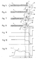
- FIG. 5 shows the situation in which the sawing tool 13 begins to penetrate into the workpiece 4 at point A.
- Fig. 6 the cut is continued so far that the sawing tool 13 begins to cut the workpiece at its full thickness h (point B).
- Fig. 7 is the cutting channel 5 so far advanced that the rising teeth on the back of the saw blade or sawing tool 13 begin with the so-called regrooving, if the opening width 2 of the cutting channel 5 has been reduced accordingly.
- Undercutting is understood to mean the process when the rising saw teeth 46 of the sawing tool 13 on the rear end of the sawing tool 13, seen in the feed direction 31, begin to cut into the workpiece and thus widen the narrowed cut channel 5 again.
- Fig. 8 detect the rising teeth of the sawing tool 13, the workpiece over its entire thickness h. From this point d, a regrooving over the entire thickness h of the workpiece 4 is thus possible if the opening width 2 along the cutting channel 5 has decreased accordingly.
- Fig. 9 to 11 are now different gradients recorded by the drive of the sawing tool 13 achievements P as a function of the position x of the axis of rotation of the sawing tool 13 along the cutting line 16 recorded.
- the vertical lines facilitate the local assignment.
- P represents the power consumed by the drive, which is not explicitly shown here but which allows the sawing tool 13 to rotate. This power can be measured by means known from the prior art.
- the drive power P is constant here at a low level. It is the area a. On the way from the situation gem. Fig. 5 to the situation gem. Fig. 6 increases the drive power P in the area b.
- the drive power in the area c remains constant.
- the distance d along the section line 16 is the area where the above-described regrooving can start. If it comes to regrooving, so here, as in the 10 and 11 to see the recorded by the drive of the sawing tool 13 drive power P again. Following in the area e, the entire sawing tool 13 is in the workpiece 4. Depending on the opening width 2 of the cutting channel 5, it comes to re-cutting or not.
- FIG. 10 shows an example in which the opening width 2 of the cutting channel 5 narrows so far that it comes to a trimming.
- Fig. 10 In this case, a situation is shown in which there is a constant narrowing of the cutting channel 5, so that the drive power P in the region e remains constant at an elevated level. The increase in the drive power P is the greater, the stronger the recutting.
- the in Fig. 10 illustrated case is rather rare. As a rule, material stresses tend to cause swaying constrictions of the cutting channel 5 over the path x. Examples of this are in Fig. 11 shown.
- a functional critical condition for the operation of the sawing device 3 is achieved in particular when the cutting channel in the area in which the master blade 45 is located, so strongly narrows that the master blade 45 of the sawing tool 13 is clamped.
- this leads to a very strong increase in the required drive power P of the sawing tool 13 and, depending on the power reserve of the sawing device 3, to stoppage or clamping of the sawing tool 13 in the cutting channel 5.
- the sawing tool 13 is frequently damaged or destroyed and the sawing device 3 itself is subjected to extreme stress exposed.
- Fig. 11 Such a situation is shown in dashed lines and denoted by the letter F.
- the approach of such situations should be recognized in good time in order to prevent jamming of the sawing tool 13 in time.
- Practice shows that this alone is not possible by monitoring the drive power P, since from a corresponding monitoring alone of the drive power P a correspondingly critical state often can be detected only too late. If the critical state is detected too late, then the sawing tool 13 can no longer be controlled out of the cutting channel 5 in order to avoid damage or a standstill.
- the device 1 according to the invention provides the possibility of detecting a possible jamming on the master blade 45 of the sawing tool 13 in good time in order to be able to initiate corresponding countermeasures in good time, thereby substantially increasing the reliability of the sawing device 3.
- the measuring fork or device 1 as in Fig.
- the corresponding reference value of the distance 11 is taken. Then, by means of the device 1 in the manner described, the opening width 2 of the cutting channel 5 are monitored from the beginning of the cutting or sawing process. At the same time, the drive power P of the sawing tool 13 can be monitored.
- the monitored drive power P can not provide timely indications of a critical narrowing of the opening width 2 of the cutting channel 5. If the opening width 2 is narrowed in this section of the sawing process so that the side walls of the workpiece 4 or 5 Thomaskanals meet the master blade 45 of the sawing tool 13, this acts as a disc brake, which at corresponding forces for immediate braking or standstill of the Sawing tool 13 can lead. This can lead to the destruction or considerable damage to the sawing tool 13 and / or sawing device 3. Particularly in this area, the already described monitoring by means of the device 1 according to the invention can warn in good time of a critical narrowing of the opening width 2 in order to avoid this situation.
- the criteria for defining the Pmax for power increase may be the same as for setting the threshold for opening 2 (eg material to be cut, type of sawing tool, machine power reserve, cutting speed and feed).
- the power threshold value Pmax has been determined as a function of the measured values of the device 1, jamming of the saw blade can now be effectively prevented during the further sawing process, without having to continue relying on the device 1 or measuring fork.
- An example of this is in Fig. 11 represented in the area e.
- the permissible threshold value Pmax is shown there.
- the drive power P exceeds this value, whereupon the sawing device 3 initiates appropriate countermeasures, which z. B. may be a reduction of the feed or a retraction or lowering of the sawing tool 13.
- the area indicated by the letter G shows a typical course of the drive powers P when the sawing tool is lowered. Clamping of the sawing tool 13 is successfully prevented here.
Landscapes
- Engineering & Computer Science (AREA)
- Mechanical Engineering (AREA)
- Sawing (AREA)
Claims (10)
- Dispositif (1) pour la surveillance de la largeur d'ouverture (2) d'un canal de coupe (5) à scier dans au moins une pièce (4) au moyen d'un outil de sciage (13) d'un dispositif de sciage (3), dans lequel le dispositif (1) comporte au moins un premier bras (6) à appliquer sur la pièce (4) sur un premier côté (7) du canal de coupe (5) et au moins un deuxième bras (8) à appliquer sur la pièce (4) sur un deuxième côté (9) du canal de coupe (5) opposé au premier côté (7), caractérisé en ce que le dispositif (1) présente un dispositif de mesure (10) pour la surveillance d'une distance (11) entre le premier bras (6) et le deuxième bras (8).
- Dispositif (1) selon la revendication 1, caractérisé en ce que le dispositif de mesure (10) pour la mesure, de préférence sans contact, de la distance (11), est de préférence un détecteur inductif.
- Dispositif (1) selon la revendication 1 ou 2, caractérisé en ce que le dispositif de mesure (10) est un dispositif de mesure pour la détermination de changements de la distance (11) par rapport à une distance de référence mesurable ou mesurée, de préférence au commencement de la surveillance.
- Dispositif (1) selon l'une quelconque des revendications 1 à 3, caractérisé en ce qu'une fente (12) pour le guidage d'un outil de sciage (13), de préférence d'une lame de scie, est disposée au moins localement entre les bras (6, 8).
- Dispositif (1) selon l'une quelconque des revendications 1 à 4, caractérisé en ce que les bras (6, 8) sont assemblés l'un à l'autre au moyen d'au moins un élément d'assemblage élastique (14), formant de préférence au moins une articulation pivotante, et/ou en ce qu'au moins un des bras (6, 8) est de configuration élastiquement flexible.
- Dispositif (1) selon la revendication 5, caractérisé en ce que l'élément d'assemblage (14) permet un pivotement et/ou un glissement relatif des bras (6, 8) l'un par rapport à l'autre contre une force de rappel élastique.
- Dispositif (1) selon l'une quelconque des revendications 1 à 6, caractérisé en ce que le dispositif (1) présente au moins une position de fonctionnement sans charge, dans laquelle une extrémité d'un des bras (6, 8), pour être appliquée sur la pièce (4), est saillante par rapport à une extrémité de l'autre des bras (6, 8) prévue pour être appliquée sur la pièce (4).
- Dispositif (1) selon l'une quelconque des revendications 1 à 7, caractérisé en ce qu'une pointe (15) ou une face de contact par friction est disposée sur au moins un, de préférence sur la totalité des bras (6, 8), à son/leur extrémité prévue pour être appliquée sur la pièce (4).
- Dispositif de sciage (3), en particulier installation de découpage de panneaux, comportant un dispositif (1) selon l'une quelconque des revendications 1 à 8.
- Dispositif de sciage (3) selon la revendication 9, caractérisé en ce que le dispositif (1) est relevable et abaissable, de préférence de façon motorisée, et/ou déplaçable, de préférence de façon motorisée, le long d'une ligne de coupe du dispositif de sciage (3), et/ou le dispositif (1) peut être disposé au moins dans la région d'une entrée de l'outil de sciage (13), en particulier d'une lame de scie, du dispositif de sciage (3) dans la pièce (4).
Applications Claiming Priority (1)
| Application Number | Priority Date | Filing Date | Title |
|---|---|---|---|
| AT11382010A AT510128B1 (de) | 2010-07-06 | 2010-07-06 | Einrichtung zur überwachung einer öffnungsweite |
Publications (2)
| Publication Number | Publication Date |
|---|---|
| EP2404694A1 EP2404694A1 (fr) | 2012-01-11 |
| EP2404694B1 true EP2404694B1 (fr) | 2012-11-14 |
Family
ID=44675388
Family Applications (1)
| Application Number | Title | Priority Date | Filing Date |
|---|---|---|---|
| EP20110004812 Active EP2404694B1 (fr) | 2010-07-06 | 2011-06-11 | Dispositif destiné à la surveillance d' une largeur d'ouverture |
Country Status (2)
| Country | Link |
|---|---|
| EP (1) | EP2404694B1 (fr) |
| AT (1) | AT510128B1 (fr) |
Families Citing this family (1)
| Publication number | Priority date | Publication date | Assignee | Title |
|---|---|---|---|---|
| CN113618470A (zh) * | 2021-08-17 | 2021-11-09 | 安徽鑫泰亿达装饰建材有限公司 | 一种铝型材数控双头精密切割锯床定位机构及其定位方法 |
Family Cites Families (6)
| Publication number | Priority date | Publication date | Assignee | Title |
|---|---|---|---|---|
| DE2641255C3 (de) | 1976-09-14 | 1980-10-23 | Gustav Wagner Maschinenfabrik, 7410 Reutlingen | Werkstückspannvorrichtung für eine Metall(kreis)-Sägemaschine |
| DE3238809A1 (de) * | 1982-10-20 | 1984-04-26 | Achenbach Buschhütten GmbH, 5910 Kreuztal | Werkstueckspannvorrichtung fuer metallsaegemaschinen |
| AT404810B (de) * | 1997-08-26 | 1999-03-25 | Schelling Anlagenbau Gmbh | Unterflursägemaschine |
| US6405624B2 (en) * | 1998-07-08 | 2002-06-18 | Delta International Machinery Corp. | Splitter and cutting member guard assembly |
| DE10026408A1 (de) * | 2000-05-18 | 2002-05-02 | Erwin Dimter | Materialfühler für Bearbeitungsaggregate dargestellt bei Metallkreissägen |
| DE10345993B4 (de) * | 2003-10-02 | 2008-07-24 | Fraunhofer-Gesellschaft zur Förderung der angewandten Forschung e.V. | Verfahren und Vorrichtung zum Messen und zum Feinstellen eines Werkzeuges in einem Werkzeughalter und Verfahren zum Messen einer Bearbeitungskraft |
-
2010
- 2010-07-06 AT AT11382010A patent/AT510128B1/de not_active IP Right Cessation
-
2011
- 2011-06-11 EP EP20110004812 patent/EP2404694B1/fr active Active
Also Published As
| Publication number | Publication date |
|---|---|
| AT510128A1 (de) | 2012-01-15 |
| AT510128B1 (de) | 2013-05-15 |
| EP2404694A1 (fr) | 2012-01-11 |
Similar Documents
| Publication | Publication Date | Title |
|---|---|---|
| EP3581310B1 (fr) | Machine à scier pour coupes d'onglet | |
| DE102007013455B4 (de) | Vorrichtung zum Schneiden von Bändern, Blechen oder dergleichen und Verfahren zur Bestimmung und/oder Kalibrierung des Schneidspaltes bei einer solchen Vorrichtung | |
| EP1993769B1 (fr) | Dispositif de sciage | |
| EP1834721B1 (fr) | Procédé et dispositif destinés à la commande en profondeur de rayures pour scies circulaires | |
| EP3022012B1 (fr) | Dispositif de serrage d'une pièce, machine-outil et procédé pour le serrage d'une pièce | |
| DE102008010383A1 (de) | Stanzwerkzeug, insbesondere zur Ablängung und Endenbearbeitung von Flachstabmaterial für Fensterbeschläge | |
| EP2708341B1 (fr) | Dispositif de découpe de carreaux | |
| EP2594355A1 (fr) | Machine de coupage et de soudage avec un dispositif de positionnement de deux extrémités de matériaux l'une contre l'autre | |
| EP3237136B1 (fr) | Dispositif et procédé de réglage de l'écart entre lames pour des cisailles à tambours destinées à la séparation transversale d'un ruban métallique | |
| DE7926084U1 (de) | Saegebandfuehrung fuer bandsaegemaschinen | |
| EP2404694B1 (fr) | Dispositif destiné à la surveillance d' une largeur d'ouverture | |
| DE202007002727U1 (de) | Stanzwerkzeug, insbesondere zur Ablängung und Endenbearbeitung von Flachstabmaterial für Fensterbeschläge | |
| DE69632953T2 (de) | Verfahren und vorrichtung zum halten von flitchen für schneidvorgänge | |
| EP3838527A1 (fr) | Dispositif de protection et procédé de protection | |
| EP2942136A2 (fr) | Dispositif et procédé de découpe en tranches d'un produit alimentaire congelé, en forme de tronçon | |
| DE19753563B4 (de) | Schneidvorrichtung für Flachmaterialbahnen | |
| DE29918249U1 (de) | Bandsägemaschine mit einem zum Führen des Bandrückens dienenden Führungselement | |
| EP1521647A1 (fr) | Presse a filage et procede correspondant | |
| EP2143516B1 (fr) | Ensemble de sciage pour une scie à panneaux verticale | |
| DE102008050475A1 (de) | Parallelanschlag | |
| DE102013207986B3 (de) | Plattenaufteilanlage | |
| EP2106889A2 (fr) | Règle de butée mobile | |
| EP3685984B1 (fr) | Procédé et dispositif de séparation de sections de profilé | |
| DE10144830B4 (de) | Trennverfahren zum Durchtrennen eines Metallträgers und Bandsägemaschine | |
| DE102006004464B4 (de) | Messerhalterung zur Befestigung eines Hackmessers an einer Messertrommel |
Legal Events
| Date | Code | Title | Description |
|---|---|---|---|
| AK | Designated contracting states |
Kind code of ref document: A1 Designated state(s): AL AT BE BG CH CY CZ DE DK EE ES FI FR GB GR HR HU IE IS IT LI LT LU LV MC MK MT NL NO PL PT RO RS SE SI SK SM TR |
|
| AX | Request for extension of the european patent |
Extension state: BA ME |
|
| PUAI | Public reference made under article 153(3) epc to a published international application that has entered the european phase |
Free format text: ORIGINAL CODE: 0009012 |
|
| 17P | Request for examination filed |
Effective date: 20120328 |
|
| GRAP | Despatch of communication of intention to grant a patent |
Free format text: ORIGINAL CODE: EPIDOSNIGR1 |
|
| GRAS | Grant fee paid |
Free format text: ORIGINAL CODE: EPIDOSNIGR3 |
|
| GRAP | Despatch of communication of intention to grant a patent |
Free format text: ORIGINAL CODE: EPIDOSNIGR1 |
|
| GRAA | (expected) grant |
Free format text: ORIGINAL CODE: 0009210 |
|
| AK | Designated contracting states |
Kind code of ref document: B1 Designated state(s): AL AT BE BG CH CY CZ DE DK EE ES FI FR GB GR HR HU IE IS IT LI LT LU LV MC MK MT NL NO PL PT RO RS SE SI SK SM TR |
|
| REG | Reference to a national code |
Ref country code: GB Ref legal event code: FG4D Free format text: NOT ENGLISH |
|
| REG | Reference to a national code |
Ref country code: AT Ref legal event code: REF Ref document number: 583679 Country of ref document: AT Kind code of ref document: T Effective date: 20121115 Ref country code: CH Ref legal event code: EP |
|
| REG | Reference to a national code |
Ref country code: CH Ref legal event code: NV Representative=s name: LUCHS AND PARTNER AG PATENTANWAELTE, CH |
|
| REG | Reference to a national code |
Ref country code: IE Ref legal event code: FG4D Free format text: LANGUAGE OF EP DOCUMENT: GERMAN |
|
| REG | Reference to a national code |
Ref country code: DE Ref legal event code: R096 Ref document number: 502011000194 Country of ref document: DE Effective date: 20130110 |
|
| REG | Reference to a national code |
Ref country code: NL Ref legal event code: VDEP Effective date: 20121114 |
|
| REG | Reference to a national code |
Ref country code: LT Ref legal event code: MG4D |
|
| PG25 | Lapsed in a contracting state [announced via postgrant information from national office to epo] |
Ref country code: HR Free format text: LAPSE BECAUSE OF FAILURE TO SUBMIT A TRANSLATION OF THE DESCRIPTION OR TO PAY THE FEE WITHIN THE PRESCRIBED TIME-LIMIT Effective date: 20121114 Ref country code: LT Free format text: LAPSE BECAUSE OF FAILURE TO SUBMIT A TRANSLATION OF THE DESCRIPTION OR TO PAY THE FEE WITHIN THE PRESCRIBED TIME-LIMIT Effective date: 20121114 Ref country code: FI Free format text: LAPSE BECAUSE OF FAILURE TO SUBMIT A TRANSLATION OF THE DESCRIPTION OR TO PAY THE FEE WITHIN THE PRESCRIBED TIME-LIMIT Effective date: 20121114 Ref country code: ES Free format text: LAPSE BECAUSE OF FAILURE TO SUBMIT A TRANSLATION OF THE DESCRIPTION OR TO PAY THE FEE WITHIN THE PRESCRIBED TIME-LIMIT Effective date: 20130225 Ref country code: NO Free format text: LAPSE BECAUSE OF FAILURE TO SUBMIT A TRANSLATION OF THE DESCRIPTION OR TO PAY THE FEE WITHIN THE PRESCRIBED TIME-LIMIT Effective date: 20130214 Ref country code: SE Free format text: LAPSE BECAUSE OF FAILURE TO SUBMIT A TRANSLATION OF THE DESCRIPTION OR TO PAY THE FEE WITHIN THE PRESCRIBED TIME-LIMIT Effective date: 20121114 |
|
| PG25 | Lapsed in a contracting state [announced via postgrant information from national office to epo] |
Ref country code: LV Free format text: LAPSE BECAUSE OF FAILURE TO SUBMIT A TRANSLATION OF THE DESCRIPTION OR TO PAY THE FEE WITHIN THE PRESCRIBED TIME-LIMIT Effective date: 20121114 Ref country code: GR Free format text: LAPSE BECAUSE OF FAILURE TO SUBMIT A TRANSLATION OF THE DESCRIPTION OR TO PAY THE FEE WITHIN THE PRESCRIBED TIME-LIMIT Effective date: 20130215 Ref country code: PT Free format text: LAPSE BECAUSE OF FAILURE TO SUBMIT A TRANSLATION OF THE DESCRIPTION OR TO PAY THE FEE WITHIN THE PRESCRIBED TIME-LIMIT Effective date: 20130314 Ref country code: SI Free format text: LAPSE BECAUSE OF FAILURE TO SUBMIT A TRANSLATION OF THE DESCRIPTION OR TO PAY THE FEE WITHIN THE PRESCRIBED TIME-LIMIT Effective date: 20121114 Ref country code: PL Free format text: LAPSE BECAUSE OF FAILURE TO SUBMIT A TRANSLATION OF THE DESCRIPTION OR TO PAY THE FEE WITHIN THE PRESCRIBED TIME-LIMIT Effective date: 20121114 |
|
| PG25 | Lapsed in a contracting state [announced via postgrant information from national office to epo] |
Ref country code: DK Free format text: LAPSE BECAUSE OF FAILURE TO SUBMIT A TRANSLATION OF THE DESCRIPTION OR TO PAY THE FEE WITHIN THE PRESCRIBED TIME-LIMIT Effective date: 20121114 Ref country code: SK Free format text: LAPSE BECAUSE OF FAILURE TO SUBMIT A TRANSLATION OF THE DESCRIPTION OR TO PAY THE FEE WITHIN THE PRESCRIBED TIME-LIMIT Effective date: 20121114 Ref country code: CZ Free format text: LAPSE BECAUSE OF FAILURE TO SUBMIT A TRANSLATION OF THE DESCRIPTION OR TO PAY THE FEE WITHIN THE PRESCRIBED TIME-LIMIT Effective date: 20121114 Ref country code: BG Free format text: LAPSE BECAUSE OF FAILURE TO SUBMIT A TRANSLATION OF THE DESCRIPTION OR TO PAY THE FEE WITHIN THE PRESCRIBED TIME-LIMIT Effective date: 20130214 Ref country code: RS Free format text: LAPSE BECAUSE OF FAILURE TO SUBMIT A TRANSLATION OF THE DESCRIPTION OR TO PAY THE FEE WITHIN THE PRESCRIBED TIME-LIMIT Effective date: 20121114 Ref country code: EE Free format text: LAPSE BECAUSE OF FAILURE TO SUBMIT A TRANSLATION OF THE DESCRIPTION OR TO PAY THE FEE WITHIN THE PRESCRIBED TIME-LIMIT Effective date: 20121114 |
|
| PG25 | Lapsed in a contracting state [announced via postgrant information from national office to epo] |
Ref country code: NL Free format text: LAPSE BECAUSE OF FAILURE TO SUBMIT A TRANSLATION OF THE DESCRIPTION OR TO PAY THE FEE WITHIN THE PRESCRIBED TIME-LIMIT Effective date: 20121114 Ref country code: RO Free format text: LAPSE BECAUSE OF FAILURE TO SUBMIT A TRANSLATION OF THE DESCRIPTION OR TO PAY THE FEE WITHIN THE PRESCRIBED TIME-LIMIT Effective date: 20121114 |
|
| PLBE | No opposition filed within time limit |
Free format text: ORIGINAL CODE: 0009261 |
|
| STAA | Information on the status of an ep patent application or granted ep patent |
Free format text: STATUS: NO OPPOSITION FILED WITHIN TIME LIMIT |
|
| 26N | No opposition filed |
Effective date: 20130815 |
|
| PG25 | Lapsed in a contracting state [announced via postgrant information from national office to epo] |
Ref country code: CY Free format text: LAPSE BECAUSE OF FAILURE TO SUBMIT A TRANSLATION OF THE DESCRIPTION OR TO PAY THE FEE WITHIN THE PRESCRIBED TIME-LIMIT Effective date: 20121114 |
|
| REG | Reference to a national code |
Ref country code: DE Ref legal event code: R097 Ref document number: 502011000194 Country of ref document: DE Effective date: 20130815 |
|
| BERE | Be: lapsed |
Owner name: SCHELLING ANLAGENBAU GMBH Effective date: 20130630 |
|
| PG25 | Lapsed in a contracting state [announced via postgrant information from national office to epo] |
Ref country code: MC Free format text: LAPSE BECAUSE OF FAILURE TO SUBMIT A TRANSLATION OF THE DESCRIPTION OR TO PAY THE FEE WITHIN THE PRESCRIBED TIME-LIMIT Effective date: 20121114 |
|
| REG | Reference to a national code |
Ref country code: IE Ref legal event code: MM4A |
|
| REG | Reference to a national code |
Ref country code: FR Ref legal event code: ST Effective date: 20140228 |
|
| PG25 | Lapsed in a contracting state [announced via postgrant information from national office to epo] |
Ref country code: BE Free format text: LAPSE BECAUSE OF NON-PAYMENT OF DUE FEES Effective date: 20130630 |
|
| PG25 | Lapsed in a contracting state [announced via postgrant information from national office to epo] |
Ref country code: IE Free format text: LAPSE BECAUSE OF NON-PAYMENT OF DUE FEES Effective date: 20130611 |
|
| PG25 | Lapsed in a contracting state [announced via postgrant information from national office to epo] |
Ref country code: FR Free format text: LAPSE BECAUSE OF NON-PAYMENT OF DUE FEES Effective date: 20130701 |
|
| PG25 | Lapsed in a contracting state [announced via postgrant information from national office to epo] |
Ref country code: MT Free format text: LAPSE BECAUSE OF FAILURE TO SUBMIT A TRANSLATION OF THE DESCRIPTION OR TO PAY THE FEE WITHIN THE PRESCRIBED TIME-LIMIT Effective date: 20121114 |
|
| PG25 | Lapsed in a contracting state [announced via postgrant information from national office to epo] |
Ref country code: SM Free format text: LAPSE BECAUSE OF FAILURE TO SUBMIT A TRANSLATION OF THE DESCRIPTION OR TO PAY THE FEE WITHIN THE PRESCRIBED TIME-LIMIT Effective date: 20121114 |
|
| PG25 | Lapsed in a contracting state [announced via postgrant information from national office to epo] |
Ref country code: TR Free format text: LAPSE BECAUSE OF FAILURE TO SUBMIT A TRANSLATION OF THE DESCRIPTION OR TO PAY THE FEE WITHIN THE PRESCRIBED TIME-LIMIT Effective date: 20121114 |
|
| PG25 | Lapsed in a contracting state [announced via postgrant information from national office to epo] |
Ref country code: LU Free format text: LAPSE BECAUSE OF NON-PAYMENT OF DUE FEES Effective date: 20130611 Ref country code: HU Free format text: LAPSE BECAUSE OF FAILURE TO SUBMIT A TRANSLATION OF THE DESCRIPTION OR TO PAY THE FEE WITHIN THE PRESCRIBED TIME-LIMIT; INVALID AB INITIO Effective date: 20110611 Ref country code: MK Free format text: LAPSE BECAUSE OF FAILURE TO SUBMIT A TRANSLATION OF THE DESCRIPTION OR TO PAY THE FEE WITHIN THE PRESCRIBED TIME-LIMIT Effective date: 20121114 |
|
| PGFP | Annual fee paid to national office [announced via postgrant information from national office to epo] |
Ref country code: GB Payment date: 20150630 Year of fee payment: 5 Ref country code: CH Payment date: 20150527 Year of fee payment: 5 |
|
| PG25 | Lapsed in a contracting state [announced via postgrant information from national office to epo] |
Ref country code: IS Free format text: LAPSE BECAUSE OF FAILURE TO SUBMIT A TRANSLATION OF THE DESCRIPTION OR TO PAY THE FEE WITHIN THE PRESCRIBED TIME-LIMIT Effective date: 20121114 |
|
| REG | Reference to a national code |
Ref country code: CH Ref legal event code: PL |
|
| GBPC | Gb: european patent ceased through non-payment of renewal fee |
Effective date: 20160611 |
|
| PG25 | Lapsed in a contracting state [announced via postgrant information from national office to epo] |
Ref country code: CH Free format text: LAPSE BECAUSE OF NON-PAYMENT OF DUE FEES Effective date: 20160630 Ref country code: LI Free format text: LAPSE BECAUSE OF NON-PAYMENT OF DUE FEES Effective date: 20160630 |
|
| PG25 | Lapsed in a contracting state [announced via postgrant information from national office to epo] |
Ref country code: GB Free format text: LAPSE BECAUSE OF NON-PAYMENT OF DUE FEES Effective date: 20160611 |
|
| PG25 | Lapsed in a contracting state [announced via postgrant information from national office to epo] |
Ref country code: AL Free format text: LAPSE BECAUSE OF FAILURE TO SUBMIT A TRANSLATION OF THE DESCRIPTION OR TO PAY THE FEE WITHIN THE PRESCRIBED TIME-LIMIT Effective date: 20121114 |
|
| REG | Reference to a national code |
Ref country code: DE Ref legal event code: R082 Ref document number: 502011000194 Country of ref document: DE Representative=s name: THIELKING & ELBERTZHAGEN PATENTANWAELTE, DE Ref country code: DE Ref legal event code: R081 Ref document number: 502011000194 Country of ref document: DE Owner name: IMA SCHELLING AUSTRIA GMBH, AT Free format text: FORMER OWNER: SCHELLING ANLAGENBAU GMBH, SCHWARZACH, AT |
|
| REG | Reference to a national code |
Ref country code: AT Ref legal event code: HC Ref document number: 583679 Country of ref document: AT Kind code of ref document: T Owner name: IMA SCHELLING AUSTRIA GMBH, AT Effective date: 20200121 |
|
| PGFP | Annual fee paid to national office [announced via postgrant information from national office to epo] |
Ref country code: DE Payment date: 20250626 Year of fee payment: 15 |
|
| PGFP | Annual fee paid to national office [announced via postgrant information from national office to epo] |
Ref country code: AT Payment date: 20250612 Year of fee payment: 15 |
|
| PGFP | Annual fee paid to national office [announced via postgrant information from national office to epo] |
Ref country code: IT Payment date: 20250623 Year of fee payment: 15 |