EP2404696A2 - Procédé de soudage par arc fusion forgeage avec régulation de l'énergie d'arc - Google Patents
Procédé de soudage par arc fusion forgeage avec régulation de l'énergie d'arc Download PDFInfo
- Publication number
- EP2404696A2 EP2404696A2 EP11401540A EP11401540A EP2404696A2 EP 2404696 A2 EP2404696 A2 EP 2404696A2 EP 11401540 A EP11401540 A EP 11401540A EP 11401540 A EP11401540 A EP 11401540A EP 2404696 A2 EP2404696 A2 EP 2404696A2
- Authority
- EP
- European Patent Office
- Prior art keywords
- arc
- work piece
- voltage
- welding process
- metal object
- Prior art date
- Legal status (The legal status is an assumption and is not a legal conclusion. Google has not performed a legal analysis and makes no representation as to the accuracy of the status listed.)
- Granted
Links
Images


Classifications
-
- B—PERFORMING OPERATIONS; TRANSPORTING
- B23—MACHINE TOOLS; METAL-WORKING NOT OTHERWISE PROVIDED FOR
- B23K—SOLDERING OR UNSOLDERING; WELDING; CLADDING OR PLATING BY SOLDERING OR WELDING; CUTTING BY APPLYING HEAT LOCALLY, e.g. FLAME CUTTING; WORKING BY LASER BEAM
- B23K9/00—Arc welding or cutting
- B23K9/20—Stud welding
- B23K9/201—Stud welding of the extremity of a small piece on a large basis
-
- B—PERFORMING OPERATIONS; TRANSPORTING
- B23—MACHINE TOOLS; METAL-WORKING NOT OTHERWISE PROVIDED FOR
- B23K—SOLDERING OR UNSOLDERING; WELDING; CLADDING OR PLATING BY SOLDERING OR WELDING; CUTTING BY APPLYING HEAT LOCALLY, e.g. FLAME CUTTING; WORKING BY LASER BEAM
- B23K9/00—Arc welding or cutting
- B23K9/20—Stud welding
Definitions
- the invention relates to a process for drawn arc welding of fasteners to a work piece.
- drawn arc fastener welding is performed using a constant current welding process with a fixed arc current and a fixed arc time as welding parameters that are maintained by a drawn arc stud welding power source.
- Other process variables include a lift height and plunge depth that are typically controlled by various mechanisms including mechanical mechanisms as well as electronically controlled devices.
- the lift height and weld puddle depression create an arc gap between the fastener and work piece, and the length of the arc gap and the ionization potential gradient of the arc plasma together with fixed anode and cathode drops establish an arc voltage.
- the product of the arc voltage and arc current is an arc power which may be multiplied by an arc time to compute an arc energy.
- the amount of arc energy serves as the heat source that melts both the fastener and the work piece.
- the resultant heat generated by the arc energy may have an effect on the process stability and weld quality performed in a welding operation.
- a drawn arc welding process that includes the steps of providing a work piece, providing a welding tool holding a metal object onto the work piece, providing a power supply outputting a pilot arc current, providing an arc voltage sensing device, lifting the metal object apart from the work piece and drawing an arc at pilot arc current, energizing a preset welding current locally melting the metal object and forming a weld pool in the work piece, measuring an arc voltage, accumulating arc energy, predicting the arc voltage for a remaining time of the welding process, regulating the time of the welding process wherein the accumulated arc energy and predicted arc voltage are utilized to achieve a desired total energy input set point, and plunging the fastener into the locally melted work piece forming a weld between the metal object and the work piece.
- a drawn arc welding process that includes the steps of providing a work piece, providing a welding tool holding a metal object onto the work piece, providing a power supply outputting a preset current, providing an arc voltage sensing device, lifting the metal object apart from the work piece and drawing an arc at pilot arc current, energizing a preset welding current locally melting the metal object and forming a weld pool in the work piece measuring an arc in multiple measurement phases including a first phase having an initial melting of a surface or surface coating of the work piece wherein the measured arc voltage is discarded and additional phases wherein the arc voltage is measured and stored, predicting the arc voltage for a remaining time of the welding process, accumulating arc energy, regulating the time of the welding process wherein the accumulated arc energy and predicted arc voltage are utilized to achieve a desired energy input set point, and plunging the fastener into the locally melted work piece forming a weld between the metal object and the work piece.
- a drawn arc welding process that includes the steps of providing a work piece, providing a welding tool holding a metal object onto the work piece, providing a power supply outputting a preset current, providing an arc voltage sensing device, lifting the metal object apart from the work piece and drawing an arc at pilot arc current, energizing a preset welding current locally melting the metal object and forming a weld pool in the work piece, measuring an arc in multiple measurement phases including a first phase having an initial melting of a surface or surface coating of the work piece wherein the measured arc voltage is discarded and additional phases wherein the arc voltage is measured and stored and wherein the measuring step includes measuring the voltage at output terminals of the welder and subtracting a cable and connector voltage drop estimated from a previous weld during stud plunge, predicting the arc voltage for a remaining time of the welding process, accumulating arc energy, regulating the time of the welding process wherein the accumulated arc energy and predicted arc voltage are utilized to achieve
- a drawn arc welding process that includes the steps of providing a work piece, providing a welding tool holding a metal object onto the work piece, providing a power supply, providing an arc voltage sensing device, lifting the metal object and drawing a pilot arc, measuring a voltage in the pilot arc, calculating a current set point or a time for a main arc based on the measured voltage in the pilot arc, energizing a main arc current locally melting the metal object and forming a weld pool in the work piece, plunging the metal object into the locally melted work piece forming a weld between the metal object and the work piece wherein a desired arc energy input is maintained.
- Figure 1 is a block diagram of a constant energy welding process feedback control logic
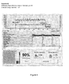
- Figure 2 is a graph of the arc voltage and arc current as a function of time for a reference weld
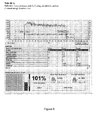
- Figure 3 is a graph of the arc current and arc voltage including an increased gun lift in comparison to the reference of figure 2 that does not utilize a constant energy input control;
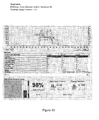
- Figure 4 is a graph of the arc current and arc voltage as a function of time including the increased gun lift of Figure 3 and including a constant energy input control;
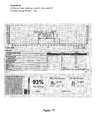
- Figure 5 is a graph of the arc current and arc voltage as a function of time including a decreased gun lift in comparison to the reference of figure 2 without a constant energy input control;
- Figure 6 is a graph of the arc current and arc voltage including a decreased gun lift of Figure 5 and including a constant energy input control;
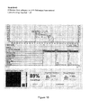
- Figure 7 is a graph of the arc current and arc voltage as a function of time that includes cutting oil added to a surface of a work piece in comparison to the reference of figure 2 with a constant energy input control not included;
- Figure 8 is a graph of the arc current and arc voltage as a function of time in comparison to the reference including cutting oil as in Figure 7 and including a constant energy input control;
- Figure 9 is a graph of an arc voltage and arc current as a function of time for a short cycle welding process and is a reference weld;
- Figure 10 is a graph of the arc voltage and arc current as a function of time differing from the reference of Figure 9 and including cutting oil added to a surface of a work piece with a constant energy input control not included;
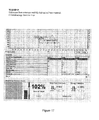
- Figure 11 is a graph of the arc current and arc voltage as a function of time differing from the reference of Figure 9 and including cutting oil added to a surface of the work piece with a constant energy input control;
- Figure 12 is a graph of the arc current and arc voltage as a function of time differing from the reference of Figure 9 and including an increased lift with a constant energy input control not included;
- Figure 13 is a graph of the arc current and arc voltage as a function of time differing from the reference of Figure 9 including an increased lift and including a constant energy input control;
- Figure 14 is a graph of the arc current and arc voltage as a function of time differing from the reference of Figure 9 and including a decreased lift with a constant energy input control not included;
- Figure 15 is a graph of the arc current and arc voltage as a function of time differing from the reference of Figure 9 including a decreased lift and including a constant energy input control;
- Figure 16 is a graph of the arc current and arc voltage as a function of time differing from the reference of Figure 9 and including a galvanized base material without a constant energy input control;
- Figure 17 is a graph of the arc current and arc voltage as a function of time differing from the reference of Figure 9 and including a galvanized base material with a constant energy input control;
- Figure 18 is a graphical depiction of a short cycle weld including studs attached to a mild steel base material
- Figure 19 is a graphical view of a short cycle weld including studs attached to a galvanized base material
- Figure 20 is a graphical depiction of a drawn arc weld after bend test including a mild steel base and cutting oil applied to the base material;
- Figure 21 is a graph of the arc voltage and arc current as a function of time for a reference weld according to an alternative embodiment having a regulated energy input;
- Figure 22 is a graph of the arc current and arc voltage as a function of time that includes cutting oil added to a surface of a work piece in comparison to figure 21 .
- a drawn arc welding process that includes the steps of providing a work piece, providing a welding tool holding a metal object onto the work piece, providing a power supply outputting a preset current, providing an arc voltage sensing device, lifting the metal object and drawing a pilot arc, energizing a welding current locally melting the metal object and forming a weld pool in the work piece, measuring an arc voltage at early stages of welding time, accumulating an arc energy, predicting the arc voltage for a remaining time of the welding process, regulating the time of later stages of the welding time wherein the accumulated arc energy and predicted arc voltage are utilized to achieve a desired energy input set point, and then plunging the metal object into the locally melted work piece forming a weld between the metal object and the work piece.
- the accumulating energy may include a pilot arc energy and an energy applied in a cleaning step of the pilot arc, as well as the main arc welding current.
- metal objects may be attached to a work piece.
- Metal objects may include a fastener, a metal stud, a metal nut, a metal shaft, and a metal bracket. It should be realized that various metal objects may include different shapes and configurations that may be welded to a work piece.
- the step of measuring an arc voltage may include multiple measurement phases.
- a first phase may include an initial melting of a surface of the work piece wherein the measured arc voltage is not utilized in the predicting step because the voltage is not stable.
- the step of measuring an arc voltage may include additional phases wherein the arc voltage is measured and stored for use in the predicting step.
- the step of measuring an arc voltage may include measuring the voltage at output terminals of the welder and subtracting a cable and connector voltage drop that is estimated from a previous weld during stud plunge or from a cable drop measurement or calibration procedure.
- the cable and connector voltage drop may be estimated following a plunge of the previous weld wherein a short circuit is created between the stud the weld pool and the current is maintained and a resistance is calculated from a measured voltage and measured current. The resistance may be multiplied by the current of the welding process to estimate the cable and connector voltage drop.
- the step of predicting an arc voltage for a remaining time of the welding process may include calculating an average arc voltage of the additional measurement phases and then linearly extrapolating the data to determine a predicted future arc voltage.
- the measured and stored arc voltages of the additional phases may be subjected to a second order or higher order polynomial regression to determine the predicted future arc voltage.
- the step of calculating the time of the remaining welding process includes utilizing a varying arc energy having a main arc current and a different plunge arc current.
- a desired energy input is applied as a set point for the welding process.
- the desired energy input may be determined based on varying characteristics of the welding process as well as the materials utilized in the welding process. For example, the desired energy input may be determined in relation to the metal object being welded, the position of the welding operation, conditions of the welding operation, as well as the type and thickness of work piece being utilized and the work piece back-side heat mark requirement.
- process parameters including welding operations having differences in lift and plunge heights as well as the conditions of both the work piece and metal objects will be discussed in more detail below.
- the drawn arc welding process may include a duration greater than 100 milliseconds and may include a ferrule positioned about the metal object. Additionally, the process may be a short cycle process less than 100 milliseconds wherein a gas shielding may or may not be used to protect oxidation of a weld zone.
- Power supplies may include an inverter controlled by a microprocessor having either pulse width modulation or phase shift control, a silicon controlled rectifier current regulated power source, and a buck converter based power source fed by a direct current voltage source.
- the total welding arc time may be divided into sequential phases or time segments.
- the first phase is a settling phase wherein a surface coating is burnt off of a work piece and the arc voltage may become unstable or change dramatically.
- the arc voltage is monitored but the reading is not stored for use during the predicting step.
- the arc voltage is recorded and analyzed for the purpose of forecasting for a remaining time of the welding process.
- various forecast or predicting methods may be utilized including linear extrapolation as well as higher order polynomial regressions.
- this phase may be subdivided into two time segments labeled as quadrant two and quadrant three.
- An average reading of the arc voltage of the first time segment and the second time segment may be utilized to extrapolate and predict a future voltage trend for the remaining time of the process.
- the last phase of Figure 1 includes an adjustment phase that is based on the forecast or predicted voltage trend in the predicting step. In the last phase a calculation is performed to determine the time needed such that a total energy of phase one and phase two which were measured and a forecasted energy of phase three will add up to a desired energy set point.
- V 2 and V 3 are mean voltage of quadrant 2 and 3
- E 1 , E 2 and E 3 are mean energy of quadrant 1, 2 and 3 respectively.
- E sp is the desired energy set point.
- the needed 4 th quadrant energy to satisfy E sp is
- E 4 E sp - E 0 - E 1 - E 2 - E 3
- E 1, E 2 and E 3 are actual energy of the first, second and third quadrant measured and accumulated
- E 0 is the accumulated pilot arc energy.
- the process of the present invention may be implemented utilizing an energy set point that is saved as a preset in a welding power supply.
- known power supplies may include a current set point and time set point.
- the use of an energy set point in conjunction with the outlined processes of the present invention allows additional control over a welding operation not present in prior art processes.
- the presets may be associated with a particular fastener in a particular welding position or condition. Additionally, when a preset is recalled by the welding controller, a programmed current, time (as a starting point before the adjustment), and energy set point will also be recalled together to achieve a constant energy input for a particular fastener welding application.
- the preset may include a current having a constant level or a pulsed waveform.
- the examples embodied in Figures 2-8 include the use of a Nelweld N1500i power supply.
- a Nelson NS-40 medium duty hand gun with a short cycle core and without a plunge dampener was utilized.
- Various studs and ferrules were utilized in the various examples with a drawn arc stud of 3/8 of an inch and included the use of a drawn arc ferrule.
- the short cycle examples detailed in Figures 9-17 include the use of a short cycle stud.
- a welding cable including a number 1 AWG 25-foot cable was utilized to link the welding gun to the power supply.
- the welding gun included a stud negative polarity.
- the experimental procedure included performing a weld that is then set as a target. Following, a reference weld is performed showing a consistency to the set point. Following the reference weld, various weld conditions were changed to demonstrate a change in voltage which would normally change the overall energy input in a welding operation. Then a constant energy function according to the process is enabled and adjustments are adaptively made to overcome the voltage changes and deliver a similar amount of energy as the target weld.
- Figures 2-8 detail experimental results of a welding process including a 3/8 inch stud in which various processing parameters are adjusted with both a constant energy input and without a constant energy input.
- the results detailed in Figures 2-8 are shown in Table 1 which details the arc current, arc voltage, arc time, energy, gun lift, and percent energy of the target.
- Figures 9-17 detail experimental results of a welding process including a 3/8 inch stud in which various processing parameters are adjusted with both a constant energy input and without a constant energy input.
- the results detailed in Figures 9-17 are shown in Table 1 which details the arc current, arc voltage, arc time, energy, gun lift, and percent energy of the target for a short cycle weld.
- the constant energy input as embodied in the process significantly reduces the difference in weld energy applied to the welding process when various conditions are changed. For example, when the lift of the gun is increased the difference in weld energy applied to the weld without the use of the process including the constant energy input realizes a difference of 14% in energy applied to the weld. This is in comparison to the difference of 2% of a difference in weld energy applied to the welding process when the constant energy input as embodied in the process is utilized. A resulting error of 12% is removed as a result of the process including the constant energy input. Various summaries of the percent removed as well as the corrected differences in energy applied to the welds are detailed in Table 2.
- an alternative embodiment of a drawn arc welding process may include the steps of providing a work piece, providing a welding tool holding a metal object onto the work piece, providing a power supply, providing an arc voltage sensing device, lifting the metal object and drawing a pilot arc, measuring a voltage in the pilot arc, calculating a current set point or a current time for a main arc based on the measured voltage in the pilot arc, energizing a main arc current locally melting the metal object and forming a weld pool in the work piece, plunging the metal object into the locally melted work piece forming a weld between the metal object and the work piece wherein a desired arc energy input is maintained.
- FIGs 21 and 22 there are shown graphs of the voltage 100, 200, current 101, 201 and stud or metal object position 102, 202 as a function of time for a work piece without oil in Figure 21 and with oil in Figure 22 .
- the pilot arc voltage is shown to vary from figures 21 and 22 due to the presence of the oil on the surface of the work piece.
- the voltage in the pilot arc is shown as being higher or increased due to the presence of the oil on the work piece in Figure 22 .
- the pilot arc current around 15A is engaged with a voltage around 15V.
- the voltage is about 19-20V.
- the arc voltage during the pilot arc stage is measured and the main arc current "set-point" is determined based on a mathematical formula or a look-up table, and regulated to the calculated main arc current set-point.
- the main current is reduced by about 130A to compensate for a higher arc voltage due to oil.
- the process including the step of measuring the voltage in the pilot arc may modify the current set point or time in the main arc to compensate for varying conditions, such that a desired arc energy input may be maintained.
- the step of calculating the current or time of the main arc may account for various work pieces, metal objects and other parameters such as the surface condition. In the depicted graph of Figure 22 , the calculation step results in a lower current set point for the current in comparison to that of figure 21 . In this manner a desired arc energy input can be maintained that can compensate for differences in the surface of a work piece or other variation.
- the main arc current may be maintained at a substantially constant level in the main arc as shown in Figures 21 and 22 .
Landscapes
- Engineering & Computer Science (AREA)
- Physics & Mathematics (AREA)
- Plasma & Fusion (AREA)
- Mechanical Engineering (AREA)
- Arc Welding Control (AREA)
- Arc Welding In General (AREA)
Applications Claiming Priority (1)
| Application Number | Priority Date | Filing Date | Title |
|---|---|---|---|
| US12/830,764 US8513569B2 (en) | 2010-07-06 | 2010-07-06 | Arc energy regulation in drawn arc fastener welding process |
Publications (3)
| Publication Number | Publication Date |
|---|---|
| EP2404696A2 true EP2404696A2 (fr) | 2012-01-11 |
| EP2404696A3 EP2404696A3 (fr) | 2012-03-28 |
| EP2404696B1 EP2404696B1 (fr) | 2017-06-14 |
Family
ID=44719804
Family Applications (1)
| Application Number | Title | Priority Date | Filing Date |
|---|---|---|---|
| EP11401540.7A Active EP2404696B1 (fr) | 2010-07-06 | 2011-07-06 | Procédé de soudage par arc fusion forgeage avec régulation de l'énergie d'arc |
Country Status (3)
| Country | Link |
|---|---|
| US (1) | US8513569B2 (fr) |
| EP (1) | EP2404696B1 (fr) |
| ES (1) | ES2654191T3 (fr) |
Cited By (1)
| Publication number | Priority date | Publication date | Assignee | Title |
|---|---|---|---|---|
| EP3492207A1 (fr) * | 2017-12-04 | 2019-06-05 | HILTI Aktiengesellschaft | Appareil et procédé de soudage de goujons |
Family Cites Families (15)
| Publication number | Priority date | Publication date | Assignee | Title |
|---|---|---|---|---|
| US3575573A (en) * | 1968-06-20 | 1971-04-20 | Lincoln Electric Co | Method of and power supply for electric arc welding |
| DE3130389A1 (de) | 1981-07-31 | 1983-02-17 | Tucker Gmbh, 6300 Giessen | Pruefverfahren fuer das anschweissen von bauteilen, insbesondere schweissbolzen, an werkstuecken mittels gezogenem lichtbogen |
| EP0117925B1 (fr) | 1983-03-05 | 1987-07-15 | Weld-Equip B.V. | Dispositif de soudage à l'arc commandé automatiquement pour souder des éléments de support à une pièce d'usinage |
| CZ231092A3 (en) * | 1991-08-02 | 1993-02-17 | Emhart Inc | Arc welded joint between a carrier and a detail attached fixedly thereto |
| CH688186A5 (de) | 1994-10-03 | 1997-06-13 | Ifa Internationale Finanzansta | Schweissverfahren zum Verbinden einer Komponente mit einem Werkstueck und Vorrichtung zum Ausfuehren des Verfahrens. |
| JP3369345B2 (ja) * | 1995-02-16 | 2003-01-20 | ポップリベット・ファスナー株式会社 | スタッド溶接機 |
| DE19509172C1 (de) | 1995-03-14 | 1996-08-29 | Trw Nelson Bolzenschweisstechn | Schweißverfahren für das Hubzündungsbolzenschweißen |
| DE19524490B4 (de) * | 1995-07-05 | 2005-06-09 | Newfrey Llc, Newark | Verfahren zum Verschweißen von Schweißbolzen mit einem Werkstück |
| US6660958B2 (en) | 2000-08-30 | 2003-12-09 | Newfrey Llc | Arc welding method and apparatus |
| US7176401B2 (en) | 2001-07-04 | 2007-02-13 | Newfrey Llc | Method and device for welding an aluminum-based stud |
| US6713708B2 (en) | 2002-03-01 | 2004-03-30 | Arcon Welding Llc | Portable drawn arc stud welding apparatus and method providing high current output in short time intervals |
| DE102007039306B4 (de) | 2007-08-10 | 2014-05-15 | Ltg Aktiengesellschaft | Luftauslass |
| DE102007039308A1 (de) * | 2007-08-10 | 2009-02-12 | Newfrey Llc, Newark | Verfahren zum Kurzzeit-Bolzen Fügen |
| JP5159955B2 (ja) | 2008-09-16 | 2013-03-13 | ドルビー ラボラトリーズ ライセンシング コーポレイション | 適応的ビデオ・エンコーダ制御 |
| EP2342038A4 (fr) * | 2008-09-16 | 2013-10-23 | Nelson Stud Welding Inc | Contrôle de forme d'onde lors du soudage par arc fusion forgeage |
-
2010
- 2010-07-06 US US12/830,764 patent/US8513569B2/en active Active
-
2011
- 2011-07-06 ES ES11401540.7T patent/ES2654191T3/es active Active
- 2011-07-06 EP EP11401540.7A patent/EP2404696B1/fr active Active
Non-Patent Citations (1)
| Title |
|---|
| None |
Cited By (4)
| Publication number | Priority date | Publication date | Assignee | Title |
|---|---|---|---|---|
| EP3492207A1 (fr) * | 2017-12-04 | 2019-06-05 | HILTI Aktiengesellschaft | Appareil et procédé de soudage de goujons |
| WO2019110241A1 (fr) * | 2017-12-04 | 2019-06-13 | Hilti Aktiengesellschaft | Dispositif et procédé de soudage de goujons |
| US11660694B2 (en) | 2017-12-04 | 2023-05-30 | Hilti Aktiengesellschaft | Stud welding device and stud welding method |
| TWI806910B (zh) * | 2017-12-04 | 2023-07-01 | 列支敦斯登商喜利得股份有限公司 | 焊接設備和方法 |
Also Published As
| Publication number | Publication date |
|---|---|
| EP2404696A3 (fr) | 2012-03-28 |
| EP2404696B1 (fr) | 2017-06-14 |
| US20120006801A1 (en) | 2012-01-12 |
| ES2654191T3 (es) | 2018-02-12 |
| US8513569B2 (en) | 2013-08-20 |
Similar Documents
| Publication | Publication Date | Title |
|---|---|---|
| JP5988015B1 (ja) | 抵抗スポット溶接方法 | |
| US12090583B2 (en) | Systems and methods for adaptive control of wire preheating | |
| US20120145691A1 (en) | Arc welding method and arc welding apparatus | |
| US7235760B2 (en) | AC pulse arc welding method | |
| US11648619B2 (en) | Method and device for making a workpiece surface of a metal workpiece | |
| JP6652228B1 (ja) | 抵抗スポット溶接方法および溶接部材の製造方法 | |
| CN104768695B (zh) | 基于代表性参数监测gmaw脉冲中接触末端的寿命的方法 | |
| Arya et al. | Parametric optimization of mig process parameters using Taguchi and grey Taguchi analysis | |
| EP3266553A1 (fr) | Procédé de soudage par points par résistance et joint soudé | |
| US20150375325A1 (en) | Adaptive welding apparatus, control system, and method of controlling an adaptive welding apparatus | |
| US9579744B2 (en) | Resistance welding with minimized weld expulsion | |
| WO2022209432A1 (fr) | Procédé de commande de soudage, alimentation électrique de soudage, système de soudage, procédé de soudage et procédé de fabrication additive | |
| EP2404696B1 (fr) | Procédé de soudage par arc fusion forgeage avec régulation de l'énergie d'arc | |
| US8710404B2 (en) | Method and apparatus to maintain welding current to compensate for deterioration of welding contact tip | |
| EP4023384B1 (fr) | Procédé de soudage par points par résistance et procédé de production d'un élément soudé | |
| KR102021893B1 (ko) | 자동 용접장치로 튜브시트 용접 시 제어알고리즘을 이용한 용착 제어 방법 | |
| EP4494800A1 (fr) | Procédé de soudage par points | |
| Ghogale et al. | Optimisation of process parameters of MIG welding to improve quality of weld by using Taguchi methodology | |
| JP3761498B2 (ja) | 亜鉛めっき鋼板のスポット溶接自動組付け方法 | |
| US12214438B2 (en) | Spatter detection method | |
| CA3070457C (fr) | Systemes et procede de commande adaptative de prechauffage de fil | |
| JP7534057B2 (ja) | 溶接部の通電状態監視方法及び抵抗溶接機の制御装置 | |
| JP3120933B2 (ja) | 抵抗溶接制御方法 | |
| JP3328378B2 (ja) | 高周波加熱装置 |
Legal Events
| Date | Code | Title | Description |
|---|---|---|---|
| AK | Designated contracting states |
Kind code of ref document: A2 Designated state(s): AL AT BE BG CH CY CZ DE DK EE ES FI FR GB GR HR HU IE IS IT LI LT LU LV MC MK MT NL NO PL PT RO RS SE SI SK SM TR |
|
| AX | Request for extension of the european patent |
Extension state: BA ME |
|
| PUAI | Public reference made under article 153(3) epc to a published international application that has entered the european phase |
Free format text: ORIGINAL CODE: 0009012 |
|
| PUAL | Search report despatched |
Free format text: ORIGINAL CODE: 0009013 |
|
| AK | Designated contracting states |
Kind code of ref document: A3 Designated state(s): AL AT BE BG CH CY CZ DE DK EE ES FI FR GB GR HR HU IE IS IT LI LT LU LV MC MK MT NL NO PL PT RO RS SE SI SK SM TR |
|
| AX | Request for extension of the european patent |
Extension state: BA ME |
|
| RIC1 | Information provided on ipc code assigned before grant |
Ipc: B23K 9/20 20060101AFI20120222BHEP |
|
| 17P | Request for examination filed |
Effective date: 20120927 |
|
| 17Q | First examination report despatched |
Effective date: 20130312 |
|
| GRAP | Despatch of communication of intention to grant a patent |
Free format text: ORIGINAL CODE: EPIDOSNIGR1 |
|
| INTG | Intention to grant announced |
Effective date: 20160718 |
|
| GRAJ | Information related to disapproval of communication of intention to grant by the applicant or resumption of examination proceedings by the epo deleted |
Free format text: ORIGINAL CODE: EPIDOSDIGR1 |
|
| INTC | Intention to grant announced (deleted) | ||
| GRAP | Despatch of communication of intention to grant a patent |
Free format text: ORIGINAL CODE: EPIDOSNIGR1 |
|
| INTG | Intention to grant announced |
Effective date: 20170104 |
|
| GRAS | Grant fee paid |
Free format text: ORIGINAL CODE: EPIDOSNIGR3 |
|
| GRAA | (expected) grant |
Free format text: ORIGINAL CODE: 0009210 |
|
| AK | Designated contracting states |
Kind code of ref document: B1 Designated state(s): AL AT BE BG CH CY CZ DE DK EE ES FI FR GB GR HR HU IE IS IT LI LT LU LV MC MK MT NL NO PL PT RO RS SE SI SK SM TR |
|
| REG | Reference to a national code |
Ref country code: GB Ref legal event code: FG4D |
|
| REG | Reference to a national code |
Ref country code: CH Ref legal event code: EP Ref country code: AT Ref legal event code: REF Ref document number: 900494 Country of ref document: AT Kind code of ref document: T Effective date: 20170615 |
|
| REG | Reference to a national code |
Ref country code: IE Ref legal event code: FG4D |
|
| REG | Reference to a national code |
Ref country code: DE Ref legal event code: R096 Ref document number: 602011038680 Country of ref document: DE |
|
| REG | Reference to a national code |
Ref country code: FR Ref legal event code: PLFP Year of fee payment: 7 |
|
| REG | Reference to a national code |
Ref country code: NL Ref legal event code: MP Effective date: 20170614 |
|
| REG | Reference to a national code |
Ref country code: LT Ref legal event code: MG4D |
|
| PG25 | Lapsed in a contracting state [announced via postgrant information from national office to epo] |
Ref country code: HR Free format text: LAPSE BECAUSE OF FAILURE TO SUBMIT A TRANSLATION OF THE DESCRIPTION OR TO PAY THE FEE WITHIN THE PRESCRIBED TIME-LIMIT Effective date: 20170614 Ref country code: LT Free format text: LAPSE BECAUSE OF FAILURE TO SUBMIT A TRANSLATION OF THE DESCRIPTION OR TO PAY THE FEE WITHIN THE PRESCRIBED TIME-LIMIT Effective date: 20170614 Ref country code: FI Free format text: LAPSE BECAUSE OF FAILURE TO SUBMIT A TRANSLATION OF THE DESCRIPTION OR TO PAY THE FEE WITHIN THE PRESCRIBED TIME-LIMIT Effective date: 20170614 Ref country code: GR Free format text: LAPSE BECAUSE OF FAILURE TO SUBMIT A TRANSLATION OF THE DESCRIPTION OR TO PAY THE FEE WITHIN THE PRESCRIBED TIME-LIMIT Effective date: 20170915 Ref country code: NO Free format text: LAPSE BECAUSE OF FAILURE TO SUBMIT A TRANSLATION OF THE DESCRIPTION OR TO PAY THE FEE WITHIN THE PRESCRIBED TIME-LIMIT Effective date: 20170914 |
|
| REG | Reference to a national code |
Ref country code: AT Ref legal event code: MK05 Ref document number: 900494 Country of ref document: AT Kind code of ref document: T Effective date: 20170614 |
|
| PG25 | Lapsed in a contracting state [announced via postgrant information from national office to epo] |
Ref country code: NL Free format text: LAPSE BECAUSE OF FAILURE TO SUBMIT A TRANSLATION OF THE DESCRIPTION OR TO PAY THE FEE WITHIN THE PRESCRIBED TIME-LIMIT Effective date: 20170614 Ref country code: BG Free format text: LAPSE BECAUSE OF FAILURE TO SUBMIT A TRANSLATION OF THE DESCRIPTION OR TO PAY THE FEE WITHIN THE PRESCRIBED TIME-LIMIT Effective date: 20170914 Ref country code: SE Free format text: LAPSE BECAUSE OF FAILURE TO SUBMIT A TRANSLATION OF THE DESCRIPTION OR TO PAY THE FEE WITHIN THE PRESCRIBED TIME-LIMIT Effective date: 20170614 Ref country code: LV Free format text: LAPSE BECAUSE OF FAILURE TO SUBMIT A TRANSLATION OF THE DESCRIPTION OR TO PAY THE FEE WITHIN THE PRESCRIBED TIME-LIMIT Effective date: 20170614 Ref country code: RS Free format text: LAPSE BECAUSE OF FAILURE TO SUBMIT A TRANSLATION OF THE DESCRIPTION OR TO PAY THE FEE WITHIN THE PRESCRIBED TIME-LIMIT Effective date: 20170614 |
|
| PG25 | Lapsed in a contracting state [announced via postgrant information from national office to epo] |
Ref country code: CZ Free format text: LAPSE BECAUSE OF FAILURE TO SUBMIT A TRANSLATION OF THE DESCRIPTION OR TO PAY THE FEE WITHIN THE PRESCRIBED TIME-LIMIT Effective date: 20170614 Ref country code: AT Free format text: LAPSE BECAUSE OF FAILURE TO SUBMIT A TRANSLATION OF THE DESCRIPTION OR TO PAY THE FEE WITHIN THE PRESCRIBED TIME-LIMIT Effective date: 20170614 Ref country code: EE Free format text: LAPSE BECAUSE OF FAILURE TO SUBMIT A TRANSLATION OF THE DESCRIPTION OR TO PAY THE FEE WITHIN THE PRESCRIBED TIME-LIMIT Effective date: 20170614 Ref country code: SK Free format text: LAPSE BECAUSE OF FAILURE TO SUBMIT A TRANSLATION OF THE DESCRIPTION OR TO PAY THE FEE WITHIN THE PRESCRIBED TIME-LIMIT Effective date: 20170614 Ref country code: RO Free format text: LAPSE BECAUSE OF FAILURE TO SUBMIT A TRANSLATION OF THE DESCRIPTION OR TO PAY THE FEE WITHIN THE PRESCRIBED TIME-LIMIT Effective date: 20170614 |
|
| REG | Reference to a national code |
Ref country code: ES Ref legal event code: FG2A Ref document number: 2654191 Country of ref document: ES Kind code of ref document: T3 Effective date: 20180212 |
|
| PG25 | Lapsed in a contracting state [announced via postgrant information from national office to epo] |
Ref country code: PL Free format text: LAPSE BECAUSE OF FAILURE TO SUBMIT A TRANSLATION OF THE DESCRIPTION OR TO PAY THE FEE WITHIN THE PRESCRIBED TIME-LIMIT Effective date: 20170614 Ref country code: IS Free format text: LAPSE BECAUSE OF FAILURE TO SUBMIT A TRANSLATION OF THE DESCRIPTION OR TO PAY THE FEE WITHIN THE PRESCRIBED TIME-LIMIT Effective date: 20171014 Ref country code: SM Free format text: LAPSE BECAUSE OF FAILURE TO SUBMIT A TRANSLATION OF THE DESCRIPTION OR TO PAY THE FEE WITHIN THE PRESCRIBED TIME-LIMIT Effective date: 20170614 |
|
| REG | Reference to a national code |
Ref country code: CH Ref legal event code: PL |
|
| REG | Reference to a national code |
Ref country code: DE Ref legal event code: R097 Ref document number: 602011038680 Country of ref document: DE |
|
| PG25 | Lapsed in a contracting state [announced via postgrant information from national office to epo] |
Ref country code: MC Free format text: LAPSE BECAUSE OF FAILURE TO SUBMIT A TRANSLATION OF THE DESCRIPTION OR TO PAY THE FEE WITHIN THE PRESCRIBED TIME-LIMIT Effective date: 20170614 |
|
| REG | Reference to a national code |
Ref country code: IE Ref legal event code: MM4A |
|
| PLBE | No opposition filed within time limit |
Free format text: ORIGINAL CODE: 0009261 |
|
| STAA | Information on the status of an ep patent application or granted ep patent |
Free format text: STATUS: NO OPPOSITION FILED WITHIN TIME LIMIT |
|
| PG25 | Lapsed in a contracting state [announced via postgrant information from national office to epo] |
Ref country code: IE Free format text: LAPSE BECAUSE OF NON-PAYMENT OF DUE FEES Effective date: 20170706 Ref country code: CH Free format text: LAPSE BECAUSE OF NON-PAYMENT OF DUE FEES Effective date: 20170731 Ref country code: LI Free format text: LAPSE BECAUSE OF NON-PAYMENT OF DUE FEES Effective date: 20170731 Ref country code: DK Free format text: LAPSE BECAUSE OF FAILURE TO SUBMIT A TRANSLATION OF THE DESCRIPTION OR TO PAY THE FEE WITHIN THE PRESCRIBED TIME-LIMIT Effective date: 20170614 |
|
| 26N | No opposition filed |
Effective date: 20180315 |
|
| REG | Reference to a national code |
Ref country code: BE Ref legal event code: MM Effective date: 20170731 |
|
| PG25 | Lapsed in a contracting state [announced via postgrant information from national office to epo] |
Ref country code: LU Free format text: LAPSE BECAUSE OF NON-PAYMENT OF DUE FEES Effective date: 20170706 |
|
| REG | Reference to a national code |
Ref country code: FR Ref legal event code: PLFP Year of fee payment: 8 |
|
| PG25 | Lapsed in a contracting state [announced via postgrant information from national office to epo] |
Ref country code: SI Free format text: LAPSE BECAUSE OF FAILURE TO SUBMIT A TRANSLATION OF THE DESCRIPTION OR TO PAY THE FEE WITHIN THE PRESCRIBED TIME-LIMIT Effective date: 20170614 Ref country code: BE Free format text: LAPSE BECAUSE OF NON-PAYMENT OF DUE FEES Effective date: 20170731 |
|
| PG25 | Lapsed in a contracting state [announced via postgrant information from national office to epo] |
Ref country code: MT Free format text: LAPSE BECAUSE OF NON-PAYMENT OF DUE FEES Effective date: 20170706 |
|
| PG25 | Lapsed in a contracting state [announced via postgrant information from national office to epo] |
Ref country code: HU Free format text: LAPSE BECAUSE OF FAILURE TO SUBMIT A TRANSLATION OF THE DESCRIPTION OR TO PAY THE FEE WITHIN THE PRESCRIBED TIME-LIMIT; INVALID AB INITIO Effective date: 20110706 |
|
| PG25 | Lapsed in a contracting state [announced via postgrant information from national office to epo] |
Ref country code: CY Free format text: LAPSE BECAUSE OF NON-PAYMENT OF DUE FEES Effective date: 20170614 |
|
| PGFP | Annual fee paid to national office [announced via postgrant information from national office to epo] |
Ref country code: IT Payment date: 20190719 Year of fee payment: 9 |
|
| PG25 | Lapsed in a contracting state [announced via postgrant information from national office to epo] |
Ref country code: MK Free format text: LAPSE BECAUSE OF FAILURE TO SUBMIT A TRANSLATION OF THE DESCRIPTION OR TO PAY THE FEE WITHIN THE PRESCRIBED TIME-LIMIT Effective date: 20170614 |
|
| REG | Reference to a national code |
Ref country code: DE Ref legal event code: R082 Ref document number: 602011038680 Country of ref document: DE Representative=s name: PATENTANWAELTE KRAEMER MEYER, DE |
|
| PG25 | Lapsed in a contracting state [announced via postgrant information from national office to epo] |
Ref country code: TR Free format text: LAPSE BECAUSE OF FAILURE TO SUBMIT A TRANSLATION OF THE DESCRIPTION OR TO PAY THE FEE WITHIN THE PRESCRIBED TIME-LIMIT Effective date: 20170614 |
|
| PG25 | Lapsed in a contracting state [announced via postgrant information from national office to epo] |
Ref country code: PT Free format text: LAPSE BECAUSE OF FAILURE TO SUBMIT A TRANSLATION OF THE DESCRIPTION OR TO PAY THE FEE WITHIN THE PRESCRIBED TIME-LIMIT Effective date: 20170614 |
|
| PG25 | Lapsed in a contracting state [announced via postgrant information from national office to epo] |
Ref country code: AL Free format text: LAPSE BECAUSE OF FAILURE TO SUBMIT A TRANSLATION OF THE DESCRIPTION OR TO PAY THE FEE WITHIN THE PRESCRIBED TIME-LIMIT Effective date: 20170614 |
|
| PG25 | Lapsed in a contracting state [announced via postgrant information from national office to epo] |
Ref country code: IT Free format text: LAPSE BECAUSE OF NON-PAYMENT OF DUE FEES Effective date: 20200706 |
|
| P01 | Opt-out of the competence of the unified patent court (upc) registered |
Effective date: 20230912 |
|
| PGFP | Annual fee paid to national office [announced via postgrant information from national office to epo] |
Ref country code: GB Payment date: 20240723 Year of fee payment: 14 |
|
| PGFP | Annual fee paid to national office [announced via postgrant information from national office to epo] |
Ref country code: FR Payment date: 20240724 Year of fee payment: 14 |
|
| PGFP | Annual fee paid to national office [announced via postgrant information from national office to epo] |
Ref country code: ES Payment date: 20240816 Year of fee payment: 14 |
|
| PGFP | Annual fee paid to national office [announced via postgrant information from national office to epo] |
Ref country code: DE Payment date: 20250722 Year of fee payment: 15 |
|
| GBPC | Gb: european patent ceased through non-payment of renewal fee |
Effective date: 20250706 |
|
| PG25 | Lapsed in a contracting state [announced via postgrant information from national office to epo] |
Ref country code: GB Free format text: LAPSE BECAUSE OF NON-PAYMENT OF DUE FEES Effective date: 20250706 |
|
| PG25 | Lapsed in a contracting state [announced via postgrant information from national office to epo] |
Ref country code: FR Free format text: LAPSE BECAUSE OF NON-PAYMENT OF DUE FEES Effective date: 20250731 |