EP2404802A1 - Hybridfahrzeugsteuervorrichtung und steuerverfahren - Google Patents
Hybridfahrzeugsteuervorrichtung und steuerverfahren Download PDFInfo
- Publication number
- EP2404802A1 EP2404802A1 EP09841111A EP09841111A EP2404802A1 EP 2404802 A1 EP2404802 A1 EP 2404802A1 EP 09841111 A EP09841111 A EP 09841111A EP 09841111 A EP09841111 A EP 09841111A EP 2404802 A1 EP2404802 A1 EP 2404802A1
- Authority
- EP
- European Patent Office
- Prior art keywords
- temperature
- charge
- discharge
- battery
- secondary battery
- Prior art date
- Legal status (The legal status is an assumption and is not a legal conclusion. Google has not performed a legal analysis and makes no representation as to the accuracy of the status listed.)
- Withdrawn
Links
Images




Classifications
-
- B—PERFORMING OPERATIONS; TRANSPORTING
- B60—VEHICLES IN GENERAL
- B60L—PROPULSION OF ELECTRICALLY-PROPELLED VEHICLES; SUPPLYING ELECTRIC POWER FOR AUXILIARY EQUIPMENT OF ELECTRICALLY-PROPELLED VEHICLES; ELECTRODYNAMIC BRAKE SYSTEMS FOR VEHICLES IN GENERAL; MAGNETIC SUSPENSION OR LEVITATION FOR VEHICLES; MONITORING OPERATING VARIABLES OF ELECTRICALLY-PROPELLED VEHICLES; ELECTRIC SAFETY DEVICES FOR ELECTRICALLY-PROPELLED VEHICLES
- B60L53/00—Methods of charging batteries, specially adapted for electric vehicles; Charging stations or on-board charging equipment therefor; Exchange of energy storage elements in electric vehicles
- B60L53/10—Methods of charging batteries, specially adapted for electric vehicles; Charging stations or on-board charging equipment therefor; Exchange of energy storage elements in electric vehicles characterised by the energy transfer between the charging station and the vehicle
- B60L53/14—Conductive energy transfer
-
- B—PERFORMING OPERATIONS; TRANSPORTING
- B60—VEHICLES IN GENERAL
- B60K—ARRANGEMENT OR MOUNTING OF PROPULSION UNITS OR OF TRANSMISSIONS IN VEHICLES; ARRANGEMENT OR MOUNTING OF PLURAL DIVERSE PRIME-MOVERS IN VEHICLES; AUXILIARY DRIVES FOR VEHICLES; INSTRUMENTATION OR DASHBOARDS FOR VEHICLES; ARRANGEMENTS IN CONNECTION WITH COOLING, AIR INTAKE, GAS EXHAUST OR FUEL SUPPLY OF PROPULSION UNITS IN VEHICLES
- B60K6/00—Arrangement or mounting of plural diverse prime-movers for mutual or common propulsion, e.g. hybrid propulsion systems comprising electric motors and internal combustion engines
- B60K6/20—Arrangement or mounting of plural diverse prime-movers for mutual or common propulsion, e.g. hybrid propulsion systems comprising electric motors and internal combustion engines the prime-movers consisting of electric motors and internal combustion engines, e.g. HEVs
- B60K6/42—Arrangement or mounting of plural diverse prime-movers for mutual or common propulsion, e.g. hybrid propulsion systems comprising electric motors and internal combustion engines the prime-movers consisting of electric motors and internal combustion engines, e.g. HEVs characterised by the architecture of the hybrid electric vehicle
- B60K6/44—Series-parallel type
- B60K6/445—Differential gearing distribution type
-
- B—PERFORMING OPERATIONS; TRANSPORTING
- B60—VEHICLES IN GENERAL
- B60L—PROPULSION OF ELECTRICALLY-PROPELLED VEHICLES; SUPPLYING ELECTRIC POWER FOR AUXILIARY EQUIPMENT OF ELECTRICALLY-PROPELLED VEHICLES; ELECTRODYNAMIC BRAKE SYSTEMS FOR VEHICLES IN GENERAL; MAGNETIC SUSPENSION OR LEVITATION FOR VEHICLES; MONITORING OPERATING VARIABLES OF ELECTRICALLY-PROPELLED VEHICLES; ELECTRIC SAFETY DEVICES FOR ELECTRICALLY-PROPELLED VEHICLES
- B60L50/00—Electric propulsion with power supplied within the vehicle
- B60L50/10—Electric propulsion with power supplied within the vehicle using propulsion power supplied by engine-driven generators, e.g. generators driven by combustion engines
- B60L50/16—Electric propulsion with power supplied within the vehicle using propulsion power supplied by engine-driven generators, e.g. generators driven by combustion engines with provision for separate direct mechanical propulsion
-
- B—PERFORMING OPERATIONS; TRANSPORTING
- B60—VEHICLES IN GENERAL
- B60L—PROPULSION OF ELECTRICALLY-PROPELLED VEHICLES; SUPPLYING ELECTRIC POWER FOR AUXILIARY EQUIPMENT OF ELECTRICALLY-PROPELLED VEHICLES; ELECTRODYNAMIC BRAKE SYSTEMS FOR VEHICLES IN GENERAL; MAGNETIC SUSPENSION OR LEVITATION FOR VEHICLES; MONITORING OPERATING VARIABLES OF ELECTRICALLY-PROPELLED VEHICLES; ELECTRIC SAFETY DEVICES FOR ELECTRICALLY-PROPELLED VEHICLES
- B60L50/00—Electric propulsion with power supplied within the vehicle
- B60L50/50—Electric propulsion with power supplied within the vehicle using propulsion power supplied by batteries or fuel cells
- B60L50/60—Electric propulsion with power supplied within the vehicle using propulsion power supplied by batteries or fuel cells using power supplied by batteries
- B60L50/61—Electric propulsion with power supplied within the vehicle using propulsion power supplied by batteries or fuel cells using power supplied by batteries by batteries charged by engine-driven generators, e.g. series hybrid electric vehicles
-
- B—PERFORMING OPERATIONS; TRANSPORTING
- B60—VEHICLES IN GENERAL
- B60L—PROPULSION OF ELECTRICALLY-PROPELLED VEHICLES; SUPPLYING ELECTRIC POWER FOR AUXILIARY EQUIPMENT OF ELECTRICALLY-PROPELLED VEHICLES; ELECTRODYNAMIC BRAKE SYSTEMS FOR VEHICLES IN GENERAL; MAGNETIC SUSPENSION OR LEVITATION FOR VEHICLES; MONITORING OPERATING VARIABLES OF ELECTRICALLY-PROPELLED VEHICLES; ELECTRIC SAFETY DEVICES FOR ELECTRICALLY-PROPELLED VEHICLES
- B60L58/00—Methods or circuit arrangements for monitoring or controlling batteries or fuel cells, specially adapted for electric vehicles
- B60L58/10—Methods or circuit arrangements for monitoring or controlling batteries or fuel cells, specially adapted for electric vehicles for monitoring or controlling batteries
- B60L58/16—Methods or circuit arrangements for monitoring or controlling batteries or fuel cells, specially adapted for electric vehicles for monitoring or controlling batteries responding to battery ageing, e.g. to the number of charging cycles or the state of health [SoH]
-
- B—PERFORMING OPERATIONS; TRANSPORTING
- B60—VEHICLES IN GENERAL
- B60W—CONJOINT CONTROL OF VEHICLE SUB-UNITS OF DIFFERENT TYPE OR DIFFERENT FUNCTION; CONTROL SYSTEMS SPECIALLY ADAPTED FOR HYBRID VEHICLES; ROAD VEHICLE DRIVE CONTROL SYSTEMS FOR PURPOSES NOT RELATED TO THE CONTROL OF A PARTICULAR SUB-UNIT
- B60W10/00—Conjoint control of vehicle sub-units of different type or different function
- B60W10/04—Conjoint control of vehicle sub-units of different type or different function including control of propulsion units
- B60W10/06—Conjoint control of vehicle sub-units of different type or different function including control of propulsion units including control of combustion engines
-
- B—PERFORMING OPERATIONS; TRANSPORTING
- B60—VEHICLES IN GENERAL
- B60W—CONJOINT CONTROL OF VEHICLE SUB-UNITS OF DIFFERENT TYPE OR DIFFERENT FUNCTION; CONTROL SYSTEMS SPECIALLY ADAPTED FOR HYBRID VEHICLES; ROAD VEHICLE DRIVE CONTROL SYSTEMS FOR PURPOSES NOT RELATED TO THE CONTROL OF A PARTICULAR SUB-UNIT
- B60W10/00—Conjoint control of vehicle sub-units of different type or different function
- B60W10/04—Conjoint control of vehicle sub-units of different type or different function including control of propulsion units
- B60W10/08—Conjoint control of vehicle sub-units of different type or different function including control of propulsion units including control of electric propulsion units, e.g. motors or generators
-
- B—PERFORMING OPERATIONS; TRANSPORTING
- B60—VEHICLES IN GENERAL
- B60W—CONJOINT CONTROL OF VEHICLE SUB-UNITS OF DIFFERENT TYPE OR DIFFERENT FUNCTION; CONTROL SYSTEMS SPECIALLY ADAPTED FOR HYBRID VEHICLES; ROAD VEHICLE DRIVE CONTROL SYSTEMS FOR PURPOSES NOT RELATED TO THE CONTROL OF A PARTICULAR SUB-UNIT
- B60W10/00—Conjoint control of vehicle sub-units of different type or different function
- B60W10/24—Conjoint control of vehicle sub-units of different type or different function including control of energy storage means
- B60W10/26—Conjoint control of vehicle sub-units of different type or different function including control of energy storage means for electrical energy, e.g. batteries or capacitors
-
- B—PERFORMING OPERATIONS; TRANSPORTING
- B60—VEHICLES IN GENERAL
- B60W—CONJOINT CONTROL OF VEHICLE SUB-UNITS OF DIFFERENT TYPE OR DIFFERENT FUNCTION; CONTROL SYSTEMS SPECIALLY ADAPTED FOR HYBRID VEHICLES; ROAD VEHICLE DRIVE CONTROL SYSTEMS FOR PURPOSES NOT RELATED TO THE CONTROL OF A PARTICULAR SUB-UNIT
- B60W20/00—Control systems specially adapted for hybrid vehicles
- B60W20/10—Controlling the power contribution of each of the prime movers to meet required power demand
-
- B—PERFORMING OPERATIONS; TRANSPORTING
- B60—VEHICLES IN GENERAL
- B60W—CONJOINT CONTROL OF VEHICLE SUB-UNITS OF DIFFERENT TYPE OR DIFFERENT FUNCTION; CONTROL SYSTEMS SPECIALLY ADAPTED FOR HYBRID VEHICLES; ROAD VEHICLE DRIVE CONTROL SYSTEMS FOR PURPOSES NOT RELATED TO THE CONTROL OF A PARTICULAR SUB-UNIT
- B60W20/00—Control systems specially adapted for hybrid vehicles
- B60W20/10—Controlling the power contribution of each of the prime movers to meet required power demand
- B60W20/13—Controlling the power contribution of each of the prime movers to meet required power demand in order to stay within battery power input or output limits; in order to prevent overcharging or battery depletion
-
- B—PERFORMING OPERATIONS; TRANSPORTING
- B60—VEHICLES IN GENERAL
- B60L—PROPULSION OF ELECTRICALLY-PROPELLED VEHICLES; SUPPLYING ELECTRIC POWER FOR AUXILIARY EQUIPMENT OF ELECTRICALLY-PROPELLED VEHICLES; ELECTRODYNAMIC BRAKE SYSTEMS FOR VEHICLES IN GENERAL; MAGNETIC SUSPENSION OR LEVITATION FOR VEHICLES; MONITORING OPERATING VARIABLES OF ELECTRICALLY-PROPELLED VEHICLES; ELECTRIC SAFETY DEVICES FOR ELECTRICALLY-PROPELLED VEHICLES
- B60L2240/00—Control parameters of input or output; Target parameters
- B60L2240/40—Drive Train control parameters
- B60L2240/44—Drive Train control parameters related to combustion engines
- B60L2240/445—Temperature
-
- B—PERFORMING OPERATIONS; TRANSPORTING
- B60—VEHICLES IN GENERAL
- B60W—CONJOINT CONTROL OF VEHICLE SUB-UNITS OF DIFFERENT TYPE OR DIFFERENT FUNCTION; CONTROL SYSTEMS SPECIALLY ADAPTED FOR HYBRID VEHICLES; ROAD VEHICLE DRIVE CONTROL SYSTEMS FOR PURPOSES NOT RELATED TO THE CONTROL OF A PARTICULAR SUB-UNIT
- B60W20/00—Control systems specially adapted for hybrid vehicles
-
- B—PERFORMING OPERATIONS; TRANSPORTING
- B60—VEHICLES IN GENERAL
- B60W—CONJOINT CONTROL OF VEHICLE SUB-UNITS OF DIFFERENT TYPE OR DIFFERENT FUNCTION; CONTROL SYSTEMS SPECIALLY ADAPTED FOR HYBRID VEHICLES; ROAD VEHICLE DRIVE CONTROL SYSTEMS FOR PURPOSES NOT RELATED TO THE CONTROL OF A PARTICULAR SUB-UNIT
- B60W2510/00—Input parameters relating to a particular sub-units
- B60W2510/06—Combustion engines, Gas turbines
- B60W2510/068—Engine exhaust temperature
-
- B—PERFORMING OPERATIONS; TRANSPORTING
- B60—VEHICLES IN GENERAL
- B60W—CONJOINT CONTROL OF VEHICLE SUB-UNITS OF DIFFERENT TYPE OR DIFFERENT FUNCTION; CONTROL SYSTEMS SPECIALLY ADAPTED FOR HYBRID VEHICLES; ROAD VEHICLE DRIVE CONTROL SYSTEMS FOR PURPOSES NOT RELATED TO THE CONTROL OF A PARTICULAR SUB-UNIT
- B60W2510/00—Input parameters relating to a particular sub-units
- B60W2510/24—Energy storage means
- B60W2510/242—Energy storage means for electrical energy
- B60W2510/244—Charge state
-
- B—PERFORMING OPERATIONS; TRANSPORTING
- B60—VEHICLES IN GENERAL
- B60W—CONJOINT CONTROL OF VEHICLE SUB-UNITS OF DIFFERENT TYPE OR DIFFERENT FUNCTION; CONTROL SYSTEMS SPECIALLY ADAPTED FOR HYBRID VEHICLES; ROAD VEHICLE DRIVE CONTROL SYSTEMS FOR PURPOSES NOT RELATED TO THE CONTROL OF A PARTICULAR SUB-UNIT
- B60W2510/00—Input parameters relating to a particular sub-units
- B60W2510/24—Energy storage means
- B60W2510/242—Energy storage means for electrical energy
- B60W2510/246—Temperature
-
- B—PERFORMING OPERATIONS; TRANSPORTING
- B60—VEHICLES IN GENERAL
- B60W—CONJOINT CONTROL OF VEHICLE SUB-UNITS OF DIFFERENT TYPE OR DIFFERENT FUNCTION; CONTROL SYSTEMS SPECIALLY ADAPTED FOR HYBRID VEHICLES; ROAD VEHICLE DRIVE CONTROL SYSTEMS FOR PURPOSES NOT RELATED TO THE CONTROL OF A PARTICULAR SUB-UNIT
- B60W2530/00—Input parameters relating to vehicle conditions or values, not covered by groups B60W2510/00 or B60W2520/00
- B60W2530/12—Catalyst or filter state
-
- Y—GENERAL TAGGING OF NEW TECHNOLOGICAL DEVELOPMENTS; GENERAL TAGGING OF CROSS-SECTIONAL TECHNOLOGIES SPANNING OVER SEVERAL SECTIONS OF THE IPC; TECHNICAL SUBJECTS COVERED BY FORMER USPC CROSS-REFERENCE ART COLLECTIONS [XRACs] AND DIGESTS
- Y02—TECHNOLOGIES OR APPLICATIONS FOR MITIGATION OR ADAPTATION AGAINST CLIMATE CHANGE
- Y02T—CLIMATE CHANGE MITIGATION TECHNOLOGIES RELATED TO TRANSPORTATION
- Y02T10/00—Road transport of goods or passengers
- Y02T10/60—Other road transportation technologies with climate change mitigation effect
- Y02T10/62—Hybrid vehicles
-
- Y—GENERAL TAGGING OF NEW TECHNOLOGICAL DEVELOPMENTS; GENERAL TAGGING OF CROSS-SECTIONAL TECHNOLOGIES SPANNING OVER SEVERAL SECTIONS OF THE IPC; TECHNICAL SUBJECTS COVERED BY FORMER USPC CROSS-REFERENCE ART COLLECTIONS [XRACs] AND DIGESTS
- Y02—TECHNOLOGIES OR APPLICATIONS FOR MITIGATION OR ADAPTATION AGAINST CLIMATE CHANGE
- Y02T—CLIMATE CHANGE MITIGATION TECHNOLOGIES RELATED TO TRANSPORTATION
- Y02T10/00—Road transport of goods or passengers
- Y02T10/60—Other road transportation technologies with climate change mitigation effect
- Y02T10/70—Energy storage systems for electromobility, e.g. batteries
-
- Y—GENERAL TAGGING OF NEW TECHNOLOGICAL DEVELOPMENTS; GENERAL TAGGING OF CROSS-SECTIONAL TECHNOLOGIES SPANNING OVER SEVERAL SECTIONS OF THE IPC; TECHNICAL SUBJECTS COVERED BY FORMER USPC CROSS-REFERENCE ART COLLECTIONS [XRACs] AND DIGESTS
- Y02—TECHNOLOGIES OR APPLICATIONS FOR MITIGATION OR ADAPTATION AGAINST CLIMATE CHANGE
- Y02T—CLIMATE CHANGE MITIGATION TECHNOLOGIES RELATED TO TRANSPORTATION
- Y02T10/00—Road transport of goods or passengers
- Y02T10/60—Other road transportation technologies with climate change mitigation effect
- Y02T10/7072—Electromobility specific charging systems or methods for batteries, ultracapacitors, supercapacitors or double-layer capacitors
-
- Y—GENERAL TAGGING OF NEW TECHNOLOGICAL DEVELOPMENTS; GENERAL TAGGING OF CROSS-SECTIONAL TECHNOLOGIES SPANNING OVER SEVERAL SECTIONS OF THE IPC; TECHNICAL SUBJECTS COVERED BY FORMER USPC CROSS-REFERENCE ART COLLECTIONS [XRACs] AND DIGESTS
- Y02—TECHNOLOGIES OR APPLICATIONS FOR MITIGATION OR ADAPTATION AGAINST CLIMATE CHANGE
- Y02T—CLIMATE CHANGE MITIGATION TECHNOLOGIES RELATED TO TRANSPORTATION
- Y02T90/00—Enabling technologies or technologies with a potential or indirect contribution to GHG emissions mitigation
- Y02T90/10—Technologies relating to charging of electric vehicles
- Y02T90/14—Plug-in electric vehicles
Definitions
- the present invention relates to a controller and a control method for a hybrid vehicle and, more specifically, to charge/discharge control of a power storage device mounted on the vehicle for executing smooth warm-up of engine catalyst.
- a catalyst for purifying exhaust gas from the engine.
- the catalyst removes emission (harmful substance such as HC, CO and NOx) in the exhaust gas.
- emission harmful substance such as HC, CO and NOx
- warm-up to have the catalyst temperature increased to be not lower than an activating temperature is indispensable.
- engine start request is made in accordance with running conditions. If the catalyst temperature is lower than the activating temperature mentioned above when the engine start request is made, the catalyst must be warmed-up immediately. Further, running control that can reduce as much as possible the amount of emission during catalyst warm-up is desired.
- Japanese Patent Laying-Open No. 2002-89316 (PTL 1) describes vehicle control for quickly heating an emission purifying device. Specifically, when a catalytic converter is to be warmed-up, a power generation instruction is issued to a motor generator, requesting engine output to increase engine torque. Consequently, temperature of exhaust gas from the engine is increased and, hence, the catalytic converter can be activated quickly while preventing noise caused by high engine speed.
- PTL 1 Japanese Patent Laying-Open No. 2002-89316
- the present invention was made to solve the above-described problem and its object is to reliably execute battery protection of preventing temperature increase of secondary battery mounted on a hybrid vehicle and, in addition, to execute normal catalyst warm-up without causing limitation of charge/discharge of the secondary battery, and thereby to reliably prevent worsening of emission characteristic.
- the present invention provides a controller for a hybrid vehicle mounting an engine and an electric motor capable of generating vehicle driving power, a catalyst provided on an exhaust system of the engine, and a secondary battery configured to store electric power for driving the electric motor, including: a monitor unit configured to detect temperature of the secondary battery; and a charge/discharge limit setting unit configured to limit charge/discharge of the secondary battery depending on battery temperature detected by the monitor unit increases.
- the charge/discharge limit setting unit starts limitation of charge/discharge power of the secondary battery if the battery temperature becomes higher than a first temperature in a first time period in which catalyst warm-up is done by exhaust of the engine, and starts limitation of the charge/discharge power if the battery temperature becomes higher than a second temperature lower than the first temperature, in a second time period other than the time period of the catalyst warm-up.
- the present invention provides a method of controlling a hybrid vehicle including the engine, electric motor, catalyst and secondary battery as described above, including the steps of: detecting battery temperature of the secondary battery; setting a first temperature condition to start limitation of charge/discharge power of the secondary battery if the battery temperature becomes higher than a first temperature in a first time period in which catalyst warm-up is done by exhaust of the engine; and setting a second temperature condition to start limitation of the charge/discharge power if the battery temperature becomes higher than a second temperature lower than the first temperature, in a second time period other than the time period of the catalyst warm-up.
- the charge/discharge limit setting unit inhibits charge/discharge of the secondary battery if the battery temperature becomes higher than a third temperature in the first time period, and inhibits charge/discharge of the secondary battery if the battery temperature becomes higher than a fourth temperature in the second time period.
- the step of setting the first temperature condition further sets the first temperature condition to inhibit charge/discharge of the secondary battery if the battery temperature becomes higher than a third temperature in the first time period; and the step of setting the second temperature condition further sets the second temperature condition to inhibit charge/discharge of the secondary battery if the battery temperature becomes higher than a fourth temperature in the second time period.
- the third temperature is higher than the first temperature; and the fourth temperature is higher than the second temperature and lower than the third temperature.
- the fourth temperature is set lower than the first temperature.
- battery temperature increase can be reduced so as not to reach the temperature range in which charge/discharge is limited in the catalyst warm-up period. As a result, normal catalyst warm-up can more reliably be executed.
- the secondary battery is provided with a cooling system configured to reduce temperature increase.
- the difference between the first and second temperatures or the difference between the third and fourth temperatures is set to be larger than expected amount of temperature increase of the secondary battery in the first time period if the cooling system fails.
- temperature conditions for charge/discharge limitation in the period other than the catalyst warm-up period can be set to prevent the battery temperature from increasing to the range that causes the charge/discharge limitation of secondary battery in the catalyst warm-up period.
- the third temperature corresponds to management upper limit value of the battery temperature determined in accordance with characteristics of the secondary battery.
- the hybrid vehicle further mounts a charging unit configured to charge the secondary battery by a power source outside the vehicle.
- the second time period includes a charging period for charging the secondary battery by the charging unit.
- catalyst warm-up can normally be executed without causing charge/discharge limitation of the secondary battery.
- the hybrid vehicle further mounts a generator configured to be capable of generating electric power using power from the engine.
- output of the engine is set to include power to be used for electric power generation by the generator.
- catalyst warm-up can be completed quickly.
- temperature increase of the secondary battery in the catalyst warm-up period can be reduced and, hence, the temperature (second temperature) to start charge/discharge limitation or the temperature (fourth temperature) to inhibit charge/discharge in the period other than the catalyst warm-up period, can be set relatively high.
- the temperature (second temperature) to start charge/discharge limitation or the temperature (fourth temperature) to inhibit charge/discharge in the period other than the catalyst warm-up period can be set relatively high.
- more effective use of the secondary battery in a period other than the catalyst warm-up period can be realized.
- driving power of the hybrid vehicle is ensured by output of the electric motor, while output of the engine is set to a minimum value necessary for the catalyst warm-up.
- the vehicle runs without using the engine output and, hence, the conditions for operating the engine can be set to be suitable for catalyst warm-up, and the amount of exhaust emission from the engine in the catalyst warm-up period can be reduced. As a result, exhaust emission can be reduced.
- the charge/discharge limit setting unit is configured to smooth change in limit value of the charge/discharge power in the direction of time axis, in at least one of transitions between the first and second time periods.
- battery protection of preventing temperature increase of secondary battery mounted on a hybrid vehicle is reliably executed and, in addition, normal catalyst warm-up is executed without causing limitation of charge/discharge of the secondary battery, so that worsening of emission characteristic can reliably be prevented.
- Fig. 1 is a block diagram showing an exemplary configuration of a hybrid vehicle mounting the controller in accordance with an embodiment of the present invention. It is noted that the present invention is applicable to hybrid vehicles having any configuration provided that the vehicle involves catalyst warm-up and that the vehicle can run using electric power from a secondary battery mounted on the vehicle in the catalyst warm-up period.
- a hybrid vehicle 10 includes driving wheels 12, a reduction gear 14, a driving shaft 16, an engine 100, a power split device 200, motor generators 300A (MG(1)) and 300B (MG(2)), and a main battery 310 storing power for driving motor generators 300A and 300B.
- Each of motor generators 300A and 300B is typically formed of a permanent magnet type three-phase AC synchronous motor, configured to be operable both as a motor and a generator under torque control.
- Power split device 200 is coupled to an output shaft of engine 100, an output shaft of motor generator 300A and to an output shaft 212.
- Output shaft 212 is coupled to an output shaft of motor generator 300B.
- reduction gear 14 is provided between driving shaft 15 driving driving wheels 12 and output shaft 212.
- the output of engine 100 is distributed by power split device 200 to output shaft 212 and motor generator 300A.
- motor generator 300A can operate as a power generator using power from engine 100.
- the power output from motor generator 300A can be used for charging main battery 310 and/or for driving motor generator 300B.
- motor generator 300A can operate as an electric motor, to be used as a starter of engine 100.
- Hybrid vehicle 10 runs using power from at least one of engine 100 and motor generator 300B. Specifically, hybrid vehicle 10 can run using only the output of motor generator 300B operating as an electric motor. Further, motor generator 300B operates as a power generator at the time of regenerative braking, to generate power for charging main battery 310. At this time, the kinetic energy of the vehicle is converted to electric energy and regenerative braking power (regenerative brake) is generated, so that speed of hybrid vehicle 10 decreases.
- regenerative brake regenerative brake
- output shafts of engine 100, motor generator 300A and motor generator 300B are coupled by means of power split device 200, it is also possible to continuously control the ratio (reduction ratio) between the torque of engine 100 and the torque of output shaft 212 during running.
- Hybrid vehicle 10 additionally includes: a cooling system 315 and a monitor unit 340 for main battery 310; an up-converter 320; an inverter 330; an MG (Motor Generator)_ECU (Electronic Control Unit) 402; an HV (Hybrid Vehicle)_ECU 404; and an engine ECU 406.
- Main battery 310 is formed of a nickel hydride or lithium ion secondary battery. As will be clearly understood from the following description, the present invention is suitable for a secondary battery that requires strict control of temperature increase caused by overcharge or over-discharge, such as a lithium ion battery.
- Monitor unit 340 monitors the state of main battery 310 (such as voltage across terminals (battery voltage) Vb, battery current Ib and battery temperature Tb).
- Cooling system 315 is formed to include a cooling fan (not shown) for feeding cooling medium such as cooling air to a cooling passage of main battery 310. Generally, operation of cooling system 315 is controlled in accordance with battery temperature Tb.
- Inverter 330 is for bi-directional power conversion between AC power input to/output from motor generators 300A, 300B and DC power input to/output from main battery 310.
- Inverter 330 generally represents, by one block, inverters separately provided for motor generators 300A and 300B, respectively.
- Step-up converter 320 executes bi-directional DC voltage conversion between
- DC link voltage (corresponding to the AC voltage amplitude of motor generators 300A, 300B) of inverter 330 and output voltage of main battery 310 As a result, rated voltage of motor generators 300A and 300B can be made higher than the rated voltage of main battery 310 and, therefore, efficiency of motor drive control can be improved.
- MG_ECU 402 controls motor generator 300, inverter 330 and state of charge of main batter 310, in accordance with the state of hybrid vehicle 10.
- Engine ECU 406 controls state of operation of engine 100.
- HV_ECU 404 manages and controls engine ECU 406 and MG_ECU 402 alternately and thereby controls the hybrid system as a whole, such that most efficient operation of hybrid vehicle 10 is realized.
- Each ECU is formed of an electronic control unit including a CPU (Central Processing Unit) and a memory, not shown, and configured to perform operations using values detected by various sensors, based on maps and programs stored in the memory.
- a CPU Central Processing Unit
- a memory not shown, and configured to perform operations using values detected by various sensors, based on maps and programs stored in the memory.
- at least part of the ECU may be configured to execute prescribed numerical processing/logical operation using hardware such as an electronic circuit.
- ECUs are shown as separately provided in Fig. 1 , two or more ECUs may be integrated to be one ECU.
- MG_ECU 402, HV_ECU 404 and engine ECU 406 may be provided as an integrated ECU 400.
- MG_ECU 402, HV_ECU 404 and engine ECU 406 are not distinguished from each other and generally referred to as ECU 400.
- signals indicating state values (voltage across terminals Vb, battery current Ib, battery temperature Tb and the like) of main battery 310 or indicating occurrence of a malfunction, from a vehicle speed sensor, an accelerator pedal position sensor, a throttle opening position sensor, torque sensors and current sensors of motor generators 300A and 300B, an engine speed sensor (all not shown) as well as from monitor unit 340 are input.
- hybrid vehicle 10 may be configured to include an external charging function, by which main battery 310 can be charged using a power source 600 outside of the vehicle. To realize the external charging function, hybrid vehicle 10 includes an external charging unit 500.
- External charging unit 500 includes a charging inlet 510 and a charger 520. At the time of charging from the external power source (hereinafter also referred to as at the time of external charging), charging inlet 510 is electrically connected to charging outlet 540 of external power source 600 through a prescribed charging cable 530. Charger 520 converts the power supplied from external power source 600 to electric power suitable for charging main battery 310.
- the power supplied from an external power source may be received by a configuration in which electric power is supplied through non-contact, electromagnetic coupling between the external power source and hybrid vehicle 10, specifically, a configuration in which a primary coil is provided on the side of charging outlet 540 of external power source 600 and a secondary coil is provided on the side of charging inlet, and electric power is supplied utilizing mutual inductance between the primary and secondary coils.
- a configuration in which a primary coil is provided on the side of charging outlet 540 of external power source 600 and a secondary coil is provided on the side of charging inlet, and electric power is supplied utilizing mutual inductance between the primary and secondary coils is noted that, as a matter of course, the present invention is applicable to a hybrid vehicle not having the external charging function.
- Fig. 2 illustrates in detail the structure of engine shown in Fig. 1 .
- air introduced through an air cleaner flows through an intake pipe 110 and introduced to a combustion chamber 102 of engine 100.
- the amount of air introduced to combustion chamber 102 is adjusted by the opening position (throttle opening position) of throttle valve 114.
- the throttle opening position is controlled by a throttle motor 112 operating based on a signal from ECU 400.
- the fuel is stored in a fuel tank (not shown), and injected by an injector 104 to combustion chamber 102 through a fuel pump (not shown). Mixture of air introduced from intake pipe 110 and the fuel injected by injector 104 is ignited by an ignition coil 106 controlled by a control signal from ECU 400, and burns.
- exhaust gas After burning of air-fuel mixture, exhaust gas is emitted to the atmosphere through catalyst 140 provided in exhaust pipe 120.
- Catalyst 140 is a ternary catalyst purifying emission (harmful substance such as carbon hydride (HC), carbon monoxide (CO) and nitrogen oxide (NOx)) contained in the exhaust gas.
- Catalyst 140 carries precious metal including platinum, palladium and rhodium added to alumina base, and capable of simultaneously invoking oxidation reaction of carbon hydride and carbon monoxide and reduction reaction of nitrogen oxide.
- Catalyst 140 tends to exhibit higher exhaust purifying capability as its temperature increases.
- signals from an engine water temperature sensor 108, an air flow meter 116, an intake air temperature sensor 118, an air-fuel ratio sensor 122 and oxygen sensor 124 are input.
- Engine water temperature sensor 108 detects the temperature of engine cooling water (engine water temperature) TW.
- Air flow meter 116 is provided on intake pipe 110 on the upstream side of throttle valve 114 and detects an amount of intake air (amount of air per unit time taken into engine 100) Ga.
- Intake air temperature sensor 118 detects temperature of intake air (intake air temperature) TA.
- Air-fuel ratio sensor 122 detects the ratio between air and fuel in the exhaust gas.
- Oxygen sensor 124 detects oxygen concentration in the exhaust gas.
- ECU 400 controls engine 100 such that desired state of running of hybrid vehicle 10 is attained, based on the signals transmitted from the various sensors and the maps and programs stored in the ROM.
- ECU 400 controls ignition coil 106 such that an appropriate ignition timing is realized, and controls throttle motor 112 to attain an appropriate throttle opening position.
- ECU 400 controls injector 104 such that appropriate amount of fuel is injected, based on signals from the sensors. Specifically, it feed-back controls the amount of fuel injection such that air-fuel ratio attains to an appropriate value, based on signals from air-fuel ratio sensor 122 and oxygen sensor 124.
- hybrid vehicle 10 is capable of running only with the power from motor generator 300B. Therefore, hybrid vehicle 10 is controlled such that engine 100 is operated/stopped in accordance with the state of vehicle and the state of running.
- catalyst 140 has such a characteristic that it exhibits higher exhaust purifying capability as the catalyst temperature increases. Therefore, in order to ensure satisfactory exhaust purifying capability, the catalyst temperature must be higher than a prescribed temperature (activating temperature). Therefore, when start of operation of engine 100 is requested, the catalyst temperature is checked, and if the catalyst temperature is lower than the prescribed temperature mentioned above, catalyst warm-up operation is executed until the catalyst temperature exceeds the prescribed temperature.
- the catalyst temperature may be actually measured using a temperature sensor (not shown), or may be estimated by ECU 400 based on the temperature and volume of exhaust gas that can be estimated from engine state as well as heat capacity of catalyst 140.
- the vehicle driving power is ensured by the output of motor generator 300B, while the output of engine 100 is reduced to the lowest output necessary for warming up the catalyst.
- the amount of exhaust gas can be reduced in the period of low catalyst temperature in which exhaust purifying capability is low.
- engine operating conditions specifically focused on catalyst warm-up can be set. By way of example, retarded ignition to increase the temperature of exhaust gas reduces the time necessary for the catalyst warm-up operation.
- the hybrid vehicle control in accordance with the present invention, in order to reliably ensure battery protection involving charge/discharge limitation/inhibition in view of temperature and to execute catalyst warm-up in a normal manner without causing the charge/discharge limitation of main battery 310, the following charge/discharge control is executed.
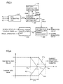
- Fig. 3 is a block diagram illustrating charge/discharge control of main battery 310 in hybrid vehicle 10.
- ECU 400 includes an SOC (State Of Charge) estimating unit 410, a charge/discharge limit setting unit 420, a battery temperature limitation map 430, a total power calculating unit 450, and a distribution control unit 460.
- SOC State Of Charge
- SOC estimating unit 410 generates SOC indicating the remaining capacity of main battery 310, at least partially based on battery temperature Tb, battery current Ib and battery voltage Vb of main battery 310. SOC typically is a percentage representation of the remaining capacity to the fully charged state.
- Charge/discharge limit setting unit 420 sets charge/discharge power upper limit values Win and Wout, mainly in accordance with the current SOC and battery temperature Tb. As will be described later, running of hybrid vehicle 10 is controlled such that charge/discharge of main battery 310 is within the range between Win and Wout.
- Charge/discharge limit setting unit 420 obtains charge/discharge limit values
- Win# and Wout# to cope with the increase in battery temperature, in accordance with battery temperature limitation map 430 storing temperature conditions of charge/discharge limitation with respect to the battery temperature. Then, charge/discharge limit setting unit 420 sets final charge/discharge power upper limit values Win and Wout, taking into consideration other factors such as SOC. Specifically, even if charge/discharge limitation is unnecessary from the viewpoint of battery temperature, the charge/discharge may be limited with absolute value of Win and Wout set low, considering other conditions such as SOC attaining closer to the upper/lower limit.
- Total power calculating unit 450 calculates the vehicle driving power and vehicle braking power required by hybrid vehicle 10 as a whole (PttI), based on the pedal operations by the driver including accelerator and brake operations and status of the vehicle such as the vehicle speed. Then, distribution control unit 460 generates MG request values to motor generators 300A and 300B and an output request value to engine 100 to satisfy the requested vehicle driving power or vehicle braking power, while limiting the charge/discharge of main battery 310 such that charge/discharge is executed within the possible charge/discharge range (Win to Wout) of main battery 310.
- Win to Wout possible charge/discharge range
- engine 100 is controlled by ECU 400 (engine ECU 406) such that it operates in accordance with the output request value. Further, ECU 400 (MG_ECU 402) controls up-converter 320 and inverter 330 such that motor generators 300A and 300B operate in accordance with the MG request values (typically, torque command values).
- MG_ECU 402 controls up-converter 320 and inverter 330 such that motor generators 300A and 300B operate in accordance with the MG request values (typically, torque command values).
- charge/discharge limitation based on battery temperature is not executed.
- the final values Win and Wout are set based on factors (such as SOC) other than the battery temperature, as described above.
- setting of upper limit values Win# and Wout# of charge/discharge power shown in Fig. 4 corresponds to control of start and degree (including charge/discharge inhibition as the severest limitation) of charge/discharge limitation of main battery 310 in accordance with the battery temperature increase. Though not shown in the figure as the present invention is focused on charge/discharge limitation to cope with the increase of battery temperature, actually the values Win# and Wout# may be set to limit charge/discharge of main battery 310 in a very low temperature range.
- battery temperature limitation map 430 includes a limitation map 434 used for catalyst warm-up period and a map 432 used for other periods, set separately. Maps 434 and 432 used for catalyst warm-up period and for other periods, respectively, are selectively referred to in accordance with a catalyst warm-up flag FWR.
- the catalyst warm-up flag FWR is turned on to request catalyst warm-up if the catalyst temperature is lower than a prescribed temperature when start of operation of engine 100 is requested, and once turned on, it is turned off when the catalyst temperature reaches the prescribed temperature (activating temperature).
- charge/discharge of main battery 310 is limited from a temperature range lower than in the catalyst warm-up period, in accordance with map 432 for the period other than the catalyst warm-up period.
- T1s and T1p to start limitation of charge/discharge power and to inhibit charge/discharge in the catalyst warm-up period are determined in accordance with battery characteristics of main battery 310.
- T1p corresponds to a management upper limit determined in consideration of deterioration of battery characteristics.
- T2s and T2p in the periods other than catalyst warm-up period are set to have margins ⁇ Ts (T1s - T2s) and ⁇ Tp (T1p - T2p) with respect to T1s and T1p.
- margins ⁇ Ts T1s - T2s
- T1p - T2p ⁇ Tp
- T1s corresponds to the "first temperature”
- T2s corresponds to the “second temperature”
- T1p corresponds to the “third temperature”
- T2p corresponds to the "fourth temperature.”
- limitation of charge/discharge means limitation of charge/discharge power and/or inhibition of charge/discharge.
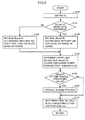
- Fig. 5 represents the process for setting an upper limit of charge/discharge power in the hybrid vehicle in accordance with an embodiment of the present invention.
- the series of processes shown in Fig. 5 corresponds to the function of charge/discharge limit setting unit 420 shown in Fig. 3 .
- ECU 400 obtains battery temperature Tb based on a signal from monitor unit 340, and at step S110, determines whether or not catalyst warm-up is in progress.
- the determination at step S110 may be made, for example, based on catalyst warm-up flag FWR.
- step S120 At which Win# and Wout# are set in accordance with map 432 ( Fig. 4 ) for periods other than the catalyst warm-up period.
- step S130 ECU 400 sets Win# and Wout# in accordance with map 434 ( Fig. 4 ) for catalyst warm-up period.
- step S130 corresponds to the step of setting the "first temperature condition”
- step S120 corresponds to the step of setting the "second temperature condition.”
- ECU 400 sets upper limits Win# and Wout# of charge/discharge power in accordance with battery temperature Tb, distinguishing the catalyst warm-up period and other period. Further, at step S150, ECU 400 determines whether or not the amount of change of upper limit values Win# or Wout# of charge/discharge power set at step S140 from the set values of the last control period is larger than a prescribed value.
- ECU 400 performs a gradual change process using, for example, a low-pass filter, so that the amount of change per unit time becomes equal to or smaller than the prescribed value (step S160). Specifically, when the catalyst warm-up is to be terminated or to be started, even if upper limit value Win# or Wout# of charge/discharge power calculated from map 432 or 434 momentarily changes significantly, actual time-change of upper limit of charge/discharge power can be made smooth.
- ECU 400 does not execute the gradual change process of step S160. In that case, upper limit values Win# and Wout# of charge/discharge power set at step S140 are directly used.
- ECU 400 sets the final upper limit values Win and Wout of charge/discharge power in consideration of factors other than the battery temperature as described above, in addition to the upper limit values Win# and Wout# of charge/discharge power based on battery temperature set through steps S100 to S160.
- the upper limit values Win# and Wout# of charge/discharge power based on battery temperature may be regarded as modification coefficients set in the range of 0 to 1.0, and the final upper limit values Win and Wout of charge/discharge power may be determined in accordance with products of the modification coefficients and basic upper limit values of charge/discharge power calculated in accordance with SOC.
- Fig. 6 shows an idea of charge/discharge limitation with respect to the battery temperature increase in accordance with a comparative example of an embodiment.
- charge/discharge is limited in accordance with battery characteristics of main battery 310 in all periods, not particularly distinguishing the catalyst warm-up period from other periods. Specifically, as in the example using map 434 for catalyst warm-up period shown in Fig. 4 , charge/discharge limitation of main battery 310 is executed to cope with the battery temperature increase, such that limitation of charge/discharge power starts when Tb > Tips, and charge/discharge is inhibited when Tb>T1p.
- Figs. 7 and 8 show exemplary battery temperature changes when charge/discharge is controlled in accordance with the charge/discharge limitation of Fig. 6.
- Fig. 7 shows temperature changes when cooling system 315 of main battery operates normally
- Fig. 8 shows temperature changes when cooling system failed.
- battery temperature Tb increases as main battery 3 10 is charged/discharged. It is noted, however, that because of the effect of cooling system 315, battery temperature Tb does not increase to such a temperature range (Tb > T1s) that requires limitation of charge/discharge power Pb from the viewpoint of battery temperature.
- battery temperature Tb When vehicle operation stops at t1, battery temperature Tb generally tends to decrease. Since main battery 310 is commonly mounted not to be exposed to the open air and has relatively high heat capacity, the battery temperature decreases relatively slowly while the vehicle is not operating. On the other hand, catalyst 140 ( Fig. 2 ) is usually arranged to be exposed to the open air and has small heat capacity. Therefore, the catalyst temperature decreases much faster than the battery temperature when the vehicle is not operating. Further, since engine 100 is operated intermittently in accordance with the state of running of hybrid vehicle 10, the temperature of catalyst 140 also decreases when the engine is stopped, even when the vehicle is operating.
- catalyst warm-up may possibly be required, depending on the length of time period (t 1 to t2) while the vehicle operation was stopped.
- step S160 Fig. 5
- main battery 310 is continuously charged until immediately before the start of vehicle operation (immediately before time point t2) by the external power source. If the limitation of charging power when the vehicle is externally charged is executed in accordance with the comparative example of Fig. 6 , battery temperature Tb may possibly reach the temperature T1s for starting charge/discharge limitation when catalyst warm-up starts at the start of vehicle operation, as in the case of Fig. 8 .
- appropriate catalyst warm-up cannot be executed from the same reason as described with reference to Fig. 8 and, therefore, exhaust emission undesirably increases.
- catalyst warm-up may be required when engine 100 is automatically stopped and then restarted during intermittent operation of engine 100. It is understood that, in this case also, battery temperature Tb may possibly reach the temperature T1s for starting charge/discharge limitation when catalyst warm-up starts, as in Fig. 8 .
- Fig. 9 shows exemplary battery temperature changes when charge/discharge is controlled in accordance with the charge/discharge limitation of an embodiment of the invention shown in Fig. 4 .
- battery temperature Tb at the start of catalyst warm-up (time point t2) can be set lower than the temperature T1s of starting limitation of charge/ discharge power in the catalyst warm-up period.
- catalyst warm-up can be executed in a normal manner without causing charge/discharge limitation of main battery 310.
- margins ⁇ Ts (T1s - T2s) and ⁇ Tp (T1p - T2p) shown in Fig. 4 are larger than the expected amount ⁇ Tw of temperature increase of main battery 310 in the catalyst warm-up period (time period from start to normal completion) with cooling system 315 failed, charge/discharge limitation of main battery 310 can more reliably be avoided in the catalyst warm-up period.
- the expected amount ⁇ Tw of temperature increase can be calculated, for example, by an experiment using an actual machine.
- the time necessary for catalyst warm-up is typically about one to two minutes and, therefore, the margins ⁇ Ts and ⁇ Tp are not very large. Therefore, as can be understood, availability of main battery 310 other than in the catalyst warm-up period is not much lowered.
- upper limit values Wout# and Win# of charge/discharge power are again set in accordance with map 432 ( Fig. 4 ) for the period other than the catalyst warm-up period, to be ready for the next catalyst warm-up.
- the gradual change process is executed regarding the time change of upper limit values Wout# and Win# of charge/discharge power.
- abrupt change in upper limit values of charge/discharge power can be reduced, enabling smooth vehicle behavior.
- the gradual change process of upper limit values of charge/discharge power at the start of catalyst warm-up may not be executed as shown at time point t2 of Fig. 9 , in order to execute catalyst warm-up with higher priority.
- conditions for gradual change may be changed at the start and end of catalyst warm-up, such that the time change at the start of catalyst warm-up becomes larger than the time change at the end of catalyst warm-up.
- the charging power is limited in accordance with map 432 for the period other than the catalyst warm-up period ( Fig. 4 ). Therefore, battery temperature Tb when catalyst warm-up is requested at the start of vehicle operation can be made lower than the temperature T1s of starting limitation of charge/discharge power in the catalyst warm-up period, as in the case of Fig. 9 .
- the "period other other than the catalyst warm-up period” encompasses the vehicle operation stopped period, in addition to the period in which catalyst warm-up is not executed during vehicle operation (including after the completion of catalyst warm-up).
- the battery temperature at which charge/discharge limitation starts in the period other than the catalyst warm-up period is set lower than the original value in accordance with battery characteristics, to be ready for the catalyst warm-up. Therefore, limitation of charge/discharge power resulting from increased battery temperature in the catalyst warm-up period can be prevented. As a result, battery protection for preventing excessive increase of battery temperature is reliably executed, while catalyst warm-up is executed in a normal manner without causing charge/discharge limitation of main battery 310, whereby worsening of exhaust characteristics can surely be prevented.
- cooling system 315 of main battery 310 should fail during or before the start of running and battery temperature tends to increase easily, vehicle running realizing battery protection and avoidance of worsening of exhaust characteristics as described above can be attained without stopping the hybrid system.
- the present embodiment has been described assuming that in the catalyst warm-up operation, basically the vehicle driving power is provided by the output of motor generator 300B and the output of engine 100 is reduced to the minimum value necessary for the catalyst warm-up. It is possible, however, to make shorter the time for catalyst warm-up by increasing the output of engine 100 using power generated by motor generator 300A (MG(1)), as proposed in PTL 1.
- MG(1) motor generator 300A
- ECU 400 determines whether or not catalyst warm-up is in progress, and if catalyst warm-up is being done (YES at step S200), at step S210, ECU 400 determines whether or not condition for executing catalyst warm-up with the engine output increased are satisfied.
- the condition for determination may be defined such that the determination at step S210 is YES if SOC of main battery 310 is low, or if battery temperature has reached the range that requires limitation of charge/discharge.
- step S220 ECU 400 generates regenerative torque of motor generator 300A (MG(1)) in the catalyst warm-up period, so that the output of engine 100 is increased.
- MG(1) motor generator 300A
- heat quantity of exhaust gas transmitted to catalyst 140 ( Fig. 2 ) increases and, therefore, catalyst warm-up can be completed in a shorter time period.
- step S210 ECU 400 skips step S220.
- the output of engine 100 is reduced to minimum amount necessary for catalyst warm-up.
- appropriate operating condition for catalyst warm up can be set in accordance with the vehicle state at the time of catalyst warm-up.
- regenerative torque of motor generator 300B may be generated in accordance with the process of step S220 uniformly to increase the output of engine 100, without switching the operating condition as shown in Fig. 10 .
- the time for catalyst warm-up becomes shorter and the increase in battery temperature in the catalyst warm-up period can be reduced. Therefore, margins ⁇ Ts and ⁇ Tp shown in Fig. 4 can be made smaller.
- main battery 310 can be utilized more efficiently in periods other than the catalyst warm-up period.
- the present invention is applicable to a hybrid vehicle mounting an engine and an electric motor generating vehicle driving power by electric power from a power storage device.
Landscapes
- Engineering & Computer Science (AREA)
- Transportation (AREA)
- Mechanical Engineering (AREA)
- Chemical & Material Sciences (AREA)
- Combustion & Propulsion (AREA)
- Power Engineering (AREA)
- Sustainable Development (AREA)
- Sustainable Energy (AREA)
- Life Sciences & Earth Sciences (AREA)
- Automation & Control Theory (AREA)
- Hybrid Electric Vehicles (AREA)
- Electric Propulsion And Braking For Vehicles (AREA)
- Exhaust Gas After Treatment (AREA)
Applications Claiming Priority (1)
| Application Number | Priority Date | Filing Date | Title |
|---|---|---|---|
| PCT/JP2009/054250 WO2010100748A1 (ja) | 2009-03-06 | 2009-03-06 | ハイブリッド車両の制御装置および制御方法 |
Publications (1)
| Publication Number | Publication Date |
|---|---|
| EP2404802A1 true EP2404802A1 (de) | 2012-01-11 |
Family
ID=42709326
Family Applications (1)
| Application Number | Title | Priority Date | Filing Date |
|---|---|---|---|
| EP09841111A Withdrawn EP2404802A1 (de) | 2009-03-06 | 2009-03-06 | Hybridfahrzeugsteuervorrichtung und steuerverfahren |
Country Status (5)
| Country | Link |
|---|---|
| US (1) | US20110320082A1 (de) |
| EP (1) | EP2404802A1 (de) |
| JP (1) | JPWO2010100748A1 (de) |
| CN (1) | CN102341286A (de) |
| WO (1) | WO2010100748A1 (de) |
Cited By (3)
| Publication number | Priority date | Publication date | Assignee | Title |
|---|---|---|---|---|
| EP2808197A4 (de) * | 2012-01-23 | 2015-09-30 | Toyota Motor Co Ltd | Fahrzeug und fahrzeugsteuerungsverfahren |
| EP3012140A1 (de) * | 2014-10-22 | 2016-04-27 | Toyota Jidosha Kabushiki Kaisha | Hybridfahrzeug |
| EP3943328A2 (de) * | 2020-07-01 | 2022-01-26 | Cummins Inc. | Systeme und verfahren zur leistungsverwaltung unter verwendung eines adaptiven leistungsteilungsverhältnisses |
Families Citing this family (28)
| Publication number | Priority date | Publication date | Assignee | Title |
|---|---|---|---|---|
| US8924057B2 (en) * | 2010-03-19 | 2014-12-30 | GM Global Technology Operations LLC | Method for starting a hybrid vehicle |
| JP5447245B2 (ja) * | 2010-07-13 | 2014-03-19 | 日産自動車株式会社 | ハイブリッド車両 |
| FR2967303B1 (fr) * | 2010-11-05 | 2013-04-12 | Renault Sa | Procede de charge pour une batterie d'alimentation d'un moteur d'entrainement d'un vehicule automobile |
| JP5110155B2 (ja) * | 2010-11-24 | 2012-12-26 | トヨタ自動車株式会社 | 車両用制御装置および車両用制御方法 |
| US9252622B2 (en) * | 2010-12-13 | 2016-02-02 | Panasonic Intellectual Property Management Co., Ltd. | Charging apparatus, power storage apparatus, and power source apparatus |
| JP5923944B2 (ja) * | 2011-01-25 | 2016-05-25 | 日産自動車株式会社 | ハイブリッド車両の制御装置 |
| JP5747533B2 (ja) * | 2011-02-02 | 2015-07-15 | コベルコ建機株式会社 | 旋回式作業機械 |
| JP5708178B2 (ja) * | 2011-04-13 | 2015-04-30 | トヨタ自動車株式会社 | 車両の制御装置 |
| JP2013001372A (ja) * | 2011-06-22 | 2013-01-07 | Toyota Motor Corp | ハイブリッド車両の制御装置およびそれを備えるハイブリッド車両、ならびにハイブリッド車両の制御方法 |
| WO2013018282A1 (ja) * | 2011-07-29 | 2013-02-07 | 三洋電機株式会社 | スイッチング装置、それを用いた太陽光発電システムおよび車両駆動システム |
| CN104136251B (zh) * | 2012-02-28 | 2017-03-08 | 丰田自动车株式会社 | 混合动力车辆的控制装置 |
| US8661800B2 (en) * | 2012-04-09 | 2014-03-04 | Ford Global Technologies, Llc | Method of collection and reuse of exhaust heat in a diesel-powered vehicle |
| JP6107349B2 (ja) * | 2013-04-11 | 2017-04-05 | スズキ株式会社 | バッテリ充放電制御装置 |
| JP6119600B2 (ja) * | 2013-12-25 | 2017-04-26 | 株式会社デンソー | ハイブリッド車制御装置 |
| JP6168029B2 (ja) * | 2014-11-13 | 2017-07-26 | トヨタ自動車株式会社 | 燃料電池搭載車両の外部給電システムの制御方法、および、外部給電システム |
| JP6496163B2 (ja) * | 2015-03-03 | 2019-04-03 | 日立建機株式会社 | ハイブリッド式建設機械 |
| JP6376169B2 (ja) * | 2016-04-20 | 2018-08-22 | トヨタ自動車株式会社 | ハイブリッド車両 |
| JP2018204496A (ja) * | 2017-06-01 | 2018-12-27 | 株式会社やまびこ | エンジン作業機 |
| DE102017210747A1 (de) * | 2017-06-27 | 2018-12-27 | Bayerische Motoren Werke Aktiengesellschaft | Verfahren zum Vorwärmen einer Batterie eines elektrisch betriebenen Kraftfahrzeugs sowie Ladevorrichtung |
| JP6936387B2 (ja) * | 2018-03-28 | 2021-09-15 | 本田技研工業株式会社 | 自動二輪車 |
| US11167745B2 (en) * | 2018-04-19 | 2021-11-09 | Toyota Jidosha Kabushiki Kaisha | Control system of hybrid vehicle |
| JP7272261B2 (ja) * | 2019-09-10 | 2023-05-12 | トヨタ自動車株式会社 | ハイブリッド車両 |
| US11305752B2 (en) * | 2019-11-01 | 2022-04-19 | GM Global Technology Operations LLC | Method and apparatus for emissions mitigation on a hybrid vehicle |
| CN111949006B (zh) * | 2020-07-31 | 2021-07-16 | 佛山市飞驰汽车科技有限公司 | 氢燃料电池车辆散热系统故障的检测判定方法 |
| CN114940156A (zh) * | 2021-02-08 | 2022-08-26 | 广汽埃安新能源汽车有限公司 | 电池soc调节处理方法、装置、控制器及存储介质 |
| JP7480739B2 (ja) * | 2021-04-20 | 2024-05-10 | トヨタ自動車株式会社 | ハイブリッド車両の制御装置 |
| JP7600842B2 (ja) * | 2021-04-21 | 2024-12-17 | 株式会社豊田自動織機 | ハイブリッド車両 |
| CN114435335B (zh) * | 2022-02-09 | 2023-12-15 | 浙江吉利控股集团有限公司 | 混合动力车辆的动力系统控制方法、控制系统及车辆 |
Family Cites Families (9)
| Publication number | Priority date | Publication date | Assignee | Title |
|---|---|---|---|---|
| US6330925B1 (en) * | 1997-01-31 | 2001-12-18 | Ovonic Battery Company, Inc. | Hybrid electric vehicle incorporating an integrated propulsion system |
| US6203468B1 (en) * | 1998-11-18 | 2001-03-20 | Fuji Jukogyo Kabushiki Kaisha | Control device for hybrid vehicle and method thereof |
| JP3566147B2 (ja) * | 1999-09-14 | 2004-09-15 | 本田技研工業株式会社 | ハイブリッド車両の冷却ファン故障検知装置 |
| JP3732395B2 (ja) | 2000-09-18 | 2006-01-05 | 株式会社日立製作所 | 車両の制御装置 |
| JP3933096B2 (ja) * | 2003-06-03 | 2007-06-20 | トヨタ自動車株式会社 | 車両に搭載されたバッテリ制御装置および制御方法 |
| JP4552921B2 (ja) * | 2006-10-25 | 2010-09-29 | トヨタ自動車株式会社 | ハイブリッド車およびその制御方法 |
| JP4183013B1 (ja) * | 2007-05-15 | 2008-11-19 | トヨタ自動車株式会社 | 車両およびその制御方法 |
| JP4228086B1 (ja) * | 2007-08-09 | 2009-02-25 | トヨタ自動車株式会社 | 車両 |
| JP4396756B2 (ja) * | 2007-10-11 | 2010-01-13 | トヨタ自動車株式会社 | 動力出力装置およびこれを備える車両ならびに動力出力装置の制御方法 |
-
2009
- 2009-03-06 EP EP09841111A patent/EP2404802A1/de not_active Withdrawn
- 2009-03-06 JP JP2011502550A patent/JPWO2010100748A1/ja active Pending
- 2009-03-06 US US13/254,349 patent/US20110320082A1/en not_active Abandoned
- 2009-03-06 WO PCT/JP2009/054250 patent/WO2010100748A1/ja not_active Ceased
- 2009-03-06 CN CN2009801578980A patent/CN102341286A/zh active Pending
Non-Patent Citations (1)
| Title |
|---|
| See references of WO2010100748A1 * |
Cited By (6)
| Publication number | Priority date | Publication date | Assignee | Title |
|---|---|---|---|---|
| EP2808197A4 (de) * | 2012-01-23 | 2015-09-30 | Toyota Motor Co Ltd | Fahrzeug und fahrzeugsteuerungsverfahren |
| US9522601B2 (en) | 2012-01-23 | 2016-12-20 | Toyota Jidosha Kabushiki Kaisha | Vehicle and method of controlling vehicle |
| EP3012140A1 (de) * | 2014-10-22 | 2016-04-27 | Toyota Jidosha Kabushiki Kaisha | Hybridfahrzeug |
| US9821794B2 (en) | 2014-10-22 | 2017-11-21 | Toyota Jidosha Kabushiki Kaisha | Hybrid vehicle |
| EP3943328A2 (de) * | 2020-07-01 | 2022-01-26 | Cummins Inc. | Systeme und verfahren zur leistungsverwaltung unter verwendung eines adaptiven leistungsteilungsverhältnisses |
| EP3943328B1 (de) * | 2020-07-01 | 2026-05-06 | Cummins Inc. | Systeme und verfahren zur leistungsverwaltung unter verwendung eines adaptiven leistungsteilungsverhältnisses |
Also Published As
| Publication number | Publication date |
|---|---|
| JPWO2010100748A1 (ja) | 2012-09-06 |
| WO2010100748A1 (ja) | 2010-09-10 |
| US20110320082A1 (en) | 2011-12-29 |
| CN102341286A (zh) | 2012-02-01 |
Similar Documents
| Publication | Publication Date | Title |
|---|---|---|
| US20110320082A1 (en) | Hybrid vehicle controller and control method | |
| CN107972658B (zh) | 混合动力车辆 | |
| JP4911206B2 (ja) | 車両の制御装置および制御方法 | |
| EP2644469B1 (de) | Steuerungsvorrichtung und steuerverfahren für ein hybridfahrzeug | |
| US8972148B2 (en) | Vehicle, method and device for controlling engine | |
| CN103354784B (zh) | 车辆、用于车辆的控制装置和用于车辆的控制方法 | |
| JP5929699B2 (ja) | ハイブリッド車両の制御装置 | |
| CN108437970A (zh) | 混合动力车辆 | |
| EP2386744A1 (de) | Steuervorrichtung für fahrzeuge | |
| JP6424566B2 (ja) | ハイブリッド車両の制御装置 | |
| US20100058737A1 (en) | Control device and control method of hybrid vehicle | |
| JP5842899B2 (ja) | ハイブリッド車両、ハイブリッド車両の制御方法およびエンジンの制御装置 | |
| JP6996456B2 (ja) | 車両及び車両の制御方法 | |
| JP2011043089A (ja) | 車両の制御装置および制御方法 | |
| JP5580867B2 (ja) | 車両の発電制御装置 | |
| JP6361684B2 (ja) | ハイブリッド車両の制御装置 | |
| JP2014172531A (ja) | 内燃機関の制御装置 | |
| US12618347B2 (en) | Hybrid vehicle rapid catalyst exhaust cooling | |
| US12522198B2 (en) | Controller for hybrid electric vehicle and method for controlling hybrid electric vehicle | |
| JP5644649B2 (ja) | 車両の制御装置 | |
| JPH10201009A (ja) | ハイブリッド型電気自動車の発電制御装置 | |
| CN121947443A (zh) | 混合动力车辆的控制装置及控制方法 | |
| JP2025088591A (ja) | ハイブリッド車両の制御方法 | |
| JP2021115945A (ja) | ハイブリッド車両の制御装置 | |
| JP2017153328A (ja) | 制御装置 |
Legal Events
| Date | Code | Title | Description |
|---|---|---|---|
| PUAI | Public reference made under article 153(3) epc to a published international application that has entered the european phase |
Free format text: ORIGINAL CODE: 0009012 |
|
| 17P | Request for examination filed |
Effective date: 20111005 |
|
| AK | Designated contracting states |
Kind code of ref document: A1 Designated state(s): AT BE BG CH CY CZ DE DK EE ES FI FR GB GR HR HU IE IS IT LI LT LU LV MC MK MT NL NO PL PT RO SE SI SK TR |
|
| STAA | Information on the status of an ep patent application or granted ep patent |
Free format text: STATUS: THE APPLICATION HAS BEEN WITHDRAWN |
|
| 18W | Application withdrawn |
Effective date: 20120302 |