EP2405105A2 - Dampfturbinengehäuse - Google Patents
Dampfturbinengehäuse Download PDFInfo
- Publication number
- EP2405105A2 EP2405105A2 EP11173162A EP11173162A EP2405105A2 EP 2405105 A2 EP2405105 A2 EP 2405105A2 EP 11173162 A EP11173162 A EP 11173162A EP 11173162 A EP11173162 A EP 11173162A EP 2405105 A2 EP2405105 A2 EP 2405105A2
- Authority
- EP
- European Patent Office
- Prior art keywords
- section
- shell
- exhaust
- steam turbine
- steam
- Prior art date
- Legal status (The legal status is an assumption and is not a legal conclusion. Google has not performed a legal analysis and makes no representation as to the accuracy of the status listed.)
- Withdrawn
Links
- 238000005266 casting Methods 0.000 description 7
- 239000000463 material Substances 0.000 description 3
- 238000000034 method Methods 0.000 description 3
- 238000004519 manufacturing process Methods 0.000 description 2
- 238000011084 recovery Methods 0.000 description 2
- 238000010276 construction Methods 0.000 description 1
- 238000000605 extraction Methods 0.000 description 1
- 239000012530 fluid Substances 0.000 description 1
- 238000007789 sealing Methods 0.000 description 1
- 230000007704 transition Effects 0.000 description 1
- 238000003466 welding Methods 0.000 description 1
Images


Classifications
-
- F—MECHANICAL ENGINEERING; LIGHTING; HEATING; WEAPONS; BLASTING
- F01—MACHINES OR ENGINES IN GENERAL; ENGINE PLANTS IN GENERAL; STEAM ENGINES
- F01D—NON-POSITIVE DISPLACEMENT MACHINES OR ENGINES, e.g. STEAM TURBINES
- F01D25/00—Component parts, details, or accessories, not provided for in, or of interest apart from, other groups
- F01D25/24—Casings; Casing parts, e.g. diaphragms, casing fastenings
- F01D25/243—Flange connections; Bolting arrangements
-
- F—MECHANICAL ENGINEERING; LIGHTING; HEATING; WEAPONS; BLASTING
- F01—MACHINES OR ENGINES IN GENERAL; ENGINE PLANTS IN GENERAL; STEAM ENGINES
- F01D—NON-POSITIVE DISPLACEMENT MACHINES OR ENGINES, e.g. STEAM TURBINES
- F01D25/00—Component parts, details, or accessories, not provided for in, or of interest apart from, other groups
- F01D25/24—Casings; Casing parts, e.g. diaphragms, casing fastenings
-
- F—MECHANICAL ENGINEERING; LIGHTING; HEATING; WEAPONS; BLASTING
- F05—INDEXING SCHEMES RELATING TO ENGINES OR PUMPS IN VARIOUS SUBCLASSES OF CLASSES F01-F04
- F05D—INDEXING SCHEME FOR ASPECTS RELATING TO NON-POSITIVE-DISPLACEMENT MACHINES OR ENGINES, GAS-TURBINES OR JET-PROPULSION PLANTS
- F05D2220/00—Application
- F05D2220/30—Application in turbines
- F05D2220/31—Application in turbines in steam turbines
-
- F—MECHANICAL ENGINEERING; LIGHTING; HEATING; WEAPONS; BLASTING
- F05—INDEXING SCHEMES RELATING TO ENGINES OR PUMPS IN VARIOUS SUBCLASSES OF CLASSES F01-F04
- F05D—INDEXING SCHEME FOR ASPECTS RELATING TO NON-POSITIVE-DISPLACEMENT MACHINES OR ENGINES, GAS-TURBINES OR JET-PROPULSION PLANTS
- F05D2230/00—Manufacture
- F05D2230/20—Manufacture essentially without removing material
- F05D2230/21—Manufacture essentially without removing material by casting
-
- F—MECHANICAL ENGINEERING; LIGHTING; HEATING; WEAPONS; BLASTING
- F05—INDEXING SCHEMES RELATING TO ENGINES OR PUMPS IN VARIOUS SUBCLASSES OF CLASSES F01-F04
- F05D—INDEXING SCHEME FOR ASPECTS RELATING TO NON-POSITIVE-DISPLACEMENT MACHINES OR ENGINES, GAS-TURBINES OR JET-PROPULSION PLANTS
- F05D2240/00—Components
- F05D2240/10—Stators
- F05D2240/14—Casings or housings protecting or supporting assemblies within
Definitions
- the subject matter disclosed herein relates to a cast shell for steam turbine systems. Specifically, the subject matter disclosed herein relates to a high or intermediate-pressure portion of a cast shell for a steam turbine system, the high or intermediate-pressure portion of the shell having a portion including an oblate spherical cross-section.
- Steam turbine shells are components that encompass, for example, the high pressure (HP) and/or intermediate pressure (IP) sections of the steam turbine.
- HP high pressure
- IP intermediate pressure
- steam turbine shells hold the stationary steampath components in close proximity to the rotating steampath components.
- Nozzle connections included in the structural shell allow for the entry and exit of the working fluid (e.g., steam) from the shell.
- several portions of the shell are configured and contoured to provide efficient flow path transitions between the nozzles and steampath components.
- Traditional steam turbine shells include both inlet (or admission) sections and exhaust (or extraction) sections having a substantially concentric-shaped channel configured to surround a portion of the steampath sections of the turbine.
- the different sections of the combined turbine shell e.g., HP, IP, etc.
- an exhaust portion of a steam turbine shell system includes: an exhaust shell portion including: a first section having a semi-circular cross-section; an exhaust section contiguous with the first section, the exhaust section including an exhaust outlet; and a second section having an oblate spherical cross-section including a substantially unitary bottom portion, the second section configured to fluidly connect with the first section, wherein the first section and the second section form a continuous steam flow path.
- a first aspect of the invention includes a steam turbine apparatus comprising: an exhaust shell portion including: a first section having a semi-circular cross-section; an exhaust section contiguous with the first section, the exhaust section including an exhaust outlet; and a second section having an oblate spherical cross-section including a substantially unitary bottom portion, the second section configured to fluidly connect with the first section, wherein the first section and the second section form a continuous steam flow path.
- a second aspect of the invention includes a steam turbine system comprising: a rotor; a plurality of blades operably connected to the rotor; and a shell surrounding the rotor and the blades, the shell including: an exhaust shell portion including: a first section having a semi-circular cross-section; an exhaust section contiguous with the first section, the exhaust section including an exhaust outlet; and a second section having an oblate spherical cross-section including a substantially unitary bottom portion, the second section configured to fluidly connect with the first section, wherein the first section and the second section form a continuous steam flow path
- aspects of the invention provide for a steam turbine shell including an intermediate-pressure section having an oblate spherical cross-section.
- the oblate spherical section includes a substantially unitary bottom portion.
- Single shell steam turbine castings where the cast shell includes both the high-pressure and intermediate-pressure sections, may allow for reduced costs in, e.g., manufacturing, shipping and/or construction when compared to separate shell castings.
- the weight of the shell is completely supported by support arms located near axial ends of the shell.
- the shell's weight places mechanical stress great enough to produce significant deflection of the support bars while the steam turbine is in service.
- a substantial portion of the cost of materials for the steam turbine shell may be dedicated to the IP section.
- Aspects of the invention provide for a reduction in the weight of the shell (e.g., the shell's IP section).. These aspects may reduce the amount of material used in forming the shell, while still allowing the shell to be cast using conventional processes.
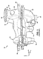
- FIG. 1 a three-dimensional perspective view of a prior art steam turbine shell 10 for, e.g., an opposed flow steam turbine is shown.
- steam turbine shell 10 may have a high-pressure (HP) section 12 including an HP inlet 14 and an HP exhaust outlet 16.
- HP inlet 14 may be configured to receive high-pressure steam from a steam source (e.g., a heat recovery steam generator, not shown), and guide that steam toward the high pressure section of a steam turbine partially enclosed therein to perform mechanical work by forcing rotation of turbine blades.
- steam may be guided through HP exhaust outlet 16, and provided to, e.g., a heat exchanger.
- Steam turbine shell 10 may also include an intermediate-pressure (IP) section 18 having an IP inlet 20, an IP exhaust outlet 22, and a nozzle connection (e.g., a low-pressure (LP) admission inlet) 24.
- IP intermediate-pressure
- a divider may be included in steam turbine shell 10 to divide HP section 12 and IP section 18.
- IP inlet 20 may be configured to receive intermediate pressure steam from a steam source (e.g., a heat recovery steam generator, not shown), and guide that steam toward the intermediate pressure section of the steam turbine to perform mechanical work by forcing rotation of turbine blades.
- IP exhaust outlet 22 After performing mechanical work in the intermediate pressure section of the steam turbine, a majority of this steam may be guided through IP exhaust outlet 22, and a second portion of this steam may be guided through nozzle connection (e.g., LP admission inlet) 24, where it may be supplied to, e.g., a LP section of the turbine (not shown).
- nozzle connection e.g., LP admission inlet
- Steam turbine shell 10 may also include support arms 26, which may be located at axial ends of the steam turbine shell 10.
- Steam turbine shell 10 may also include an intermediate-pressure shell portion (or simply, portion) 28 having an upper section 30 and a lower section 32.
- Steam turbine shell 10 may also include an exhaust section 34 contiguous with (e.g., cast along with) upper section 30.
- exhaust section 34 may include one or more nozzles or flanges cast integral with steam turbine shell 10 and oriented substantially transverse to an axis (direction "A" of the key in lower-left corner of FIG. 1 , axis omitted for clarity) of a steam turbine at least partially contained within steam turbine shell 10).
- Upper section 30 and lower section 32 may be substantially symmetrical about an axial plane, running parallel to the axis (A). That is, upper section 30 and lower section 32 may respectively have substantially semi-circular, symmetrical cross-sections (excluding exhaust section 34 and LP admission inlet 24, respectively), and may be configured to join at the axial plane (or, equatorial surface) running therebetween.
- This axial plane, or equatorial surface (E) may also be referred to herein as a "horizontal joint surface.” While the equatorial surface (E) is not visible from the three-dimensional perspective view of FIG. 1 , it is shown in the end views of the IP shell portion of FIGS. 2-3 , running between upper section 30 and lower section 32.
- equatorial surface (E) (or, axial plane) is used as a reference plane to aid in illustrating aspects of the invention.
- upper section 30 and lower section 32 may be formed via casting, and their symmetrical cross-sections may simplify the casting process.
- IP shell portion 28 of FIG. 1 is shown in a schematic end-view illustration.
- IP shell portion 28 may at least partially surround a steam turbine rotor (or simply, rotor) 36, which may have a plurality of blades or "buckets" attached thereto (blades omitted for clarity).
- Rotor 36 and its rotor blades may be surrounded by a diaphragm assembly (omitted for clarity), which may also be at least partially surrounded by IP shell portion 28.
- upper section 30 and lower section 32 may be substantially symmetrical about the equatorial plane (E), excluding exhaust section 34, and LP admission inlet 24.
- E equatorial plane
- a polar radius (rp) and a first equatorial radius (re) of IP shell portion 28 may have a substantially equal value ( FIG. 3 ).
- the distance from a central point of rotor 36 to an outer surface of lower section 32 along the equatorial (or axial) plane (E) is substantially the same as the distance from the central axial point of rotor 36 to an outer surface of lower section 32 along an axis (e.g., z-axis) perpendicular to the equatorial plane (E).
- axis e.g., z-axis
- lower section 32 includes a first equatorial radius (re) that is substantially equal to a polar radius (rp), meaning lower section 32 forms an approximately semi-circular shape with a horizontal joint surface abutting the equatorial plane (E).
- Lower section 32 is configured to fluidly connect with upper section 30, wherein upper section 30 and lower section 32 form a continuous steam flow channel, or path 40 (shown in FIG. 3 ).
- Continuous steam flow path 40 may have a substantially uniform radial depth (Rd). This radial depth may be measured as a radial distance from an innermost point in continuous flow path 40 to an outermost point in continuous flow path 40 (e.g., an inner wall of lower section 32) along a given radial line. As shown, radial depth (Rd) at or near an uppermost portion of lower section 32 is substantially equal to the radial depth (Rd) at or near a lowermost portion of lower section 32. That is, the substantially semi-circular lower section 32 of the prior art includes a steam flow path 40 having a substantially uniform radial depth (Rd).
- IP shell portion 28 may contribute a significant proportion of the weight of steam turbine shell 10. Additionally, IP shell portion 28 may require a significant amount of material to manufacture (e.g., using a casting process). Additionally, many portions of steam turbine shell 10 are subject to internal steam pressure and temperatures (thermal loads). The mechanical and thermal loads on many portions steam turbine shell 10 may cause it to deform (e.g., as a support beam deforms under load), which may cause design problems relating to clearances internal to steam turbine shell 10 (e.g., distances between rotating components of the steam turbine and the inner walls of steam turbine shell 10).
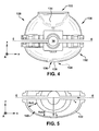
- exhaust shell portion (e.g., an IP exhaust shell portion) 128 is shown according to an embodiment.
- exhaust shell portion (IP exhaust shell portion) 128 includes a section (or, "second section", e.g., a lower section) 132 having an oblate spherical cross-section including a substantially unitary bottom portion 136. That is, lower section 132 and an upper section 134 (described further herein) are asymmetrical about an equatorial plane (E).
- equatorial plane E
- section 132 has an oblate spherical cross-section.
- oblate spherical describes the cross-section of lower section 132 according to embodiments.
- This oblate spherical cross-section may be defined in part by the relationship between a first equatorial radius (rea) and a polar radius (rp) of the geometric cross-section.
- rea first equatorial radius
- rp polar radius
- the distance from a central axial point of rotor 36 to an outer surface of section 132 along the equatorial (or axial) plane (E) is greater than the distance from the central point of rotor 36 to an the outer surface of section 132 along an axis (e.g., z-axis) perpendicular to the equatorial plane (E).
- axis e.g., z-axis
- this section 132 may have a three-dimensional shape substantially similar to half of a scalene ellipsoid.
- a scalene ellipsoid is a quadratic structure having two distinct equatorial radii, (rex), along the x-axis, and (rea), along the axial axis, and a polar radius (rp) distinct from both the equatorial radii.
- the radius of section 132 becomes progressively smaller as measured going away from the equatorial plane (E) along an outermost surface of section 132.
- section 132 may include a substantially unitary bottom portion 136.
- Substantially unitary bottom portion 136 may be devoid of a nozzle connection (e.g., an LP admission inlet such as LP admission inlet 24 of FIG. 2 , or an inlet connection) and may include a substantially flattened portion 138.
- Substantially flattened portion 138 may span a distance at least as great as the diameter of rotor 36, and may be substantially parallel to equatorial surface (E).
- substantially flattened portion 138 may be a shorter distance from the central axial point of rotor 36 than a bottom portion of an exhaust section 134 contiguous with a first section 130 (where exhaust section 134 is tapered at an exhaust outlet 122 away from first section 130).
- first section 130 may provide for a low-pressure (LP) admission inlet by diverting a portion of the exhaust steam provided to an intermediate-pressure exhaust outlet 122 to a low-pressure section of a steam turbine.
- section 132 may include a low-pressure (LP) admission inlet 124 (indicated in phantom) configured to emit approximately zero to approximately five percent of an amount of exhaust steam emitted from intermediate-pressure exhaust outlet 122.
- LP low-pressure
- multiple nozzle connections, or ports e.g., outlets or inlet ports
- multiple ports e.g., outlets or inlet ports
- second section 132 is configured to fluidly connect with first section 130, wherein first section 130 and second section 132 form a continuous steam flow channel, or path 140. That is, second section 132 and first section 130 may be joined along the equatorial surface (or, horizontal joint surface) (E) and substantially seal the steam turbine intermediate pressure section from an external environment. It is understood that lower section 132 and upper section 130 may be bound at horizontal joint surface (E) via, e.g., bolting, welding, and/or other sealing and binding methods known in the art. In accordance with embodiments of the invention, as shown in FIG.
- the steam channel 140 may have a greater radial depth (Rd1) at or near an uppermost portion of the lower shell section than at a lowermost portion of the lower shell section (having a distinct, smaller radial depth (Rd2)). That is, first section 130 and second section 132 may have substantially similar radial depths (Rd1) near the horizontal joint surface (E) such that when joined, first section 130 and second section 132 form a continuous flow path. However, as described herein, radial depth Rd2 will be distinct from, and smaller than, Rd1.
- an HP section of a steam turbine shell may include a first section having a semi-circular cross-section; and a second section having an oblate spherical cross-section including a substantially flattened portion, the second section configured to fluidly connect with the first section, wherein the first section and the second section form a continuous steam flow path.
- the first portion and the second portion may be asymmetric about the axial plane (or equatorial surface (E)), excluding the one or more inlet or exhaust sections.
- second section 132 (having oblate spherical cross-section) may be located vertically above (in the z-direction) first section 130. That is, the orientation shown and described with reference to FIGS. 4-5 may be "flipped", wherein second section 132 is located substantially vertically above rotor 36, and first section 130 is located substantially below rotor 36. It is further understood that in this embodiment, exhaust section 134 may be formed contiguous with second section 132 (e.g., via casting) and located vertically above first section 130. Other orientations are also possible, e.g., wherein the equatorial plane (E) is not substantially horizontal.
- FIG. 6 a partial cut-away view of the second section 132 of a shell portion is shown.
- This partial cut-away is shown cut along the axis of the rotor 36, showing approximately half of second section 132 below equatorial plane (E).
- This view illustrates the polar radius (rp) from a perspective inside section 132.
- optional LP admission inlet 124 which may include substantially flattened portion 138.
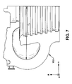
- FIG. 7 shows a partial cut away top view of the second section 132 of FIG. 6 .
- Equatorial radius (re) is shown spanning from an axial center line of a rotor (e.g., rotor 36, not shown) to the outer wall of flow channel (or, path) 140. It is understood, that according to embodiments herein, equatorial radius (re) may be approximately thirty three percent greater than polar radius (rp) ( FIG. 6 ).
Landscapes
- Engineering & Computer Science (AREA)
- Mechanical Engineering (AREA)
- General Engineering & Computer Science (AREA)
- Turbine Rotor Nozzle Sealing (AREA)
Applications Claiming Priority (1)
| Application Number | Priority Date | Filing Date | Title |
|---|---|---|---|
| US12/832,530 US8506245B2 (en) | 2010-07-08 | 2010-07-08 | Steam turbine shell |
Publications (2)
| Publication Number | Publication Date |
|---|---|
| EP2405105A2 true EP2405105A2 (de) | 2012-01-11 |
| EP2405105A3 EP2405105A3 (de) | 2014-04-23 |
Family
ID=44583988
Family Applications (1)
| Application Number | Title | Priority Date | Filing Date |
|---|---|---|---|
| EP11173162.6A Withdrawn EP2405105A3 (de) | 2010-07-08 | 2011-07-07 | Dampfturbinengehäuse |
Country Status (4)
| Country | Link |
|---|---|
| US (1) | US8506245B2 (de) |
| EP (1) | EP2405105A3 (de) |
| JP (1) | JP2012017737A (de) |
| RU (1) | RU2011127686A (de) |
Cited By (1)
| Publication number | Priority date | Publication date | Assignee | Title |
|---|---|---|---|---|
| EP3445953B1 (de) | 2016-04-18 | 2020-04-01 | MAN Energy Solutions SE | Strömungsmaschinengehäuse |
Families Citing this family (3)
| Publication number | Priority date | Publication date | Assignee | Title |
|---|---|---|---|---|
| CA2838431C (en) * | 2014-01-09 | 2015-03-31 | Shelly O'connor | Undergarment with discreet access opening |
| USD941360S1 (en) * | 2019-01-31 | 2022-01-18 | Elliott Company | Oval steam turbine casing |
| US11118479B2 (en) * | 2019-12-11 | 2021-09-14 | General Electric Company | Stress mitigating arrangement for working fluid dam in turbine system |
Family Cites Families (5)
| Publication number | Priority date | Publication date | Assignee | Title |
|---|---|---|---|---|
| US2278304A (en) * | 1940-07-30 | 1942-03-31 | Westinghouse Electric & Mfg Co | Joint construction |
| US4451219A (en) * | 1980-12-15 | 1984-05-29 | Kurherr Motoren A.G. | Valveless bi-chamber rotary steam engine with turbine effect |
| US7707011B2 (en) * | 2002-12-12 | 2010-04-27 | General Electric Company | Method to optimize pipe load limits on a turbine casing |
| EP2096273A1 (de) * | 2008-02-28 | 2009-09-02 | Siemens Aktiengesellschaft | Rohrförmiges Gehäuse für einen Abschnitt eines Druckgehäuses einer Turbomaschine |
| EP2189630A1 (de) * | 2008-11-19 | 2010-05-26 | Siemens Aktiengesellschaft | Gasturbine, Leitschaufelträger für eine solche Gasturbine und Gas- bzw. Dampfturbinenanlage mit einer solchen Gasturbine |
-
2010
- 2010-07-08 US US12/832,530 patent/US8506245B2/en not_active Expired - Fee Related
-
2011
- 2011-06-29 JP JP2011143632A patent/JP2012017737A/ja not_active Withdrawn
- 2011-07-07 EP EP11173162.6A patent/EP2405105A3/de not_active Withdrawn
- 2011-07-07 RU RU2011127686/06A patent/RU2011127686A/ru not_active Application Discontinuation
Non-Patent Citations (1)
| Title |
|---|
| None |
Cited By (1)
| Publication number | Priority date | Publication date | Assignee | Title |
|---|---|---|---|---|
| EP3445953B1 (de) | 2016-04-18 | 2020-04-01 | MAN Energy Solutions SE | Strömungsmaschinengehäuse |
Also Published As
| Publication number | Publication date |
|---|---|
| EP2405105A3 (de) | 2014-04-23 |
| US20120006026A1 (en) | 2012-01-12 |
| US8506245B2 (en) | 2013-08-13 |
| JP2012017737A (ja) | 2012-01-26 |
| RU2011127686A (ru) | 2013-01-20 |
Similar Documents
| Publication | Publication Date | Title |
|---|---|---|
| JP6833255B2 (ja) | 一体型チューブインマトリックス熱交換器 | |
| JP6924012B2 (ja) | 冷却通路を有するタービンバケット | |
| EP2685048B1 (de) | Gasturbinen-Rotorschaufel und Gasturbine | |
| RU2338888C2 (ru) | Способ изготовления компонента статора | |
| EP3106621B1 (de) | Strömungsleitende abdeckung für eine motorkomponente | |
| EP1548230B2 (de) | Schaufel mit gestalteten Stegen an der Abströmkante | |
| US9181808B2 (en) | Blade or vane for a turbomachine | |
| EP3124743A1 (de) | Leitschaufel und verfahren zur herstellung einer leitschaufel | |
| US9156114B2 (en) | Method for manufacturing turbine nozzle having non-linear cooling conduit | |
| US9885243B2 (en) | Turbine bucket having outlet path in shroud | |
| US8506245B2 (en) | Steam turbine shell | |
| EP4105442B1 (de) | Verbesserte kühlschemata für schaufeln von gasturbinenmotoren | |
| US10451089B2 (en) | Turbomachine blade | |
| EP3163025B1 (de) | Turbinenschaufel mit auslassöffnung in deckband | |
| CN107269323A (zh) | 密封燃气涡轮中的角部泄漏的密封件组件 | |
| EP3106248A1 (de) | Herstellung eines gehäuses mit einer nabe | |
| US9080462B2 (en) | Cooling structure for bearing housing of turbocharger | |
| EP3075960A1 (de) | Leitschaufeleinheit mit mehrfachprofil | |
| CN110017176A (zh) | 翼型 | |
| WO2016027509A1 (ja) | 燃焼器の筒、燃焼器の筒の製造方法、圧力容器 | |
| EP3486430A1 (de) | Integral geformte turbinenrotorstufe | |
| EP3623575B1 (de) | Abdeckung für schlangenförmige windungen für gasturbinenstatorschaufelbaugruppe | |
| CN108235693A (zh) | 用于制造涡轮机的壳体的方法 |
Legal Events
| Date | Code | Title | Description |
|---|---|---|---|
| AK | Designated contracting states |
Kind code of ref document: A2 Designated state(s): AL AT BE BG CH CY CZ DE DK EE ES FI FR GB GR HR HU IE IS IT LI LT LU LV MC MK MT NL NO PL PT RO RS SE SI SK SM TR |
|
| AX | Request for extension of the european patent |
Extension state: BA ME |
|
| PUAI | Public reference made under article 153(3) epc to a published international application that has entered the european phase |
Free format text: ORIGINAL CODE: 0009012 |
|
| PUAL | Search report despatched |
Free format text: ORIGINAL CODE: 0009013 |
|
| AK | Designated contracting states |
Kind code of ref document: A3 Designated state(s): AL AT BE BG CH CY CZ DE DK EE ES FI FR GB GR HR HU IE IS IT LI LT LU LV MC MK MT NL NO PL PT RO RS SE SI SK SM TR |
|
| AX | Request for extension of the european patent |
Extension state: BA ME |
|
| RIC1 | Information provided on ipc code assigned before grant |
Ipc: F01D 25/24 20060101AFI20140314BHEP |
|
| STAA | Information on the status of an ep patent application or granted ep patent |
Free format text: STATUS: THE APPLICATION IS DEEMED TO BE WITHDRAWN |
|
| 18D | Application deemed to be withdrawn |
Effective date: 20141024 |