EP2405116A2 - Baugruppe für ein Hilfsaggregatsgetriebe - Google Patents
Baugruppe für ein Hilfsaggregatsgetriebe Download PDFInfo
- Publication number
- EP2405116A2 EP2405116A2 EP11172290A EP11172290A EP2405116A2 EP 2405116 A2 EP2405116 A2 EP 2405116A2 EP 11172290 A EP11172290 A EP 11172290A EP 11172290 A EP11172290 A EP 11172290A EP 2405116 A2 EP2405116 A2 EP 2405116A2
- Authority
- EP
- European Patent Office
- Prior art keywords
- accessory
- gear
- gearbox
- spur
- spur gear
- Prior art date
- Legal status (The legal status is an assumption and is not a legal conclusion. Google has not performed a legal analysis and makes no representation as to the accuracy of the status listed.)
- Withdrawn
Links
Images

Classifications
-
- F—MECHANICAL ENGINEERING; LIGHTING; HEATING; WEAPONS; BLASTING
- F02—COMBUSTION ENGINES; HOT-GAS OR COMBUSTION-PRODUCT ENGINE PLANTS
- F02C—GAS-TURBINE PLANTS; AIR INTAKES FOR JET-PROPULSION PLANTS; CONTROLLING FUEL SUPPLY IN AIR-BREATHING JET-PROPULSION PLANTS
- F02C7/00—Features, components parts, details or accessories, not provided for in, or of interest apart form groups F02C1/00 - F02C6/00; Air intakes for jet-propulsion plants
- F02C7/32—Arrangement, mounting, or driving, of auxiliaries
-
- Y—GENERAL TAGGING OF NEW TECHNOLOGICAL DEVELOPMENTS; GENERAL TAGGING OF CROSS-SECTIONAL TECHNOLOGIES SPANNING OVER SEVERAL SECTIONS OF THE IPC; TECHNICAL SUBJECTS COVERED BY FORMER USPC CROSS-REFERENCE ART COLLECTIONS [XRACs] AND DIGESTS
- Y02—TECHNOLOGIES OR APPLICATIONS FOR MITIGATION OR ADAPTATION AGAINST CLIMATE CHANGE
- Y02T—CLIMATE CHANGE MITIGATION TECHNOLOGIES RELATED TO TRANSPORTATION
- Y02T50/00—Aeronautics or air transport
- Y02T50/60—Efficient propulsion technologies, e.g. for aircraft
-
- Y—GENERAL TAGGING OF NEW TECHNOLOGICAL DEVELOPMENTS; GENERAL TAGGING OF CROSS-SECTIONAL TECHNOLOGIES SPANNING OVER SEVERAL SECTIONS OF THE IPC; TECHNICAL SUBJECTS COVERED BY FORMER USPC CROSS-REFERENCE ART COLLECTIONS [XRACs] AND DIGESTS
- Y10—TECHNICAL SUBJECTS COVERED BY FORMER USPC
- Y10T—TECHNICAL SUBJECTS COVERED BY FORMER US CLASSIFICATION
- Y10T74/00—Machine element or mechanism
- Y10T74/19—Gearing
- Y10T74/19949—Teeth
- Y10T74/19963—Spur
Definitions
- the subject matter disclosed herein relates to gearboxes for aircraft. More specifically, the subject disclosure relates to connection of accessories to an aircraft gearbox.
- a gearbox transfers power from a main shaft of an aircraft engine to a number of engine and aircraft accessories.
- a typical suite of accessories may include an electrical generator, hydraulic pump, fuel pump, starter, and oil lubrication and scavenging pump.
- these accessories are connected to the gearbox via a coaxial spline between a gearbox gear and the gearbox. This means of connecting accessories to the gearbox forces the accessories to be located at a face of the gearbox where packaging space is limited. Further, because of the direct spline connection, speed of the accessory is determined by the gear speed of the gearbox. Also, locating the accessories on the face of the gearbox increases cantilevering and unequal moments on the gearbox faces requiring increased structural support for the gearbox faces, which increases weight of the gearbox.
- an accessory gearbox assembly for an aircraft includes one or more intermeshed gears disposed in an accessory gearbox housing and configured to transfer rotational energy from an engine core.
- An accessory component has an accessory spur gear located at least partially in the accessory gearbox housing. The accessory spur gear is meshed with a gear within the gearbox housing thereby transferring rotational energy from the gearbox to the accessory component.
- a method for providing rotational energy to an accessory component at an accessory gearbox includes providing rotational energy to one or more intermeshed gears of an accessory gearbox and locating an accessory component at the accessory gearbox.
- the gearbox component includes a spur gear disposed at least partially in an accessory housing.
- the spur gear is meshed with a gear of the one or more gears and rotational energy is transferred from the one or more gears to the accessory component via the spur gear.
- FIG. 1 is a schematic view of an embodiment of an accessory gearbox for an aircraft
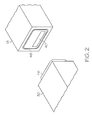
- FIG. 2 is an exploded view of an embodiment of a seal configuration for a gearbox
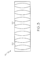
- FIG. 3 is a schematic view of a crowned gear interface for a gearbox.
- FIG. 1 Shown in FIG. 1 is a schematic view of an accessory gearbox 10 for an aircraft.
- the gearbox 10 is connected to an engine core 12 via a power transfer shaft 14. Rotational energy from the engine core 12 is transferred to the gearbox 10 via the transfer shaft 14 and drives one or more gears 16 in the gearbox 10.
- the gears 16 of the gearbox 10 may be intermeshed and are contained in a gearbox housing 18. As shown in FIG. 1 , the gears 16 are disposed such that their axes of rotation 20 are substantially parallel. It is to be appreciated that other arrangements of the gears 16 of the gearbox 10 are contemplated within the present scope.
- the gearbox 10 is configured to provide rotational energy to one or more accessory components 22 in operable communication with the gearbox 10.
- the accessory components 22 may be, for example, a fuel pump, lubrication pump, a hydraulic pump, or a cooling fan.
- at least one of the accessory components 22 is located at a longitudinal end 24 of the gear box 10, the longitudinal end 24 herein defined as a surface of the gearbox 10 substantially parallel to the axes of rotation 20 of the gears 16 as opposed to a face 26 of the gearbox 10 herein defined as a surface of the gearbox 10 substantially perpendicular to the axes of rotation 20 of the gears 16.
- the accessory component 22 is operably connected to the gearbox 10 via a spur gear 28, which rotates about spur axis 32.
- One of the gearbox gears 16 is disposed at least partially within an accessory housing 30.
- the spur gear 28 has a plurality of spur teeth 34 that extend toward a plurality of gear teeth 36 of one of the gears 16 and mesh therewith.
- the spur gear 28 meshes with the gear 16 such that rotation of the gear 16 drives rotation of the spur gear 28, which in turn drives rotation of an accessory shaft 38 to provide power to the accessory component 22.
- the spur axis 32 of rotation is substantially parallel to a gear axis 20 of rotation of the gear 16 with which the spur gear 28 is meshed.
- connection of the accessory component 22 to the gearbox 10 via the spur gear 28 allows for simple adjustment of the rotational speed of the spur gear 28 and therefore the rotational energy provided to the accessory component 22 by changing the number of spur teeth 34 in the spur gear 28 or by changing the number of gear teeth 36 in the gear 16 with which the spur gear 28 meshes.
- the gearbox housing 18 includes a gear opening 40 in the longitudinal end 24 and the accessory housing 30 includes a complimentary spur opening 42 to allow one of the gearbox gears 16 and the accessory spur gear 28 to extend therethrough and to mesh.
- a seal is provided between the accessory component 22 and the gearbox 10.
- the seal may be an seal plate 46 disposed at the accessory housing 30 surrounding the spur opening 42 which extends into a complimentary seal groove 48 surrounding the gear opening 40 in the gearbox housing 18. While the embodiment of FIG. 2 includes the seal plate 46 disposed at the accessory housing 30, it is to be appreciated that in other embodiments the interface between the gearbox housing 10 and the accessory housing 30 may be sealed by other means such as a gasket or formed elastomer.
- one or more of the gears 16 and the spur gear 28 may be configured with a crowned shape. Crowning describes a curvature of faces of gear teeth 50. The crowned shape prevents the gear teeth 50 from being point/line loaded when contacting the mating gear.
- locating the accessory component 22 at the longitudinal end 24 reduces the cantilever forces on the face 26 of the gearbox 10. Further, the accessory component 22 positioned at the longitudinal end 24 distributes accessory component 22 moment reaction evenly between the faces 26 of the gearbox 10. These factors allow the gearbox 10 and gearbox housing 18 to be constructed more lightly.
Landscapes
- Engineering & Computer Science (AREA)
- Chemical & Material Sciences (AREA)
- Combustion & Propulsion (AREA)
- Mechanical Engineering (AREA)
- General Engineering & Computer Science (AREA)
- General Details Of Gearings (AREA)
Applications Claiming Priority (1)
| Application Number | Priority Date | Filing Date | Title |
|---|---|---|---|
| US12/831,595 US20120006137A1 (en) | 2010-07-07 | 2010-07-07 | Gear driven accessory for gearbox |
Publications (1)
| Publication Number | Publication Date |
|---|---|
| EP2405116A2 true EP2405116A2 (de) | 2012-01-11 |
Family
ID=44582153
Family Applications (1)
| Application Number | Title | Priority Date | Filing Date |
|---|---|---|---|
| EP11172290A Withdrawn EP2405116A2 (de) | 2010-07-07 | 2011-06-30 | Baugruppe für ein Hilfsaggregatsgetriebe |
Country Status (4)
| Country | Link |
|---|---|
| US (1) | US20120006137A1 (de) |
| EP (1) | EP2405116A2 (de) |
| JP (1) | JP2012017740A (de) |
| CA (1) | CA2745014A1 (de) |
Cited By (6)
| Publication number | Priority date | Publication date | Assignee | Title |
|---|---|---|---|---|
| EP2522832A1 (de) * | 2011-05-09 | 2012-11-14 | United Technologies Corporation | Axialer Hilfsgeräteantrieb |
| US8490410B2 (en) | 2010-11-17 | 2013-07-23 | United Technologies Corporation | Axial accessory gearbox |
| US8490411B2 (en) | 2010-11-17 | 2013-07-23 | United Technologies Corporation | Axial accessory gearbox |
| WO2015004387A1 (fr) * | 2013-07-10 | 2015-01-15 | Hispano Suiza | Intégration d'un train d'engrenages dans un voile de pignon de boîtier d'entraînement pour turbomachine |
| WO2015004385A1 (fr) * | 2013-07-10 | 2015-01-15 | Hispano Suiza | Structure compacte de boitier d'entrainement pour turbomachine d'aeronef |
| WO2015052430A1 (fr) | 2013-10-11 | 2015-04-16 | Hispano Suiza | Boitier d'entrainement d'accessoires pour turbomachine |
Families Citing this family (7)
| Publication number | Priority date | Publication date | Assignee | Title |
|---|---|---|---|---|
| US8876476B2 (en) * | 2010-11-16 | 2014-11-04 | Hamilton Sundstrand Corporation | Integrated accessory gearbox and engine starter |
| FR2997467B1 (fr) * | 2012-10-26 | 2016-07-29 | Hispano Suiza Sa | Boite d'engrenages de prise de mouvement sur une turbomachine, composee de carter assemble |
| FR3007462B1 (fr) * | 2013-06-21 | 2017-11-24 | Hispano-Suiza | Boitier d'accessoires de turbomachine equipe d'une pompe centrifuge |
| US9611787B2 (en) | 2015-05-18 | 2017-04-04 | General Electric Company | Accessory apparatus and method of assembling accessories with a turbine engine |
| FR3038954B1 (fr) * | 2015-07-16 | 2017-07-21 | Airbus Helicopters | Boite de transmission de puissance et aeronef |
| FR3070726B1 (fr) * | 2017-09-07 | 2019-08-23 | Safran Transmission Systems | Boitier d'accessoires pour turbomachine |
| US11168577B2 (en) * | 2018-10-24 | 2021-11-09 | Hamilton Sundstrand Corporation | Gearbox ratio change |
Family Cites Families (8)
| Publication number | Priority date | Publication date | Assignee | Title |
|---|---|---|---|---|
| US1594516A (en) * | 1923-10-19 | 1926-08-03 | Du Pont | Agitating device |
| US2682760A (en) * | 1950-04-18 | 1954-07-06 | American Flexible Coupling Com | Gear coupling |
| JPH0447391Y2 (de) * | 1985-09-25 | 1992-11-09 | ||
| US5309708A (en) * | 1988-06-03 | 1994-05-10 | Alliedsignal Inc. | Multifunction integrated power unit |
| JPH0472429A (ja) * | 1990-07-13 | 1992-03-06 | Honda Motor Co Ltd | ガスタービンエンジン |
| WO2005073540A1 (en) * | 2004-01-30 | 2005-08-11 | Pratt & Whitney Canada Corp. | Compact configuration for attaching a fuel pump or other accessory to an accessory gearbox |
| JP4367948B2 (ja) * | 2005-08-05 | 2009-11-18 | 本田技研工業株式会社 | 一体成形ギヤ及び内燃機関用キック始動装置 |
| FR2894621B1 (fr) * | 2005-12-09 | 2011-10-14 | Hispano Suiza Sa | Systeme d'entrainement de machines auxiliaires d'un turbomoteur a double corps |
-
2010
- 2010-07-07 US US12/831,595 patent/US20120006137A1/en not_active Abandoned
-
2011
- 2011-06-28 CA CA2745014A patent/CA2745014A1/en not_active Abandoned
- 2011-06-30 EP EP11172290A patent/EP2405116A2/de not_active Withdrawn
- 2011-07-07 JP JP2011150541A patent/JP2012017740A/ja not_active Ceased
Non-Patent Citations (1)
| Title |
|---|
| None |
Cited By (15)
| Publication number | Priority date | Publication date | Assignee | Title |
|---|---|---|---|---|
| US8490410B2 (en) | 2010-11-17 | 2013-07-23 | United Technologies Corporation | Axial accessory gearbox |
| US8490411B2 (en) | 2010-11-17 | 2013-07-23 | United Technologies Corporation | Axial accessory gearbox |
| EP2522832A1 (de) * | 2011-05-09 | 2012-11-14 | United Technologies Corporation | Axialer Hilfsgeräteantrieb |
| FR3008463A1 (fr) * | 2013-07-10 | 2015-01-16 | Hispano Suiza Sa | Structure compacte de boitier d'entrainement pour turbomachine d'aeronef |
| WO2015004385A1 (fr) * | 2013-07-10 | 2015-01-15 | Hispano Suiza | Structure compacte de boitier d'entrainement pour turbomachine d'aeronef |
| FR3008462A1 (fr) * | 2013-07-10 | 2015-01-16 | Hispano Suiza Sa | Integration d'un train d'engrenages dans un voile de pignon de boitier d'entrainement pour turbomachine |
| WO2015004387A1 (fr) * | 2013-07-10 | 2015-01-15 | Hispano Suiza | Intégration d'un train d'engrenages dans un voile de pignon de boîtier d'entraînement pour turbomachine |
| CN105378336A (zh) * | 2013-07-10 | 2016-03-02 | 伊斯帕诺-絮扎公司 | 将齿轮链并入涡轮机齿轮箱的小齿轮壁中 |
| RU2674299C2 (ru) * | 2013-07-10 | 2018-12-06 | Испано Сюиза | Компактная конструкция вспомогательной коробки передач газотурбинного двигателя летательного аппарата |
| RU2679747C2 (ru) * | 2013-07-10 | 2019-02-12 | Сафран Трансмишн Системз | Встраивание системы зубчатых колес в стенку шестерни коробки приводов для газотурбинного двигателя |
| US10233998B2 (en) | 2013-07-10 | 2019-03-19 | Safran Transmission Systems | Incorporation of a gear train in a pinion wall in a gearbox for a turbomachine |
| CN105378336B (zh) * | 2013-07-10 | 2019-04-09 | 伊斯帕诺-絮扎公司 | 将齿轮链并入涡轮机齿轮箱的小齿轮壁中 |
| US10323576B2 (en) | 2013-07-10 | 2019-06-18 | Safran Transmission Systems | Compact structure for accessory gearbox of an aircraft turbine engine |
| EP3527844A1 (de) * | 2013-07-10 | 2019-08-21 | Safran Transmission Systems | Integration eines getriebes in eine getrieberadbahn eines getriebegehäuses für turbotriebwerk |
| WO2015052430A1 (fr) | 2013-10-11 | 2015-04-16 | Hispano Suiza | Boitier d'entrainement d'accessoires pour turbomachine |
Also Published As
| Publication number | Publication date |
|---|---|
| CA2745014A1 (en) | 2012-01-07 |
| JP2012017740A (ja) | 2012-01-26 |
| US20120006137A1 (en) | 2012-01-12 |
Similar Documents
| Publication | Publication Date | Title |
|---|---|---|
| EP2405116A2 (de) | Baugruppe für ein Hilfsaggregatsgetriebe | |
| US10323576B2 (en) | Compact structure for accessory gearbox of an aircraft turbine engine | |
| JP6005738B2 (ja) | 結合解除手段を組み込んだガスタービンアクセサリギアボックス | |
| EP1717489A2 (de) | Umlaufräderüber- oder Untersetzungsgetriebe zur Verwendung in Windturbinen und dergleichen | |
| US10352250B2 (en) | Equipment support of a turbo machine comprising a reducer with magnetic gears | |
| RU2666265C2 (ru) | Коробка приводов | |
| EP1921344A2 (de) | Integrierte Drehzahlwechsleranordnung | |
| US9726149B2 (en) | Spiral bevel gear set for ram air turbine | |
| KR20140115319A (ko) | 내치 링기어 및 이와 맞물리는 2개의 스퍼 기어들을 구비한 변속기 장치 | |
| JP6621471B2 (ja) | コンパクトな脊柱状トランスミッション | |
| EP2939929A1 (de) | Mehrachsige zubehörgetriebe mechanischer antriebssysteme und gasturbinenmotoren damit | |
| EP3065275B1 (de) | Gasturbinenmotor mit magnetischem getriebe | |
| US20150192110A1 (en) | Wind turbine gearbox | |
| US20100231098A1 (en) | Electric machine comprising an elastic connection to a gearbox primary shaft | |
| CN206478209U (zh) | 变速器及设有所述变速器的压缩机设备 | |
| RU2641777C2 (ru) | Шестеренчатая коробка передач для отбора мощности на газотурбинном двигателе, состоящая из кинематической цепи с линиями зацепления, расположенными в непараллельных плоскостях | |
| US10112483B2 (en) | Hydraulic pump assembly with forward driveshaft clearance | |
| US20150114154A1 (en) | Device for decelerating and reversing ship | |
| CN103032544A (zh) | 一种软启动齿轮箱 | |
| WO2011072601A1 (en) | Geared drive system with load sharing | |
| CN102767592A (zh) | 少齿差啮合式齿轮减速器 | |
| RU2377455C1 (ru) | Волновой привод | |
| CN211175241U (zh) | 一种变速箱 | |
| JP6798180B2 (ja) | 動力取出装置 | |
| RU149787U1 (ru) | Редуктор привода генератора |
Legal Events
| Date | Code | Title | Description |
|---|---|---|---|
| AK | Designated contracting states |
Kind code of ref document: A2 Designated state(s): AL AT BE BG CH CY CZ DE DK EE ES FI FR GB GR HR HU IE IS IT LI LT LU LV MC MK MT NL NO PL PT RO RS SE SI SK SM TR |
|
| AX | Request for extension of the european patent |
Extension state: BA ME |
|
| PUAI | Public reference made under article 153(3) epc to a published international application that has entered the european phase |
Free format text: ORIGINAL CODE: 0009012 |
|
| STAA | Information on the status of an ep patent application or granted ep patent |
Free format text: STATUS: THE APPLICATION HAS BEEN WITHDRAWN |
|
| 18W | Application withdrawn |
Effective date: 20140320 |