EP2405221A2 - Vorrichtung zum Anbringen von Verankerungsziegeln für Schamottsteine - Google Patents
Vorrichtung zum Anbringen von Verankerungsziegeln für Schamottsteine Download PDFInfo
- Publication number
- EP2405221A2 EP2405221A2 EP11173196A EP11173196A EP2405221A2 EP 2405221 A2 EP2405221 A2 EP 2405221A2 EP 11173196 A EP11173196 A EP 11173196A EP 11173196 A EP11173196 A EP 11173196A EP 2405221 A2 EP2405221 A2 EP 2405221A2
- Authority
- EP
- European Patent Office
- Prior art keywords
- fittings
- connecting arms
- fitting
- retaining
- corrugations
- Prior art date
- Legal status (The legal status is an assumption and is not a legal conclusion. Google has not performed a legal analysis and makes no representation as to the accuracy of the status listed.)
- Withdrawn
Links
- 239000011449 brick Substances 0.000 title claims description 39
- 239000011819 refractory material Substances 0.000 claims description 7
- 238000004873 anchoring Methods 0.000 description 13
- 239000002184 metal Substances 0.000 description 4
- 230000000694 effects Effects 0.000 description 2
- 238000003466 welding Methods 0.000 description 2
- 229910045601 alloy Inorganic materials 0.000 description 1
- 239000000956 alloy Substances 0.000 description 1
- 238000006073 displacement reaction Methods 0.000 description 1
- 230000014759 maintenance of location Effects 0.000 description 1
- 239000000463 material Substances 0.000 description 1
- 229910001092 metal group alloy Inorganic materials 0.000 description 1
- 230000000717 retained effect Effects 0.000 description 1
Images


Classifications
-
- F—MECHANICAL ENGINEERING; LIGHTING; HEATING; WEAPONS; BLASTING
- F27—FURNACES; KILNS; OVENS; RETORTS
- F27D—DETAILS OR ACCESSORIES OF FURNACES, KILNS, OVENS OR RETORTS, IN SO FAR AS THEY ARE OF KINDS OCCURRING IN MORE THAN ONE KIND OF FURNACE
- F27D1/00—Casings; Linings; Walls; Roofs
- F27D1/14—Supports for linings
- F27D1/145—Assembling elements
- F27D1/147—Assembling elements for bricks
-
- F—MECHANICAL ENGINEERING; LIGHTING; HEATING; WEAPONS; BLASTING
- F27—FURNACES; KILNS; OVENS; RETORTS
- F27D—DETAILS OR ACCESSORIES OF FURNACES, KILNS, OVENS OR RETORTS, IN SO FAR AS THEY ARE OF KINDS OCCURRING IN MORE THAN ONE KIND OF FURNACE
- F27D1/00—Casings; Linings; Walls; Roofs
- F27D1/14—Supports for linings
- F27D1/141—Anchors therefor
-
- F—MECHANICAL ENGINEERING; LIGHTING; HEATING; WEAPONS; BLASTING
- F27—FURNACES; KILNS; OVENS; RETORTS
- F27D—DETAILS OR ACCESSORIES OF FURNACES, KILNS, OVENS OR RETORTS, IN SO FAR AS THEY ARE OF KINDS OCCURRING IN MORE THAN ONE KIND OF FURNACE
- F27D1/00—Casings; Linings; Walls; Roofs
- F27D1/14—Supports for linings
- F27D1/145—Assembling elements
- F27D1/147—Assembling elements for bricks
- F27D1/148—Means to suspend bricks
Definitions
- the present invention relates to a brick fastening device for refractories, the device comprising two fittings each comprising at least one retaining portion adapted to cooperate with a retaining relief of a brick and at least one attachment portion capable of being hung on a support.
- Such a device is used in particular to hang refractory anchoring bricks, used to form a wall, in particular the ceiling, a chamber subjected to high temperatures, such as a furnace.
- a chamber subjected to high temperatures such as a furnace.
- such an enclosure has a support structure, for example consisting of metal sleepers, generally oriented horizontally, to which the hooking device is hooked.
- the anchoring bricks have hooking reliefs, generally made by shoulders, by which they can be suspended from the retaining portions of the attachment devices.
- the refractory structure is itself anchored on a plurality of anchoring bricks in a known manner.
- anchor bricks having two opposite retaining shoulders and to attach each brick to the support structure with two metal brackets which retain the brick by its shoulders or other equivalent systems.
- These two metal stirrups are arranged by being crossed and are hooked on the support at their ends opposite to the retaining shoulders of the brick.
- stirrups are independent of one another, so that their assembly, on the one hand on the retaining shoulders of the brick and, on the other hand, for their attachment to the support, is relatively complex, these two parts to be handled separately.
- FR 2 193 472 , US 2,657,651 and FR 1 471 908 disclose devices comprising two identical U-shaped fittings, articulated crosswise relative to each other. Thus, their connecting arms are interposed, each fitting having an internal link arm and an external link arm. As a result, the fittings are in fact virtually independent since they are free to move relative to each other in the direction of the length of the U that they each form.
- the refractory walls are subjected to very large temperature variations which cause expansion phenomena. and shrinkage of the refractory material.
- the retaining shoulders of the bricks can move slightly with respect to the retaining portions of the stirrups, until they have a tendency to slide with respect to these retaining parts, which obviously affects the good behavior of the refractory material, the stirrups may move relative to each other.
- the invention aims to improve the state of the art known by providing a hooking device that can be handled in a simple manner while securing the attachment.
- the refractory brick fastening device comprises two fittings each comprising at least one retaining part capable of cooperating with a retaining relief of a brick and at least one attachment part adapted to to be hooked to a support, the two fittings being interconnected by being articulated with respect to each other, so as to allow relative approximation or removal, on the one hand, of their respective retaining portions and, on the other hand, their respective latching parts, each fitting comprising a connecting arm extending between the retaining part and the attachment part, and the fittings being articulated with respect to each other by their respective connecting arms, which cooperate with each other, each fitting having a U-shape, with two gripping parts respectively located at the free ends of the legs of the U and two connecting arms forming the branches of the U, while the retaining portion forms the base of the U, the device being characterized in that the connecting arms of one of the fittings, called “internal fitting” are held between the connecting arms of the other fitting, called “external fitting".
- the two fittings that form the attachment device form a whole, handled as such.
- the assembly is simplified, both as regards the cooperation of the fittings with the brick to be hung, and as regards the attachment of the device on its support.
- the retaining portions behave similarly to the jaws of a clip that can be opened or closed. Thus, they simultaneously accompany any displacement of the brick due to temperature variations.
- the brick tends to slightly retract, the retainers tend to move towards each other like the jaws of a clamp being closed, and therefore remain properly retained on the relief of the brick.
- the two retaining parts tend to move away from one another like the jaws of a clamp being opened and also remain correctly positioned. one with respect to the other and with respect to the retaining reliefs of the brick.
- the structure of the fittings according to the invention can be made in a very simple manner while allowing their respective retaining portions to behave, as indicated above, generally as the jaws of a clamp.
- the U-shape is a particularly simple and reliable embodiment.
- the branches of the U are placed on either side of the retaining relief of the brick with which the retaining portion that forms the base of the U cooperates, and thus make it possible to limit the lateral deflections of the brick by relative to the attachment device, ensuring correct positioning of the retaining portions of the two fittings relative to the respective retaining reliefs.
- the internal fitting is "trapped" between the connecting arms of the external fitting, which minimizes the risks of relative disconnection of the two fittings, while allowing a desired articulation between these two fittings.
- the connecting arms of the respective fittings cooperate with each other by the corrugations they present.
- the connecting arms of the internal fitting have inward corrugations, while the connecting arms of the external fitting have corrugations to the outside, the undulations of two connecting arms which cooperate with each other being in contact with each other. by their respective lows.
- each fitting is symmetrical with respect to a median plane perpendicular to the longitudinal direction of its retaining portion.
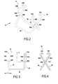
- the refractory structure shown on the figure 1 comprises anchoring bricks 10 which support between them a filling of refractory material 12, secured to the anchoring bricks by any known means.
- the whole of this structure is supported by support crosspieces 14, for example made up of metal beams with an I-section.
- these crosspieces constitute a superstructure part of an enclosure such as an oven, the structure of which refractory material constitutes the facing of the ceiling, so as to allow this chamber to withstand very high temperatures.
- Each of the anchoring bricks 10 is supported relative to a cross member 14 by a fastening device 16 according to the invention.
- Such a device is represented on the Figures 2 to 4 . It can be seen that it comprises two fittings, respectively 20 and 30. Each of these fittings comprises a retaining part, respectively 22 and 32, and hooking parts, respectively 23A and 23B for the fitting 20, and 33A and 33B for the fitting 30.
- connecting arms extend between the retaining part and the attachment parts. These arms are designated by the references 24A and 24B for the fitting 20, and by the references 34A and 34B for the fitting 30.
- each fitting has a U-shape, the retaining portion 22 or 32 forming the base of the U, while the connecting arms 24A, 24B or 34A, 34B form the branches of the U.
- the attachment parts are as to them located at the free ends of these branches.
- the retaining portions of the fittings serve to cooperate with a relief relief 10A of an anchoring brick.
- this relief relief has in this case the shape of a shoulder 10A under which engages the retaining part of a fitting.
- the hooking parts of the brackets cling to a hooking surface of the support 14, this surface being constituted for example by the lower bar 14A of the I formed by the section of the support beam 14.
- the two fittings of the attachment device are interconnected by being articulated with respect to each other.
- the hooking parts of the two fittings, located substantially vis-à-vis, and their respective retaining portions, also located substantially vis-à-vis can be moved closer to or away from each other.
- the connection between the fittings is achieved by their respective connecting arms, which cooperate with each other.
- the connecting arms 34A and 34B of Figure 30 are held between the connecting arms 24A and 24B of the fitting 20.
- the fitting 30, called the internal fitting is held by the internal face of the connecting arms of the fitting 20, said external fitting, being wedged longitudinally, in the direction of the double arrow I indicated on the figure 3 , compared to the latter.
- connecting arms The articulated cooperation between the connecting arms is in this case carried out without welding and without additional element. Indeed, as seen in the figures, these connecting arms have corrugations, by which they cooperate with each other.
- the connecting arms 24A and 24B of the external fitting 20 have outward corrugations 25A and 25B, respectively.
- the connecting arms 34A and 34B of the internal fitting 30 have inward corrugations 35A and 35B, respectively.
- the corrugations are located in the median regions of the connecting arms.
- the fittings are symmetrical with respect to a median plane P which is perpendicular to the longitudinal direction embodied by the double arrow I of the retaining part of the fitting.
- the linking arms 34A and 34B of the internal fitting 30 are inserted between the connecting arms 24A and 24B of the external fitting 20, until the corrugations 35A and 35B of the arms of the fitting 30 come be located in the corrugations 25A and 25B of the arms of the external fitting 20.
- the corrugations cooperate with each other by their respective recesses C.
- the depth of the undulations is of the same order of magnitude as the thickness e of a connecting arm.
- the depth d of the undulations of the connecting arms 34A and 34B of the internal fitting 30 is of the order of 1 to 2 times, in particular of the order of 1.5 times the thickness e, while the depth d of the undulations of the connecting arms of the external fitting 30 is of the order of 1 2 times, in particular of the order of 1 times the thickness e.
- the lengths L of the retaining portions 22 and 32 of the fittings are substantially equal, and slightly greater than the length L 'of the shoulders 10A of the anchoring bricks.
- each of the fittings is made in a folded wire.
- a metal alloy capable of withstanding high temperatures such as a so-called “refractory” alloy, will preferably be chosen.
- the connecting arms thus have a relative elasticity allowing the two connecting arms of the same fitting to move towards or slightly apart elastically from each other parallel to the longitudinal direction I of its retaining portion.
- the connecting arms 34A and 34B of the internal fitting 30 may be slightly brought closer elastically to one another so as to pass between the connecting arms 24A and 24B of the external fitting 20, until the corrugations 35A and 35B are received in the recesses of the corrugations 25A and 25B, respectively.
- the assembly between the two fittings is therefore extremely simple, and can therefore be performed without tools or additional parts.
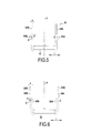
- the hooking parts of the brackets comprise hooks, respectively 23A and 23B for the fitting 20, and 33A and 33B for the fitting 30.
- the free ends of the connecting arms are simply bent on such so that, when the fittings are assembled, the free ends of their respective connecting arms are directed towards each other.
- the fittings are then manipulated in such a way that their respective retaining portions and their respective hooking parts are hooked together as shown in FIG. Figure 7A .
- the fittings tend to keep this position under the effect of the weight of the anchoring brick 10, the retaining portions 22 and 32 then being perfectly wedged in the corners 10C formed at the junction between the shoulders 10A and the rods of the anchoring bricks 10. If, under the effect of a rise in temperature, the anchoring bricks tend to slightly expand, this causes a slight spacing retaining portions 22 and 32, without impairing the quality of the attachment. When the anchor brick retracts again as a result of a drop in temperature, the articulation between the two fittings of the attachment device allows them to return to their original position, thus maintaining a perfect attachment.
Landscapes
- Engineering & Computer Science (AREA)
- Mechanical Engineering (AREA)
- General Engineering & Computer Science (AREA)
- Furnace Housings, Linings, Walls, And Ceilings (AREA)
Applications Claiming Priority (1)
| Application Number | Priority Date | Filing Date | Title |
|---|---|---|---|
| FR1055558A FR2962527A1 (fr) | 2010-07-08 | 2010-07-08 | Dispositif d'accrochage de briques d'ancrage pour refractaires |
Publications (2)
| Publication Number | Publication Date |
|---|---|
| EP2405221A2 true EP2405221A2 (de) | 2012-01-11 |
| EP2405221A3 EP2405221A3 (de) | 2014-03-05 |
Family
ID=43607804
Family Applications (1)
| Application Number | Title | Priority Date | Filing Date |
|---|---|---|---|
| EP11173196.4A Withdrawn EP2405221A3 (de) | 2010-07-08 | 2011-07-08 | Vorrichtung zum Anbringen von Verankerungsziegeln für Schamottsteine |
Country Status (2)
| Country | Link |
|---|---|
| EP (1) | EP2405221A3 (de) |
| FR (1) | FR2962527A1 (de) |
Citations (3)
| Publication number | Priority date | Publication date | Assignee | Title |
|---|---|---|---|---|
| US2657651A (en) | 1950-12-20 | 1953-11-03 | Babcock & Wilcox Co | Hanger construction for anchor tiles of refractory arches |
| FR1471908A (fr) | 1966-03-23 | 1967-03-03 | John G Stein & Company Ltd | Support pour éléments des voûtes suspendues de fours, et applications analogues |
| FR2193472A5 (de) | 1972-07-13 | 1974-02-15 | Skoda Np |
-
2010
- 2010-07-08 FR FR1055558A patent/FR2962527A1/fr not_active Withdrawn
-
2011
- 2011-07-08 EP EP11173196.4A patent/EP2405221A3/de not_active Withdrawn
Patent Citations (3)
| Publication number | Priority date | Publication date | Assignee | Title |
|---|---|---|---|---|
| US2657651A (en) | 1950-12-20 | 1953-11-03 | Babcock & Wilcox Co | Hanger construction for anchor tiles of refractory arches |
| FR1471908A (fr) | 1966-03-23 | 1967-03-03 | John G Stein & Company Ltd | Support pour éléments des voûtes suspendues de fours, et applications analogues |
| FR2193472A5 (de) | 1972-07-13 | 1974-02-15 | Skoda Np |
Also Published As
| Publication number | Publication date |
|---|---|
| FR2962527A1 (fr) | 2012-01-13 |
| EP2405221A3 (de) | 2014-03-05 |
Similar Documents
| Publication | Publication Date | Title |
|---|---|---|
| FR2929459A1 (fr) | Dispositif de fixation d'un chemin de cables en fils sur une tige filetee | |
| FR3009350A1 (fr) | Pince de fixation de materiau de couverture | |
| FR2982651A3 (fr) | Pince expansible avec tetes de machoire entrecroisees | |
| FR3018960A1 (fr) | Element d'accouplement pour troncons de chemin de cables en treillis metallique, et troncon de chemin de cables en treillis metallique | |
| EP2456931B1 (de) | Trennwand umfassend eine leiste mit Doppelverriegelung | |
| EP0300845A1 (de) | Vorrichtung für schwingungsneutralisierendes Festsetzen von Teilen einer Einrichtung und insbesondere schwingungsneutralisierende Stangen für Rotoren eines Dampferzeugers | |
| CA2296981C (fr) | Pince a cheveux a dents appariees | |
| EP2405221A2 (de) | Vorrichtung zum Anbringen von Verankerungsziegeln für Schamottsteine | |
| WO1991011650A1 (fr) | Dispositif de verrouillage de deux tubes coaxiaux | |
| FR2944302A1 (fr) | Element assurant la liaison d'armatures metalliques ou de treillis soudes destines a etre noyes dans du beton | |
| EP2107656A1 (de) | Befestigungsvorrichtung zum Aufhängen einer Gitterkabelbahn an einer Gewindestange | |
| FR2720874A1 (fr) | Pièce de suspension pour canalisation électrique. | |
| EP0325642B1 (de) | Punktbefestigungsvorrichtung von elementen mit einem rand, insbesondere von platten auf einer tragkonstruktion | |
| FR2584913A1 (fr) | Poignee de casserole demontable | |
| FR2905039A1 (fr) | Support pour fixer des cables electriques sur une structure | |
| FR2991518A3 (fr) | Support, destine a guider des cables dans des faux plafonds, dans des planchers techniques et dans des installations d'accessibilite reduite | |
| EP3816458B1 (de) | Klammer zum halten von zwei flachen elementen | |
| FR2610489A1 (fr) | Bracelet articule | |
| FR3004295A1 (fr) | Dispositif d'assemblage rapide de chemins de cables | |
| EP4283806A2 (de) | Verbindungselement für kabelrinnenabschnitte aus drahtgitter | |
| FR2812774A1 (fr) | Element permettant de former un chemin de cables | |
| FR2998314A1 (fr) | Dispositif de maintien des fers de renfort dans une structure de banchage d'une paroi | |
| FR3084899A1 (fr) | Accessoire de fixation d'un panneau de grillage a un poteau de cloture comportant une piece de blocage et une piece de serrage | |
| FR2792975A1 (fr) | Collier articule | |
| FR3053062A1 (fr) | Predalle a panier coulissant et panier correspondant |
Legal Events
| Date | Code | Title | Description |
|---|---|---|---|
| AK | Designated contracting states |
Kind code of ref document: A2 Designated state(s): AL AT BE BG CH CY CZ DE DK EE ES FI FR GB GR HR HU IE IS IT LI LT LU LV MC MK MT NL NO PL PT RO RS SE SI SK SM TR |
|
| AX | Request for extension of the european patent |
Extension state: BA ME |
|
| PUAI | Public reference made under article 153(3) epc to a published international application that has entered the european phase |
Free format text: ORIGINAL CODE: 0009012 |
|
| PUAL | Search report despatched |
Free format text: ORIGINAL CODE: 0009013 |
|
| AK | Designated contracting states |
Kind code of ref document: A3 Designated state(s): AL AT BE BG CH CY CZ DE DK EE ES FI FR GB GR HR HU IE IS IT LI LT LU LV MC MK MT NL NO PL PT RO RS SE SI SK SM TR |
|
| AX | Request for extension of the european patent |
Extension state: BA ME |
|
| RIC1 | Information provided on ipc code assigned before grant |
Ipc: F27D 1/14 20060101AFI20140128BHEP Ipc: F27B 3/12 20060101ALI20140128BHEP |
|
| STAA | Information on the status of an ep patent application or granted ep patent |
Free format text: STATUS: THE APPLICATION IS DEEMED TO BE WITHDRAWN |
|
| 18D | Application deemed to be withdrawn |
Effective date: 20140906 |