EP2405245A2 - Selbstkalibrierungsvorgang für optische Polarimeter - Google Patents
Selbstkalibrierungsvorgang für optische Polarimeter Download PDFInfo
- Publication number
- EP2405245A2 EP2405245A2 EP11173305A EP11173305A EP2405245A2 EP 2405245 A2 EP2405245 A2 EP 2405245A2 EP 11173305 A EP11173305 A EP 11173305A EP 11173305 A EP11173305 A EP 11173305A EP 2405245 A2 EP2405245 A2 EP 2405245A2
- Authority
- EP
- European Patent Office
- Prior art keywords
- calibration matrix
- optical
- polarimeter
- signal
- calibration
- Prior art date
- Legal status (The legal status is an assumption and is not a legal conclusion. Google has not performed a legal analysis and makes no representation as to the accuracy of the status listed.)
- Withdrawn
Links
- 238000000034 method Methods 0.000 title claims abstract description 83
- 230000003287 optical effect Effects 0.000 title claims abstract description 46
- 239000011159 matrix material Substances 0.000 claims abstract description 135
- 230000010287 polarization Effects 0.000 claims abstract description 80
- 239000013307 optical fiber Substances 0.000 claims description 6
- 230000001902 propagating effect Effects 0.000 claims description 5
- 230000004044 response Effects 0.000 claims description 5
- 238000005259 measurement Methods 0.000 abstract description 27
- 238000010561 standard procedure Methods 0.000 abstract description 23
- 239000013598 vector Substances 0.000 description 27
- 239000000835 fiber Substances 0.000 description 21
- 230000008569 process Effects 0.000 description 16
- 238000005457 optimization Methods 0.000 description 12
- 230000008033 biological extinction Effects 0.000 description 5
- 230000001419 dependent effect Effects 0.000 description 5
- 230000008859 change Effects 0.000 description 4
- 230000009466 transformation Effects 0.000 description 4
- 239000004983 Polymer Dispersed Liquid Crystal Substances 0.000 description 3
- 230000008901 benefit Effects 0.000 description 3
- 238000013461 design Methods 0.000 description 3
- 238000000844 transformation Methods 0.000 description 3
- 230000000694 effects Effects 0.000 description 2
- 238000009434 installation Methods 0.000 description 2
- 238000012546 transfer Methods 0.000 description 2
- 238000004364 calculation method Methods 0.000 description 1
- 230000001427 coherent effect Effects 0.000 description 1
- 238000004891 communication Methods 0.000 description 1
- 238000007796 conventional method Methods 0.000 description 1
- 238000012937 correction Methods 0.000 description 1
- 230000007423 decrease Effects 0.000 description 1
- 238000009795 derivation Methods 0.000 description 1
- 238000011161 development Methods 0.000 description 1
- 238000001914 filtration Methods 0.000 description 1
- 239000003550 marker Substances 0.000 description 1
- 238000012986 modification Methods 0.000 description 1
- 230000004048 modification Effects 0.000 description 1
- 230000002269 spontaneous effect Effects 0.000 description 1
- 238000012360 testing method Methods 0.000 description 1
Images



Classifications
-
- G—PHYSICS
- G01—MEASURING; TESTING
- G01J—MEASUREMENT OF INTENSITY, VELOCITY, SPECTRAL CONTENT, POLARISATION, PHASE OR PULSE CHARACTERISTICS OF INFRARED, VISIBLE OR ULTRAVIOLET LIGHT; COLORIMETRY; RADIATION PYROMETRY
- G01J4/00—Measuring polarisation of light
-
- G—PHYSICS
- G01—MEASURING; TESTING
- G01J—MEASUREMENT OF INTENSITY, VELOCITY, SPECTRAL CONTENT, POLARISATION, PHASE OR PULSE CHARACTERISTICS OF INFRARED, VISIBLE OR ULTRAVIOLET LIGHT; COLORIMETRY; RADIATION PYROMETRY
- G01J4/00—Measuring polarisation of light
- G01J4/04—Polarimeters using electric detection means
Definitions
- the present invention relates to a technique for calibrating an optical polarimeter and, more particularly, to a self-calibration procedure that does not rely on the use of an external polarization "standard” and can be used “in place” to calibrate a polarimeter during installation and/or operation in the field.
- Polarimeters measure the state of polarization of an input optical signal. Measurement of light polarization and its variation in time is important for many photonic applications, including telecommunications and fiber sensors. Widespread use of polarimeters has been limited, however, since they are typically made of bulk optic components, have an electrical bandwidth of less than 1MHz and require recalibration to operate over large wavelength ranges. Moreover, polarimeters are required to be calibrated and in most cases an external, reference polarimeter is required.
- the polarization transfer characteristics of an optical fiber device are important in the design of coherent lightwave communication systems.
- the transfer properties of fiber-based optic devices such as isolators, couplers, amplifiers and the like depend on the polarization state in the fiber itself.
- SOP state of polarization
- a conventional method for measuring the SOP of a light beam includes aligning a waveplate and a linear polarizer in the optical path of the beam.
- the waveplate is rotatable about the optical axis and is typically a quarter-wave plate.
- An optical sensor such as a photodetector, is positioned to measure the intensity of light transmitted by the waveplate and polarizer.
- the waveplate is sequentially rotated to a minimum of four angular positions about the optical axis relative to the linear polarizer, and the transmitted light intensity is measured at each position by the photodetector.
- a disadvantage of this method is the mechanical movement of the waveplate and the resulting slow speed of the measurement. Additionally, since every optical element must be aligned in free space, miniaturization of the device is not possible.
- S 0 is the total power
- S 1 is the linearly-polarized horizontal component minus the linearly-polarized vertical component
- S 2 is the linearly-polarized component at 45° minus the linearly-polarized component at -45°
- S 3 is the right-hand circularly polarized component minus the left-hand circularly polarized component.
- the present invention relates to a technique for calibrating an optical polarimeter and, more particularly, to a self-calibration procedure that does not rely on the use of an external polarization "standard” and can be used to calibrate a polarimeter during installation and/or operation in the field without having to remove the polarimeter from its current location to perform the calibration.
- the self-calibration technique is not limited to any specific type of polarimeter.
- a fit of the elements of a calibration matrix C to a set of measured detector values corresponding to a given input set of SOPs, which may or may not be known, is performed.
- the only constraint for this self-calibration procedure is that the source is a polarized light source (laser) with a degree of polarization (DOP) close to 100%.
- the data for self-calibration is then taken, for example, by moving a polarization controller several times to allow for the launch of signals with random and unknown SOPs and recording the detector output values (D 0 , ..., D 3 ) for each state of polarization. These values are then used, in one embodiment, to create an "approximate" (initial) calibration matrix.
- an initial matrix is derived from the measured detector output values.
- an estimated calibration matrix is used as the initial calibration matrix.
- One specific guess is based upon the presumption of a tetrahedral polarimeter configuration as defined below; alternatively, a random collection of values may be used as the initial calibration matrix.
- the total signal power may also be recorded for each of the several random and unknown SOPs. In this case, the measured power will be used in addition to the measured detector values to obtain the calibration.
- the first row of this initial calibration matrix is adjusted to produce the best fit of the measured total signal power values, preferably using a least squares fit.
- the launched signal power is constant during the calibration process (in that case, the power does not need to be measured for each of the several random and unknown SOPs).
- the first row of the initial calibration matrix is then fit to a constant power value for each of the several random and unknown launched input SOPs. It is to be noted that utilization of total signal power is an alternative only in the sense that if the power is fixed, the first row of the calibration matrix can be fit to a constant power. For this embodiment, either measured power or assumed constant power is required.
- one constraint includes maintaining a known angle (or angles) in the Stokes space among two or more SOPs of the different launched signals.
- the arrangement of the detectors along the polarimeter may be constrained. These constraints include, but are not limited to, creating fixed angles of projection states (as defined below), defining fixed extinctions for the detectors, or using more than four detectors (i.e., creating an over-determined polarimeter).
- a polarimeter formed in accordance with the present invention will provide a relatively broad calibration bandwidth if the properties of the detectors are "matched".
- the matching is generally in terms of characteristics such as responsivity and polarization optics (e.g., waveplates, birefringent fiber, polarizers and the like) and is preferably designed to be matched over a range of optical wavelengths, or electrical frequency, or operating temperature, etc.
- FIG. 1 is a schematic of an all-fiber polarimeter that may be characterized using the self-calibration technique of the present invention
- FIG. 2 contains plots of both DOP and grating scatter power as a function of wavelength for the arrangement of FIG. 1 ;
- FIG. 3 is a plot of the normalized frequency response of a set of four matched detectors used in the arrangement of FIG. 1 ;
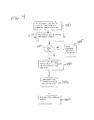
- FIG. 4 is a high level flow chart illustrating the self-calibration process of one embodiment of the present invention.
- FIG. 5 illustrates a polarimeter of FIG. 1 , when used in combination with a polarized laser source and polarization controller to perform the self-calibration technique of the present invention
- FIG. 6 is a variation of the arrangement of FIG. 4 , in this case including a power monitor to measure the input power of each applied optical signal at the entrance of the polarimeter;
- FIG. 7 is alternative embodiment of the present invention, utilizing a linear polarizer at the input of the polarimeter to create a known relationship (i.e., pair of orthogonal inputs) between at least two of the input optical signals; and
- FIG. 8 is a plot illustrating the standard deviation (and maximum) of the DOP as a function of the number of points involved in the calibration procedure.
- a polarimeter measures the four Stokes parameters defining the state of polarization of an incoming signal.
- a Stokes polarimeter is generally comprised of, at the least, polarization-sensitive optics, such as waveplates and polarizers, followed by a set of at least four detectors. The detectors are thus configured to measure the projection of the incoming light onto different Stokes vectors, establishing a linear relationship between the detector values and the Stokes vectors. Reference to the detectors in the following discussion will be understood to include polarization sensitive optics that precede the detectors in the optical path. The determination of this relationship is referred to as the calibration procedure and results in the creation of a calibration matrix C, relating N detector measurements to the four Stokes parameters (presented as a 4xN matrix).
- the generic procedure of the present invention performs a fit of the calibration matrix parameters to measured data. The data for such a procedure is obtained by launching light with different (and perhaps unknown) polarization states into the polarimeter and recording the detector voltages in each case
- constraints include one or more of the following: (1) degree of polarization (DOP) of approximately 100% for all launched signals; (2) constant power for all launched signals; (3) fixed, known orientations among the Stokes vectors of the launched signals; (4) two or more detectors projecting onto Stokes vectors with known orientations that are then not adjusted during the process. It is known that for the constraints defined in (3) or (4), two detectors measure projections of the launched signals onto linear polarizations separated by a spatial angle of ⁇ .
- DOP degree of polarization
- This spatial angular constraint is identical to a constraint on the angle between the Stokes vectors for the two linear polarizations.
- each detector measures a projection onto a given Stokes vector, where elements S 1 , S 2 and S 3 of these two vectors form two three-dimensional vectors that exhibit an angle of 2 ⁇ with respect to each other; or (5) power is measured for each incoming signal and used during the fitting routine to create the calibration matrix.
- constraints are considered to be exemplary; others may be utilized to create a unique solution for the calibration matrix.
- Polarimeter 10 as illustrated in FIG. 1 is used in the following discussion to illustrate the self-calibration technique of the present invention, according to an embodiment of the present invention. However, it is to be understood that the technique is not limited to use with only this arrangement, but finds use with virtually any polarimeter design. Reviewing the elements of polarimeter 10, it is seen to comprise an optical fiber 12 within which a set of four separate gratings has been formed (i.e., "written"). These four gratings are utilized to assist in determining the four Stokes parameters from the four measured detector values.
- an input optical signal I may be constrained (alternatively, and as discussed below, the detectors themselves may be disposed in a constrained configuration).
- a first grating 14 is shown as being an "on-axis" grating, that is, it scatters light in the direction of one of the two birefringent axes of the fiber and thus measures the Stokes projection of the light onto one of the two Stokes vectors defining the birefringent axes of the fiber, and thereafter directs a portion of the signal 1 into a first photodetector 16, creating a first detector electrical output signal D 0 .
- the remaining portion of optical signal 1 continues to propagate along optical fiber 12 and next encounters a second grating 18 (this oriented off-axis by, for example, 53°) which directs a second portion of signal I into a second photodetector 20, creating signal D 1 .
- a third grating 22 (oriented another 53° off-axis relative to grating 18) directing a portion of the optical signal into a third photodetector 24 (creating signal D 2 ), and a final grating 26 (oriented off-axis with respect to grating 22) and photodetector 28 used to create the fourth detector output signal D 3 .
- the selection of 53° is a design choice, yielding an optimal orientation of the projection states.
- other grating orientations may be used and are considered to fall within the scope of the present invention.
- FIG 2 contains plots of both the DOP and grating scatter power as a function of wavelength for a set of four matched detectors, illustrating a calibration bandwidth of approximately 33 nm. The resultant RF bandwidth is also increased over previous conventional polarimeters, as shown in FIG.
- FIG. 3 which contains the plots of the normalized frequency response (shown as exceeding 500 MHz) for a set of four matched detectors in the polarimeter of FIG. 1 .
- the RF responses are matched up to the cutoff frequency, providing improved accuracy for measurements of high speed polarization changes up to the cutoff frequency.
- these four detectors 16, 20, 24 and 28 require a 4x4 calibration matrix C to relate their respective voltage output signals (D 0 , D 1 , D 2 , D 3 ) to the four Stokes parameters that define the SOP of a propagating optical signal 1.
- a "four point" calibration procedure can be used to create this matrix, where four known and non-degenerate states of polarization are launched into the polarimeter and the detector values recorded.
- a simple matrix inversion then yields the calibration matrix. While this procedure is very efficient, it requires the generation of accurate reference measurements of the SOPs, which is often not practical.
- Embodiments of the present invention provide self-calibration procedures that do not require the use of any "reference signals”, relying instead on measured data from the polarimeter itself and analyze the data with respect to one or more constraints, as discussed below.
- the procedure involves a four-step process: (1) launching at least four signals into an optical polarimeter and recording the measured detector values, as well as the total launched power of each signal; (2) creating an approximate calibration matrix; (3) adjusting the first row of the approximate calibration matrix to fit the measured total power values for each launched signal (inasmuch as the first row of the matrix is associated with total power, it is always this first row that is adjusted as the process is employed); and (4) adjusting the remaining elements of the calibration matrix to satisfy a predetermined constraint.
- the second step may use a set of initially measured detector values, or an "ideal guess" of values.
- the third step in the procedure can use measured powers or, if the power was known to be constant, can use constant power values.
- DOP polarization dependent loss
- the self-calibration data is taken by first moving the polarization controller to allow for the launch of several (possibly random) and possibly unknown SOPs and then recording the detector values for each launch condition. Referring to FIG. 4 , this is shown by first launching a signal of a first SOP to the polarimeter (step 100), then measuring the electrical signals at the set ofN detectors (for example, four detectors) disposed along the polarimeter (step 110). In one embodiment, the launched power is also measured for this current SOP. A check is then made (step 120) to determine if a sufficient number of SOPs have been transmitted through the polarimeter for a sufficiently accurate calibration (at least four such measurements are required, more are desirable). If the answer is "no", the polarization controller adjusts the SOP to a different value (step 125) and the measurement process of step 110 is repeated.
- step 130 an initial, approximate calibration matrix is formed using the recorded detector values (or, alternatively, an ideal set of values).
- the first row of the calibration matrix is then adjusted, as defined in step 150, using an acceptable "best fit" methodology, such as a least squares fit. If the power was constant during the calibration procedure, then the first row is fit to a constant power. In this case, the absolute power in the detector would not be known since the only constraint would be that the power was constant. Alternatively, if the power was measured, the first row is fit to the measured values. It is to be noted that it is always the first row of the calibration matrix that is first adjusted, since the total power is a constraint on the fit of the remaining parameters in the calibration matrix.
- An acceptable first "guess” for these remaining elements is to scale them using the values in the first row. Accuracy can be increased, as will be discussed in detail below, by launching more SOPs or including more detectors in the polarimeter.
- the self-calibration procedure of the present invention does not require any a priori knowledge of the input SOPs, but only requires that the chosen constraint (e.g., DOP is essentially 100% for each SOP) is maintained.
- FIG. 5 illustrates an exemplary arrangement for accomplishing this procedure, including a laser source 30 for providing a relatively narrow linewidth polarized input optical signal 1, which than passes through a polarization controller 32 (an adjustable device) before passing through polarimeter 10.
- a polarization controller 32 an adjustable device
- the input SOP of signal 1 is controlled and the detector values used in the initial guess (if desired) and the calibration matrix are measured.
- polarization controller 32 is adjusted at least three separate times to create at least four different SOPs for the input signal launched into polarimeter 10.
- An initial guess for calibration matrix C is then created. It is to be noted that this initial guess may be refined by a rescaling at a later point in the process (see step 4, below), but the bulk of the computation may be done at this step. Two possible methods are outlined in the section, which begins with an analysis of the calibration matrix C that is useful in determining an initial guess, yielding a "model" calibration matrix. Following this, the initial guess for the calibration procedure is derived using the model calibration matrix.
- S CD
- D i P i ⁇ 0 ⁇ S 0 + P i ⁇ 1 ⁇ S 1 + P i ⁇ 2 ⁇ S 2 + P i ⁇ 3 ⁇ S 3
- g is the gain relating the optical power to the detector voltage
- ⁇ i (which is taken as positive) is related to the ratio of the minimum and maximum values that Di takes on as the input polarization state is varied
- p ⁇ i [p i1 p i2 p i3 ] is a unit Stokes vector on the
- the vector p ⁇ i is defined as the projection vector (or projection state) for detector i.
- each detector measures the projection of the input polarization state onto its projection vector.
- D i ⁇ min g i ⁇ S 0 1 - ⁇ i ⁇ DOP
- the parameter values defining P m can be extracted from measurements of the minimum and maximum values of the detector values as well as the values of the other detectors when another detector is at a min or max.
- D max 00 D max 01 D min 02 D min 03 D min 10 D min 11 D min 12 D min 13 D min 20 D min 21 D min 22 D min 23 D min 30 D min 31 D min 32 D min 33
- D max 00 is the maximum value of D 0
- D max 01 is the value of D 1 when D 0 is maximized, and vice versa.
- each column is formed by the four detector values measured when detector i is maximized or minimized.
- the minimum and maximum is taken over all of the random states and represents only an estimate of the actual minimum and maximum values.
- only an estimate of the calibration matrix can be achieved, using the model calibration matrix of equation (7).
- the parameters of the model inverse calibration matrix can then be derived from D max and D min (or their approximately values).
- S 0 is defined as 1, since the overall power does not affect the computation.
- the overall gain is arbitrary, so go may be set equal to one.
- equation (17) is not the only model inverse calibration matrix possible. However, it is the simplest form of this matrix, since orientation and overall scale factors have been removed. In fact, it will be valid for any four detector polarization sensitive device.
- the twelve parameters of the model calibration matrix may be used in one or more of the fitting routines described in association with the various embodiments of the present invention.
- the model calibration matrix of equation (17) can be used to produce a first guess of the calibration matrix C as used in the calibration procedure of the present invention.
- the first guess is obtained by using the minimum and maximum detector values as measured from the launch signals of the first step as outlined in equation (8) above.
- the launched polarization states are random, these values will not be the true maxima and minima, so the guess will be an estimate.
- the more random states that are launched the more accurate the first guess will be.
- Equation (17) may be technically accurate, in practice factors such as noise can easily make the twelve parameters deviate from the correct values. Equation (17) is obtained through the eight measurements of the minima and maxima of the detector values. If these are incorrect by small amounts, then the model calibration matrix can easily be off by a large amount. Therefore, another refinement is useful to ensure an accurate calibration. To perform this refinement, a standard reference for polarization measurement is required. One possibility is to launch certain polarization states such as linear and circular. This can be done with great accuracy; however, such a polarization state can degrade in the propagation path to the polarimeter as a result of intervening birefringence and polarization dependent loss (PDL).
- PDL birefringence and polarization dependent loss
- a more robust standard uses quantities that remain relatively invariant during propagation to the polarimeter.
- the DOP is first selected, and is controlled to be very close to one (i.e., 100% for all signals) by using narrow linewidth sources, high quality polarizers and filtering out all amplified spontaneous emission (ASE). Indeed, the DOP can remain very close to unity if the light source is narrowband and low noise, even when propagating through long lengths of fiber (e.g., > 100m) with polarization dependent delay and loss (or gain).
- a measure Q is defined that is to be minimized.
- the SOP values are not known. What is known are the measured detector values D 0 , D 1 , D 2 and D 3 .
- the simplest parameters to choose are the model calibration parameters as defined above in equation (17).
- the set of measurements D m is first used to provide an approximate first guess using the model calibration matrix C m .
- the first guess may be determined by an ideal matrix, such as that shown above in equation (18). In either case, this matrix is used as the first guess in the nonlinear least squares fit of equation (28). It is to be noted that the first guess can be quite inaccurate and still allow for convergence. It is to be noted that the model only depends on the relative gains, so the overall gain can be removed. After optimization, an appropriate scaling factor can be added into adjust the units of S 0 correctly.
- power measurements are used to address this issue.
- the power of each input signal is measured at some point along the path between the calibrating laser and the polarimeter, or at some point after or before either element. It is best to measure the power after the polarization controller that is generating the different polarization states.
- FIG. 6 illustrates this embodiment, where a power meter 34 is inserted to measure the power at the output of polarization controller 32. This power measurement point is then the reference point for the PDL.
- power meter 34 may also be placed beyond the output side of the polarimeter.
- the power measurement may be incorporated within the polarimeter itself.
- two of the gratings forming the polarimeter may be oriented at 90° with respect to each other such that the same scattering strength yields a detector voltage proportional to the power (S 0 ) in the fiber.
- Z and X are a matrix and vector, respectively, that depend on the input data and N data is the number of data points.
- the set of relations forming equations (32) can be solved by simply inverting Z. Note that this solution can also be extended to a polarimeter with more than four detectors.
- step 4" is described, that is, the process of fitting the remaining elements of the calibration matrix.
- the first row of calibration matrix C is now best fit to the power data, and a first guess for the remaining elements is obtained (derived from the initial guess obtained in step 2, as discussed above).
- this first guess can simply be the model calibration matrix shown in equation (17) using the detector data, or an ideal guess (such as equation (18) if the polarimeter is known to be close to tetrahedral).
- the initial guess matrix will have a first row that is different from the best fit value using the measured powers. This is due to the fact that the gains are not set correctly. Therefore, this first row must be replaced by the "best fit" first row.
- these may be scaled by a single factor to make them closer to the scaled values in the best fit first row. This can be accomplished by simply taking the average scale factor of the first row and dividing all other elements.
- C guess C 00 f C 01 f C 02 f C 03 f h ⁇ C 10 m h ⁇ C 11 m h ⁇ C 12 m h ⁇ C 13 m h ⁇ C 20 m h ⁇ C 21 m h ⁇ C 22 m h ⁇ C 23 m h ⁇ C 30 m h ⁇ C 31 m h ⁇ C 32 m h ⁇ C 33 m
- C f is the best fit first row from the measured powers
- C m is the model matrix derived from equation (17) (or the ideal model of equation (18))
- C m 1 ⁇ 0 ⁇ p ⁇ 0 1 ⁇ 1 ⁇ p ⁇ 1 1 ⁇ 2 ⁇ p ⁇ 2 1 ⁇ 3 ⁇ p ⁇ 3 - 1 ⁇ g 0 - 1 0 0 0 0 0 g 1 - 1 0 0 0 0 g 2 - 1 0 0 0 0 0 0 g 3 - 1 Since the gains g 1 are easily related to the first row of C, this form of C can be used to scale the first guess on a column-by-column basis.
- C scaled tetrahedral guess 1 4 ⁇ 1 1 1 1 3 - 1 - 1 - 1 0 2 ⁇ 2 - 2 - 2 0 0 6 - 6 ⁇ 4 ⁇ C 00 0 0 0 0 4 ⁇ C 01 0 0 0 0 4 ⁇ C 02 0 0 0 0 4 ⁇ C 03
- model matrix C m does not affect the first row of calibration matrix C. Only PDL transformations of the signals (i.e., polarization transformations that change the value of S 0 or the total power as function of the input polarization) will affect these values. Therefore, the orientation of P in equation (17) (or equation (18)) is not important. However, the PDL associated with model matrix C m is important and can skew the initial guess. It is also noted that the fit to the measured powers locks in a particular PDL value for calibration matrix C. Therefore, the PDL will not vary in the subsequent optimization of the other parameters.
- the optimization is then performed subject to the constraint that the first row of calibration matrix C is fixed.
- Q can also be normalized to the total power at each data point, S 0n .
- DOP the quantity to be minimized.
- calibration matrix C is varied to minimize a parameter that depends on how closely the constraints are met.
- R PDL C is a Mueller matrix with PDL along an arbitrary axis.
- R PDL is a Mueller matrix with PDL along an arbitrary axis.
- polarization states are launched that have some known relationship. The simplest relationship is pairwise orthogonality. That is, each pair of states is orthogonal. This can be achieved by passing the light through a linear polarizer 36 and then through a polarization controller 32 have a PDL fixed as a function of the control state, as shown in FIG. 7 . Note that the power can be different for the different launch states, and it does not need to be measured. There can also be PDL between the polarization converter and the polarimeter. The only requirement is that this PDL is not varying.
- the second term in equation (39) may also be used with the previously-described expression for Q as found in equations (35) and (28), where this term then imposes the orthogonality constraint in that fit as well.
- constraints may be imposed on the input calibration signals, it is also possible to impose constraints on the detectors and polarization optics in the polarimeter, for example, on the set of N detectors comprising the polarimeter.
- the Stokes parameters can be computed in more than one manner (as discussed above). For instance, if there are five detectors, then there are five groups of four detectors that can each be used to determine the polarization. The calibration procedure can then proceed by forcing these Stokes parameters to all be the same. The calibration procedure is then similar to that described above. First, an approximate solution is determined using the model calibration matrix. However, there are more detectors and thus more projection states. In this case, therefore, the initial estimate is derived from a model calibration matrix using more than four projection states, as defined in equation 16(b).
- the Stokes vector is computed using the five different sets of four detectors.
- C 4 inverse g 0 g 0 ⁇ ⁇ 0 0 0 g 1 - g 1 ⁇ ⁇ 1 0 0 g 2 g 2 ⁇ ⁇ 2 ⁇ c 02 g 2 ⁇ ⁇ 2 ⁇ s 02 0 g 3 g 3 ⁇ ⁇ 3 ⁇ c 03 g 3 ⁇ ⁇ 3 ⁇ s 03 cos ⁇ 3 g 3 ⁇ ⁇ 3 ⁇ s 03 sin ⁇ 3
- FIG. 8 is a plot illustrating the standard deviation (and maximum) of the DOP as a function of the number of points involved in the calibration. As shown, convergence to less than 1 % (for the maximum deviation) is very fast, requiring only 12 to 15 points. Convergence to an asymptotic value (approximately 0.02%) is somewhat slower, requiring about 30 random points.
- the entire calibration procedure is performed with a given number of launched signals and if a sufficiently good fit of C to the launched signal data is achieved, no further data points are used. On the other hand, if the fit is still not optimal, then an additional data point is generated.
- Calibration quality is determined by a given calibration metric.
- One calibration metric is the standard deviation of the DOP (computed using C and the detector values) computed for all launch signals in the calibration data (the "standard deviation", shown as 'stdev dop' in FIG. 8 ).
- Another possible metric is the maximum deviation of the DOP from 100% for all launched signals (shown as 'maxdev' in FIG. 8 ). In either case, the plots in FIG.
- the calibration metric decreases as the number of points used in the calibration increases.
- no further points are taken and the calibration is defined as complete.
- a given calibration metric may be required to be achieved for several iterations before defining the calibration process as being complete.
- a calibration Once a calibration has been achieved, it can be used without further modification. However, it is of interest for some applications to reference the calibration to a particular SOP or set of SOPs at some point away from the polarimeter. When there are multiple calibrations over a wavelength range, it is also important that these calibrations agree. In general, there are several types of referencing that can be done including, but not limited to: (1) canonical rotation, (2) rotation to a user-defined state, (3) alignment with respect to an internal axis/axes, (4) alignment of one wavelength calibration with respect to another, or (5) alignment with respect a fiber grating axis/axes. Each of these will be described in turn below.
- Canonical rotation refers to a particular orientation of the projection states defined in equation (7).
- the canonical rotation is a three-dimensional rotation on the Poincare sphere that rotates a calibration matrix C to the desired canonical orientation, where this orientation is the same as that defined in equation (17).
- the first detector measures linear polarization at 0 degrees and the second detector performs the measurement at another angle, but is still measuring purely linear polarization.
- the matrix P has three zeroes, as shown in equation (17).
- User-defined rotation is essentially the same as the canonical rotation, however in this case two measured SOPs are used instead of the projection states.
- the user may launch linear and circular polarization states.
- Calibration matrix C is then rotated so that the Stokes parameters produced by the polarimeter match the user inputs.
- Alignment with respect to an internal axis or axes can also be used.
- the internal axis might be the high birefringence axis of a high birefringence polarimeter.
- One way to perform alignment to an internal high birefringence axis is to launch light into this axis and then rotate the calibration so that the polarization is linear for the state that is aligned with respect to the axis.
- one of the detectors is already aligned with the high birefringence axis. In this case, the alignment can be done internally. If the detector is close the high birefringence axis, then the alignment accuracy can be improved through a high birefringence launch.
- Another possibility is to launch light of a single polarization and then vary the wavelength or temperature.
- the polarization will rotate around the local high birefringence axis as long as this high birefringence axis dominates the birefringence between the fiber polarimeter and the laser.
- the projection states will rotate around the local birefringence, so this can also be used to find the axis.
- wavelength insensitive orthogonality of two states This can be achieved if the two gratings are very close along the fiber. It is also aided if they have the same angle with respect to the high birefringence axis. In particular, if they are both close to the high birefringence axis, then it is advantageous for them to be separated by roughly half of a beat length. Even if they have some angle with respect to the high birefringence axis, if they are separated by a half beat length, they will remain orthogonal to first order as wavelength changes.
- a set of polarizations for one wavelength is launched and the same set is launched for another wavelength. After calibration at each wavelength, rotations are made on each calibration matrix so that the two sets of polarizations overlap.
Landscapes
- Physics & Mathematics (AREA)
- General Physics & Mathematics (AREA)
- Spectroscopy & Molecular Physics (AREA)
- Spectrometry And Color Measurement (AREA)
- Investigating Or Analysing Materials By Optical Means (AREA)
- Optical Modulation, Optical Deflection, Nonlinear Optics, Optical Demodulation, Optical Logic Elements (AREA)
- Testing Of Optical Devices Or Fibers (AREA)
Applications Claiming Priority (3)
| Application Number | Priority Date | Filing Date | Title |
|---|---|---|---|
| US36263310P | 2010-07-08 | 2010-07-08 | |
| US38067710P | 2010-09-07 | 2010-09-07 | |
| US13/177,116 US20120010842A1 (en) | 2010-07-08 | 2011-07-06 | Self-Calibration Procedure For Optical Polarimeters |
Publications (2)
| Publication Number | Publication Date |
|---|---|
| EP2405245A2 true EP2405245A2 (de) | 2012-01-11 |
| EP2405245A3 EP2405245A3 (de) | 2013-04-17 |
Family
ID=44562713
Family Applications (1)
| Application Number | Title | Priority Date | Filing Date |
|---|---|---|---|
| EP11173305.1A Withdrawn EP2405245A3 (de) | 2010-07-08 | 2011-07-08 | Selbstkalibrierungsvorgang für optische Polarimeter |
Country Status (3)
| Country | Link |
|---|---|
| US (1) | US20120010842A1 (de) |
| EP (1) | EP2405245A3 (de) |
| JP (1) | JP6068783B2 (de) |
Families Citing this family (5)
| Publication number | Priority date | Publication date | Assignee | Title |
|---|---|---|---|---|
| JP5834938B2 (ja) * | 2012-01-17 | 2015-12-24 | 株式会社リコー | 分光特性取得装置、画像評価装置、画像形成装置及び分光特性取得方法 |
| US9116036B2 (en) * | 2013-03-15 | 2015-08-25 | Ofs Fitel, Llc | Optical polarimeter |
| CN104180904A (zh) * | 2014-08-15 | 2014-12-03 | 中国科学院上海技术物理研究所 | 一种基于旋转偏振片的分时红外偏振探测系统定标方法 |
| CN116106203A (zh) * | 2023-02-28 | 2023-05-12 | 清华大学深圳国际研究生院 | 悬浮粒子偏振测量方法、装置及其全角度同步校准方法 |
| CN119268845B (zh) * | 2024-10-30 | 2026-03-27 | 中国科学院西安光学精密机械研究所 | 一种适用于高能激光偏振检测的斯托克斯参量校正方法 |
Citations (2)
| Publication number | Priority date | Publication date | Assignee | Title |
|---|---|---|---|---|
| US4681450A (en) | 1985-06-21 | 1987-07-21 | Research Corporation | Photodetector arrangement for measuring the state of polarization of light |
| US6917427B2 (en) | 2002-04-10 | 2005-07-12 | Thorlabs Gmbh | Highly accurate calibration of polarimeters |
Family Cites Families (9)
| Publication number | Priority date | Publication date | Assignee | Title |
|---|---|---|---|---|
| US5296913A (en) * | 1992-10-08 | 1994-03-22 | Hewlett-Packard Company | Polarimeter re-calibration method and apparatus |
| CA2380492A1 (en) * | 1999-07-27 | 2001-02-01 | Thomas E. Furtak | Parallel detecting, spectroscopic ellipsometers/polarimeters |
| US6211957B1 (en) * | 2000-03-03 | 2001-04-03 | Lucent Technologies, Inc. | In-line all-fiber polarimeter |
| JP3793420B2 (ja) * | 2000-03-08 | 2006-07-05 | ルーセント テクノロジーズ インコーポレーテッド | 光通信システム及びこのシステムに使用する偏光制御デバイス |
| US6816260B2 (en) * | 2001-05-17 | 2004-11-09 | Thorlabs Gmbh | Fiber polarimeter, the use thereof, as well as polarimetric method |
| WO2003021822A1 (en) * | 2001-08-31 | 2003-03-13 | Fujitsu Limited | Polarization mode dispersion compensator based on degree of polarization |
| US7079246B2 (en) * | 2003-04-15 | 2006-07-18 | Lucent Technologies Inc. | Method and apparatus for measuring polarization |
| JP4302658B2 (ja) * | 2005-03-31 | 2009-07-29 | 古河電気工業株式会社 | ストークスパラメータ補正方法およびストークスパラメータ測定装置 |
| JP4875688B2 (ja) * | 2008-12-01 | 2012-02-15 | 古河電気工業株式会社 | ストークスパラメータ補正方法およびストークスパラメータ測定装置 |
-
2011
- 2011-07-06 US US13/177,116 patent/US20120010842A1/en not_active Abandoned
- 2011-07-08 JP JP2011151357A patent/JP6068783B2/ja not_active Expired - Fee Related
- 2011-07-08 EP EP11173305.1A patent/EP2405245A3/de not_active Withdrawn
Patent Citations (2)
| Publication number | Priority date | Publication date | Assignee | Title |
|---|---|---|---|---|
| US4681450A (en) | 1985-06-21 | 1987-07-21 | Research Corporation | Photodetector arrangement for measuring the state of polarization of light |
| US6917427B2 (en) | 2002-04-10 | 2005-07-12 | Thorlabs Gmbh | Highly accurate calibration of polarimeters |
Non-Patent Citations (1)
| Title |
|---|
| R.M.A. AZZAM: "In-line Light-saving Photopolarimeter and its Fiber-optic Analog", OPTICS LETTERS, vol. 12, 1987, pages 558 - 60, XP001031907 |
Also Published As
| Publication number | Publication date |
|---|---|
| EP2405245A3 (de) | 2013-04-17 |
| JP2012018165A (ja) | 2012-01-26 |
| JP6068783B2 (ja) | 2017-01-25 |
| US20120010842A1 (en) | 2012-01-12 |
Similar Documents
| Publication | Publication Date | Title |
|---|---|---|
| US7436569B2 (en) | Polarization measurement and self-calibration based on multiple tunable optical polarization rotators | |
| US6859268B2 (en) | Compensating polarization mode dispersion in fiber optic transmission systems | |
| EP0536538B1 (de) | Verfahren zur Messung der Polarisationsempfindlichkeit optischer Vorrichtungen | |
| US7027198B2 (en) | Generation and analysis of state of polarization using tunable optical polarization rotators | |
| US6204924B1 (en) | Method and apparatus for measuring polarization mode dispersion of optical devices | |
| US20060115199A1 (en) | Measurements of polarization-dependent loss (PDL) and degree of polarization (DOP) using optical polarization controllers | |
| US20060023987A1 (en) | Optical instrument and measurements using multiple tunable optical polarization rotators | |
| EP2405245A2 (de) | Selbstkalibrierungsvorgang für optische Polarimeter | |
| CN102519713A (zh) | 基于最小二乘优化的全物理偏振参数的测量装置和方法 | |
| JP4424583B2 (ja) | 偏光計の校正方法 | |
| US6836327B1 (en) | In-line optical polarimeter based on integration of free-space optical elements | |
| US9448116B2 (en) | Free space single-mode fibers and fiber components for fiber sensor applications | |
| US9025146B2 (en) | In-line arrangement for measuring polarization extinction ratio | |
| EP1421717B1 (de) | Polarisationsmodendispersion-kompensator auf basis des polarisationsgrades | |
| US11002632B2 (en) | Measuring polarization extinction ratio (PER) using a reference master test jumper (MTJ) | |
| Kyselak et al. | Optical birefringence fiber temperature sensors in the visible spectrum of light | |
| Shatalin et al. | Location of high PMD sections of installed system fiber | |
| JP5897056B2 (ja) | 光学偏光計 | |
| Mikhailov et al. | In-line high-speed all-fiber polarimeter with true real-time acquisition for sensor systems based on fast polarization rotation | |
| Mikhailov et al. | In-line, high speed fibre polarimeter with large calibration bandwidth and accurate reference-free calibration procedure | |
| JPH07243940A (ja) | 偏波依存損失測定方法および装置 | |
| Kim et al. | An evaluation of polarization-dependent loss-characterization methods | |
| Stevens | Polarisation extinction ratio-measurement requirements for optical communication systems. | |
| CA2229219A1 (en) | Method and apparatus for measuring polarization mode dispersion of optical devices | |
| Buchilko et al. | Analysis of the State of Polarization at the Output of an Imperfect Faraday Rotator Mirror |
Legal Events
| Date | Code | Title | Description |
|---|---|---|---|
| AK | Designated contracting states |
Kind code of ref document: A2 Designated state(s): AL AT BE BG CH CY CZ DE DK EE ES FI FR GB GR HR HU IE IS IT LI LT LU LV MC MK MT NL NO PL PT RO RS SE SI SK SM TR |
|
| AX | Request for extension of the european patent |
Extension state: BA ME |
|
| PUAI | Public reference made under article 153(3) epc to a published international application that has entered the european phase |
Free format text: ORIGINAL CODE: 0009012 |
|
| PUAL | Search report despatched |
Free format text: ORIGINAL CODE: 0009013 |
|
| AK | Designated contracting states |
Kind code of ref document: A3 Designated state(s): AL AT BE BG CH CY CZ DE DK EE ES FI FR GB GR HR HU IE IS IT LI LT LU LV MC MK MT NL NO PL PT RO RS SE SI SK SM TR |
|
| AX | Request for extension of the european patent |
Extension state: BA ME |
|
| RIC1 | Information provided on ipc code assigned before grant |
Ipc: G01J 4/00 20060101AFI20130308BHEP Ipc: G01J 4/04 20060101ALI20130308BHEP |
|
| 17P | Request for examination filed |
Effective date: 20131017 |
|
| RBV | Designated contracting states (corrected) |
Designated state(s): AL AT BE BG CH CY CZ DE DK EE ES FI FR GB GR HR HU IE IS IT LI LT LU LV MC MK MT NL NO PL PT RO RS SE SI SK SM TR |
|
| 17Q | First examination report despatched |
Effective date: 20180529 |
|
| STAA | Information on the status of an ep patent application or granted ep patent |
Free format text: STATUS: THE APPLICATION IS DEEMED TO BE WITHDRAWN |
|
| 18D | Application deemed to be withdrawn |
Effective date: 20181009 |