EP2405516B1 - Polymerelektrolyt-brennstoffzellendichtung - Google Patents
Polymerelektrolyt-brennstoffzellendichtung Download PDFInfo
- Publication number
- EP2405516B1 EP2405516B1 EP10748505.4A EP10748505A EP2405516B1 EP 2405516 B1 EP2405516 B1 EP 2405516B1 EP 10748505 A EP10748505 A EP 10748505A EP 2405516 B1 EP2405516 B1 EP 2405516B1
- Authority
- EP
- European Patent Office
- Prior art keywords
- shaped portion
- apex
- gasket
- sealing
- side bell
- Prior art date
- Legal status (The legal status is an assumption and is not a legal conclusion. Google has not performed a legal analysis and makes no representation as to the accuracy of the status listed.)
- Active
Links
Images





Classifications
-
- H—ELECTRICITY
- H01—ELECTRIC ELEMENTS
- H01M—PROCESSES OR MEANS, e.g. BATTERIES, FOR THE DIRECT CONVERSION OF CHEMICAL ENERGY INTO ELECTRICAL ENERGY
- H01M8/00—Fuel cells; Manufacture thereof
- H01M8/02—Details
- H01M8/0202—Collectors; Separators, e.g. bipolar separators; Interconnectors
- H01M8/0258—Collectors; Separators, e.g. bipolar separators; Interconnectors characterised by the configuration of channels, e.g. by the flow field of the reactant or coolant
- H01M8/0263—Collectors; Separators, e.g. bipolar separators; Interconnectors characterised by the configuration of channels, e.g. by the flow field of the reactant or coolant having meandering or serpentine paths
-
- H—ELECTRICITY
- H01—ELECTRIC ELEMENTS
- H01M—PROCESSES OR MEANS, e.g. BATTERIES, FOR THE DIRECT CONVERSION OF CHEMICAL ENERGY INTO ELECTRICAL ENERGY
- H01M8/00—Fuel cells; Manufacture thereof
- H01M8/02—Details
- H01M8/0202—Collectors; Separators, e.g. bipolar separators; Interconnectors
- H01M8/0267—Collectors; Separators, e.g. bipolar separators; Interconnectors having heating or cooling means, e.g. heaters or coolant flow channels
-
- H—ELECTRICITY
- H01—ELECTRIC ELEMENTS
- H01M—PROCESSES OR MEANS, e.g. BATTERIES, FOR THE DIRECT CONVERSION OF CHEMICAL ENERGY INTO ELECTRICAL ENERGY
- H01M8/00—Fuel cells; Manufacture thereof
- H01M8/02—Details
- H01M8/0271—Sealing or supporting means around electrodes, matrices or membranes
- H01M8/0273—Sealing or supporting means around electrodes, matrices or membranes with sealing or supporting means in the form of a frame
-
- H—ELECTRICITY
- H01—ELECTRIC ELEMENTS
- H01M—PROCESSES OR MEANS, e.g. BATTERIES, FOR THE DIRECT CONVERSION OF CHEMICAL ENERGY INTO ELECTRICAL ENERGY
- H01M8/00—Fuel cells; Manufacture thereof
- H01M8/02—Details
- H01M8/0271—Sealing or supporting means around electrodes, matrices or membranes
- H01M8/0276—Sealing means characterised by their form
-
- H—ELECTRICITY
- H01—ELECTRIC ELEMENTS
- H01M—PROCESSES OR MEANS, e.g. BATTERIES, FOR THE DIRECT CONVERSION OF CHEMICAL ENERGY INTO ELECTRICAL ENERGY
- H01M8/00—Fuel cells; Manufacture thereof
- H01M8/02—Details
- H01M8/0271—Sealing or supporting means around electrodes, matrices or membranes
- H01M8/0286—Processes for forming seals
-
- H—ELECTRICITY
- H01—ELECTRIC ELEMENTS
- H01M—PROCESSES OR MEANS, e.g. BATTERIES, FOR THE DIRECT CONVERSION OF CHEMICAL ENERGY INTO ELECTRICAL ENERGY
- H01M8/00—Fuel cells; Manufacture thereof
- H01M8/24—Grouping of fuel cells, e.g. stacking of fuel cells
- H01M8/241—Grouping of fuel cells, e.g. stacking of fuel cells with solid or matrix-supported electrolytes
- H01M8/242—Grouping of fuel cells, e.g. stacking of fuel cells with solid or matrix-supported electrolytes comprising framed electrodes or intermediary frame-like gaskets
-
- H—ELECTRICITY
- H01—ELECTRIC ELEMENTS
- H01M—PROCESSES OR MEANS, e.g. BATTERIES, FOR THE DIRECT CONVERSION OF CHEMICAL ENERGY INTO ELECTRICAL ENERGY
- H01M8/00—Fuel cells; Manufacture thereof
- H01M8/24—Grouping of fuel cells, e.g. stacking of fuel cells
- H01M8/2465—Details of groupings of fuel cells
- H01M8/2483—Details of groupings of fuel cells characterised by internal manifolds
-
- H—ELECTRICITY
- H01—ELECTRIC ELEMENTS
- H01M—PROCESSES OR MEANS, e.g. BATTERIES, FOR THE DIRECT CONVERSION OF CHEMICAL ENERGY INTO ELECTRICAL ENERGY
- H01M8/00—Fuel cells; Manufacture thereof
- H01M8/10—Fuel cells with solid electrolytes
- H01M2008/1095—Fuel cells with polymeric electrolytes
-
- H—ELECTRICITY
- H01—ELECTRIC ELEMENTS
- H01M—PROCESSES OR MEANS, e.g. BATTERIES, FOR THE DIRECT CONVERSION OF CHEMICAL ENERGY INTO ELECTRICAL ENERGY
- H01M8/00—Fuel cells; Manufacture thereof
- H01M8/02—Details
- H01M8/0271—Sealing or supporting means around electrodes, matrices or membranes
- H01M8/028—Sealing means characterised by their material
- H01M8/0284—Organic resins; Organic polymers
-
- H—ELECTRICITY
- H01—ELECTRIC ELEMENTS
- H01M—PROCESSES OR MEANS, e.g. BATTERIES, FOR THE DIRECT CONVERSION OF CHEMICAL ENERGY INTO ELECTRICAL ENERGY
- H01M8/00—Fuel cells; Manufacture thereof
- H01M8/24—Grouping of fuel cells, e.g. stacking of fuel cells
- H01M8/2465—Details of groupings of fuel cells
- H01M8/247—Arrangements for tightening a stack, for accommodation of a stack in a tank or for assembling different tanks
- H01M8/248—Means for compression of the fuel cell stacks
-
- Y—GENERAL TAGGING OF NEW TECHNOLOGICAL DEVELOPMENTS; GENERAL TAGGING OF CROSS-SECTIONAL TECHNOLOGIES SPANNING OVER SEVERAL SECTIONS OF THE IPC; TECHNICAL SUBJECTS COVERED BY FORMER USPC CROSS-REFERENCE ART COLLECTIONS [XRACs] AND DIGESTS
- Y02—TECHNOLOGIES OR APPLICATIONS FOR MITIGATION OR ADAPTATION AGAINST CLIMATE CHANGE
- Y02E—REDUCTION OF GREENHOUSE GAS [GHG] EMISSIONS, RELATED TO ENERGY GENERATION, TRANSMISSION OR DISTRIBUTION
- Y02E60/00—Enabling technologies; Technologies with a potential or indirect contribution to GHG emissions mitigation
- Y02E60/30—Hydrogen technology
- Y02E60/50—Fuel cells
Definitions
- the present invention relates to a fuel cell used for a portable power supply, an electric vehicle-use power supply, a household cogeneration system, or the like.
- the present invention relates to a gasket for a polymer electrolyte fuel cell using polyelectrolyte.
- a fuel cell using polyelectrolyte allows a hydrogen-containing fuel gas and an oxygen-containing oxidant gas, such as air, to electrochemically react with each other, such that electric power and heat are generated at the same time.
- the fuel cell is basically structured with a polymer electrolyte membrane that selectively transports hydrogen ions, and paired electrodes formed on both the surfaces of polymer electrolyte membrane, i.e., the anode and the cathode, respectively.
- These electrodes each have a catalyst layer whose principal component is carbon powder bearing platinum metal catalyst and which is formed on the front surface of the polymer electrolyte membrane, and a gas diffusion layer which has combined features of air permeability and electronic conductivity and which is disposed on the outer surface of the catalyst layer.
- Such an assembly made up of the polymer electrolyte membrane and the electrodes (including the gas diffusion layers) being integrally joined and assembled is referred to as an electrolyte membrane electrode assembly (hereinafter referred to as the "MEA").
- electrically conductive separators for mechanically clamping the MEA to fix the same, and for establishing electrical connection in series between the MEA and adjacent MEA, are disposed, respectively.
- gas flow channels for supplying corresponding electrodes with the fuel gas or a reactant gas such as the oxidant gas, and for carrying away the generated water or excess gas are formed.
- the gas flow channels can be provided separately from the separators, what is generally employed is to form grooves on the front surfaces of the separators to serve as the gas flow channels. It is to be noted that, such a structure body in which the MEA is clamped between the paired separators is referred to as the "unit cell module".
- Supply of the reactant gas to the gas flow channels formed between the separators and the MEA and discharge of the reactant gas and the generated water from the gas flow channels are each carried out in the followingmanner: throughholes called manifold holes are provided at the edge portion of at least one of the paired separators, to establish communication between the inlet/outlet port of each of the gas flow channels and each of the manifold holes, and the reactant gas is distributed to the gas flow channels from the manifold holes.
- gas sealing members or gaskets are disposed as sealing members between the paired separators, at the places where the electrodes are formed in the MEA, that is, so as to surround the external circumference of the power generation areas.
- the gas sealing members or the gaskets also seal the circumference of each of the manifold holes.
- a cooling portion for allowing the coolant to flow is provided every one to three cells.
- the general structure of a stacked battery (fuel cell stack) is as follows: theMEA, the separators, and the cooling portions are alternately stacked by ten to two hundred cells; thereafter, an end plate is disposed at each of the end portions of the whole cells with a current collector and an insulating plate interposed between the endplate and the endportion thereof, such that the whole cells are clamped between such paired end plates and fixed from both the ends through the use of fastening bolts (rods) or the like.
- the general method is to fasten with fastening bolts which are inserted into through holes formed at the edge portions of the separators; or to fasten up the entire stacked battery with a metal belt, having the end plates interposed therebetween.
- Patent Document 1 is a carbon member as one example, which has a gasket provided with two lips 200 in parallel to each other, to thereby secure the sealing performance without inviting an increase in the surface pressure, taking into consideration of a reduction in thickness of the sealing portion, an improvement in assemblability, prevention of misalignment, a reduction in surface pressure, and excellent evenness in surface pressure.
- Patent Document 2 proposes a gasket 201 having a two-stepped structure which is shown in Fig. 9 , as one example of a gasket capable of satisfying the requirement for a reduction in the reaction force, preventing the lip from collapsing, and maintaining the sealing performance even with slight unevenness or steps on the counter face.
- the gasket 201 is attached through integral molding to one of two members opposing to each other.
- a sealing lip 202 integrally molded to the gasket 201 to be brought into close contact with the other member is in a shape having a small collapsed volume for achieving a reduction in the reaction force.
- Patent Document 3 discloses a fuel cell-use gasket including a sealing portion having an internal seal formed with a lip having a substantially triangular cross section projecting toward both sides, and an external seal positioned externally to the internal seal and formed with a lip having substantially triangular cross section projecting toward both sides, in which the internal seal and the external seal are coupled with an annular coupling portion. With such a structure, it achieves an excellent sealing performance and a suppressed reaction force, and solves the problem of the gasket being collapsed.
- Patent Document 4 discloses a sealing portion provided with a sealing lip having a bidirectional sealing performance, in which a sealing lip possessing a unidirectional sealing performance is provided on one side or on both the sides of the sealing lip. Such a structure is capable of satisfying the requirement for a reduction in the reaction force, maintaining the sealing function even upon an occurrence of a collapsing phenomenon at the lip, and further, maintaining the sealing function even with slight unevenness or steps on the counter face.
- Patent Document 5 discloses paired interval restricting portions, each having a cross section of a rectangular shape or the like and disposed around the periphery of a rubber sheet, in which a lip line portion having a cross section of a bell-shape or a triangular shape is disposed between the paired interval restricting portions.
- the paired interval restricting portions is to control the dimension such that the desired behavior of compression deformation is attained by the lip line portion.
- Patent Document 6 discloses a flat seal structure with a bead-like sealing lip (also referred to as a bead) in which a rubber as a gasket body that is made of a rubber-like elastic material and that has a sealing lip portion is formed to have a triangular or bell-shaped cross section. Further, Patent Document 6 also discloses a gasket body on each of both the sides of an electrolyte membrane, the gasket body being provided with bead-like sealing lip portions two-pieces each. This makes it possible to prevent a reduction in the surface pressure peak value of the gasket body, even in a case where the bonding position of resin films on both the sides are somewhat displaced sideways.
- Patent Documents 1 to 7 fail to solve a plurality of issues, such as a reduction in the size and space of the stack, a reduction in fastening pressure, and maintenance of an ensured sealing performance.
- a low sealing performance is exhibited because the lips are too small for retaining a double-ensured sealing performance.
- Patent Document 2 when simply a double seal is employed, it invites an increase in the area required for the seal, which consequently invites an increase in both the stack volume and the fastening pressure.
- an object of the present invention is to resolve the issues described above, and to provide a polymer electrolyte fuel cell-use gasket which, in connection with a polymer electrolyte fuel cell, provides a double seal structure capable of surely securing the sealing performance, and which is at the same time capable of achieving the conflicting demands, i.e., a reduction in size of the stack and a reduction in the fastening force.
- the present invention is structured as follows.
- a polymer electrolyte fuel cell-use gasket provides a polymer electrolyte fuel cell-use gasket, included in a polymer electrolyte fuel cell comprising a fuel cell stack in which a stacked product assembled by being clamped by a fastening member via paired end plates respectively disposed at both ends of the stacked product, the stacked product being structured with a plurality of unit cell modules being stacked, each of the unit cell modules comprising: a membrane electrode assembly; a sealing member disposed at an external circumference of each of both front and back surfaces of the membrane electrode assembly; and paired separators sandwiching the membrane electrode assembly and the sealing member, characterized in that the sealing member is integrally molded with the external circumference portion of each of both the front and back surfaces of the membrane electrode assembly, as the sealing member, two rows of sealing lips each having a sealing performance are continuously provided in parallel to each other in an in-plane manner, at least an outer one of the two rows of sealing lips is integrally formed having a
- the polymer electrolyte fuel cell-use gasket according to the first aspect, wherein defining that the radius of curvature of the apex of the bottom side bell-shaped portion is R 1 , and that the radius of curvature of the apex of the top side bell-shaped portion is R 2 , a correlation between the radius of curvature R 1 and the radius of curvature R 2 satisfies R 1 ⁇ 0.5 ⁇ R 2 , and a height of a portion between the two rows of sealing lips is formed to be lower than a height at which the separator at each of both the front and back surfaces of the membrane electrode assembly fastens the two rows of sealing lips.
- a vertex angle of the bottom side bell-shapedportion and a vertex angle of the top side bell-shaped portion are each 18° or more, and a dimension in a thickness direction from a front surface of the external circumference of the membrane electrode assembly to the apex of the top side bell-shaped portion relative to an entire width being perpendicular to a thickness direction of the two rows of sealing lips and along a directionperpendicular to an extending direction of each of the two rows of sealing lips is 60% or less.
- the polymer electrolyte fuel cell-use gasket according to one of the first to third aspects, wherein a cross section nearby the apex of the top side bell-shaped portion and a cross section nearby the apex of the bottom side bell-shaped portion are both circular, the top side bell-shaped portion is a deformation facilitated portion, in which a portion of the apex of the top side bell-shaped portion elastically deforms greater than a portion of the apex of the bottom side bell-shaped portion does with being brought into contact with the separator when the fuel cell stack is assembled, and the bottom side bell-shaped portion is a seal area enlarging portion, in which, after the deformation facilitated portion elastically deforms greatly, the portion of the apex of the bottom side bell-shaped portion deforms to enlarge a seal area relative to the separator.
- the present structure can provide a double seal structure which realizes a reduction in both the fastening force and the size of the fuel cell stack.
- the polymer electrolyte fuel cell gasket of the present invention can implement a space-saving double seal that invites low reaction force. Therefore, it becomes possible to realize a reduction in the fastening force of the stack, and to reduce the stack in size. Further, it exhibits the effect that the stack can stably be fastened, that the doubled sealing performance as compared to the conventional example can be exhibited, and that the fastening structure can be simplified.
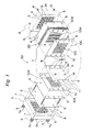
- Fig. 1 is a perspective view schematically showing the structure of a fuel cell stack 30 being one example of a polymer electrolyte fuel cell (PEFC) according to a first embodiment of the present invention in a partially exploded manner.
- the fuel cell stack 30 includes, at its central portion, a cell stacked product 20 which is made up of a plurality of unit cell modules (cells) 1 being stacked.
- a current collector 2 and an end plate 3 are disposed, the end plate 3 having on its inner plane a multiple internal springs 4 as one example of the elastic body.
- fastening bolts 7 each having an external spring 5 fitted to their respective head portions 7a penetrate from one end portion of the cell stacked product 20 through bolt holes 6 formed at the corners of each of the end plate 3, the current collector 2, the cell stacked product 20, the current collector 2, and the end plate 3, and are fastened by having nuts 8 screwed.
- the cells 1 are stacked by sixty pieces to structure the cell stacked product 20, and fastened by the fastening bolts 7 inserted into the bolt holes 6 and the nuts 8, as one example of the fastening member.
- the fastening member is not limited to those structured with the fastening bolts 7 and the nuts 8, and may be other structure such as fastening bands.
- each of the current collectors 2 is a gold-plated copper plate, which is disposed at each of both the outer sides of the cell stacked product 20, such that the generated electricity is collected efficiently.
- a metal material exhibiting an excellent electric conductivity e.g., iron, stainless steel, aluminum, or the like maybe employed.
- the current collector 2 may be surface-treated by tin plating, or nickel plating, or the like.
- the end plate 3 using an electrically insulating material for insulating electricity is disposed, so as to also serve as an insulator.
- the end plates 3 are prepared by injection molding using polyphenylene sulfide resin.
- Pipes 3a integrated with the end plates 3 are pressed against manifolds of the cell stacked product 20 to establish communication, via gaskets (not shown) that function as one example of the manifold-use sealing members and that have manifold-use through holes.
- the fastening dimension is managed such that, for example, a load of 8.4 kN is applied to the cell stacked product 20 when fastened in a state where the multiple internal springs 4 on the inner side of each end plate 3 that apply load to the cell 1 are disposed evenly and in a centered manner at the projection portion of the electrolyte membrane electrode assembly (hereinafter referred to as "MEA") 9, that is, on the inner side of the cell 1.
- MEA electrolyte membrane electrode assembly
- the external springs 5 are disposed between the head portions 7a of their respective fastening bolts 7 and the outer surface of the end plate 3, and are adjusted by a plurality of fastening bolts 7 and a plurality of nuts 8 when assembled, and fastened by 10 kN, for example.
- the cell 1 is structured as follows: the MEA 9 having the gaskets 14, each as one example of the sealing member, at its circumferential portion of both the front and back surfaces, is clamped between paired electrically conductive separators 10, specifically, an anode-side separator 10A and a cathode-side separator 10C; and further, on the outer side of one separator, e.g., the cathode-side separator 10C, a coolant separator 10W is disposed.
- each of the separators 10A and 10C and the MEA 9 paired through holes through which the fuel gas, the oxidant gas, and the coolant flow, respectively, i.e., manifold holes 11 (11A, 11C, and 11W) are bored. Further, at the coolant separator 10W, paired through holes through which the fuel gas, the oxidant gas, and the coolant flow, respectively, i.e., manifold holes 11 (11A, 11C, and 11W) are bored.
- the manifold holes 11 are stacked to one another to establish communication with one another, to thereby independently form the fuel gas-use manifold 11A, the oxidant gas-use manifold 11C, and the coolant-use manifold 11W.
- the body portion 9a of the MEA 9 is structured with a polymer electrolyte membrane that selectively transports hydrogen ions, and paired electrode layers formed on both the inner and outer sides of the polymer electrolyte membrane inner than the circumferential portion, that is, anode and cathode electrode layers.
- the electrode layers each have a layered structure, in which a gas diffusion layer, and a catalyst layer disposed between the gas diffusion layer and the polymer electrolyte membrane are provided.
- the anode-side separator 10A and the cathode-side separator 10C are flat plate-like, and the plane which is in contact with the MEA 9, that is, the inner plane, is structured to have a shape conforming to the shape of the body portion 9a of the MEA 9 and that of the gasket 14.
- glassy carbon thickness: 3mm
- various manifold holes and the bolt holes 6 pass throughout the separators 10A, 10C, and 10W in the thickness direction.
- the fuel gas flow channel groove 12A and the oxidant gas flow channel groove 12C are formed, respectively.
- the coolant flow channel groove 12W is formed on the inner plane (the plane on the cathode-side separator 10C side) of the separator 10W.
- the various manifold holes, the bolt holes 6, the fuel gas flow channel groove 12A, the oxidant gas flow channel groove 12C, the coolant flow channel groove 12W and the like are formed by cutting work or molding work.
- the gaskets 14 disposed on the front surface and the back surface of the MEA 9, respectively, are each a sealing member structured with an elastic body integrally formed with the MEA 9.
- the gaskets 14 deform so as to conform to the shape of the inner surfaces of the separators 10A and 10C, since the MEA 9 is pressed against the separators 10A and 10C.
- the external circumference of the body portion 9a of the MEA 9 and the external circumference of the manifold holes 11 (11A, 11C, and 11W) are sealed with the gaskets 14 (14A, 14C, and 14W).
- Fig. 2B is a plan view showing the fuel gas-use gasket structure of the MEA 9 adjacent to the fuel gas flow channel groove 12A of the separator 10A of the fuel cell stack shown in Fig. 1 .
- the fuel gas-use gasket 14A is structured to partition such that the space with which the fuel gas-use manifold hole 11A and the fuel gas-use body portion 9aA establish communication, the oxidant gas-use manifold 11C, and the coolant-use manifold 11W become independent of one another.
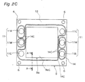
- Fig. 2C is a plan view showing the oxidant gas-use gasket structure of the MEA 9 adjacent to the oxidant gas flow channel groove 12C of the separator 10C of the fuel cell stack shown in Fig. 1 .
- the oxidant gas-use gasket 14C is structured to partition such that the space with which the oxidant gas-use manifold hole 11C and the oxidant gas-use body portion 9aC establish communication, the fuel gas-use manifold 11A, and the coolant-use manifold 11W become independent of one another.
- Fig. 2D is a plan view showing the coolant-use gasket structure of the cathode-side separator 10C or the coolant separator 10W of the fuel cell stack in Fig. 1 .
- the coolant-use gasket 14W is structured to partition such that the space with which the coolant-use manifold hole 11W and the coolant flow channel groove 12W establish communication, the fuel gas-use manifold 11A, and the oxidant gas-use manifold 11C become independent of one another.
- a general sealing member such as squeeze packing or the like made of a heat-resistant material is arranged around the various manifold holes 11.
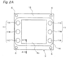
- Fig. 2A is a plan view of the more specific structure of the MEA 9 of the fuel cell stack 30 according to the first embodiment.
- a frame body 13 is molded at the external circumference portion of the MEA 9, and the gasket 14 is molded and disposed at the body portion 9a of the MEA 9 and the external circumference of each of the manifold holes 11.
- Fig. 3B shows a partial cross section taken along A-A of the body portion 9a of the MEA 9, the frame body 13, and the gasket 14.
- Fig. 3A is a partial cross-sectional view of the gasket structure of the conventional MEA 109 cut along the similar part.
- Fig. 3B is a partial cross-sectional view of the structure of the gasket 14 according to the first embodiment.
- the frame body 113, 13 made of resin is molded at the external circumference of the MEA 109, 9.
- the gasket 114, 14 are integrally molded.
- a gasket 114-1, 14-1 and a gasket 114-2, 14-2 molded on the top and bottom surface of the frame body 113, 13, respectively, are identical to each other in the cross-sectional shape.
- the gasket 14-1 and the gasket 14-2 respectively formed on the top and bottom surface of the frame body 13 are identical in the up-and-down direction to each other in the cross-sectional shape.
- the present invention is not limited thereto.
- the bottom surface which is more rigorously demanded to exhibit sealing performance than the top surface can exhibit the significant effect of the first embodiment.
- the effect of the double seal can also be exhibited by disposing gaskets of the double seal of the shapes according to an after-mentioned application example shown in Figs. 6A and 7A on the top and bottom surfaces, respectively.
- gaskets of the double seal of the shapes according to an after-mentioned application example shown in Figs. 6A and 7A on the top and bottom surfaces, respectively.
- fiberglass-added polypropylene can be used as the frame body 13
- one type of olefinic thermoplastic elastomer can be used as the gasket 14.
- thermosetting resin is extremely high in flowability when being molded, and the electrode of the MEA 9 is impregnated therewith. Therefore, thermoplastic resin is preferable.
- Fig. 3A is a partial cross-sectional view showing the structure of the conventional gasket 114, in which a sealing lip 114a is single-stepped bell-shaped structure.
- Fig. 3B is a partial cross-sectional view showing the seal structure according to the first embodiment. Since the top and bottom gaskets 14-1 and 14-2 are identical to each other in shape, in the following, a description will be given of the top gasket 14-1 as a representative example.
- the gasket 14-1 integrally molded with the frame body 13 is structured with a quadrilateral frame-shaped first sealing lip 15 and a quadrilateral frame-shaped second sealing lip 16 which are continuous to form two rows in parallel to each other in the plane of the MEA 9, and in parallel to each side of the quadrilateral shape being the outer shape of the body portion 9a of the MEA 9.
- the first sealing lip 15 and the second sealing lip 16 are each structured to be two-stepped bell-shaped in the top to bottom direction (thickness direction) in Fig. 3B .
- the first sealing lip 15 disposed on the outside air side is formed with: a first bottom side bell-shaped portion 15M of the first step raised from the front surface of the frame body 13; a first bottom side apex 15B as an apex of the vertical cross-sectional circular shape of the first bottom side bell-shaped portion 15M; a first top side bell-shaped portion 15N of the second step further raised from nearby the apex 15B of the first bottom side bell-shaped portion 15M; and a first top side apex 15C as an apex of the vertical cross-sectional circular shape of the first top side bell-shaped portion 15N.
- the diameter of the bottom plane portion of the first top side bell-shaped portion 15N is set to be smaller than the diameter nearby the apex 15B of the first bottom side bell-shaped portion 15M, such that the step portion is formed at the connectionbetween the first top side bell-shaped portion 15N and the first bottom side bell-shaped portion 15M.
- the second sealing lip 16 disposed on the body portion 9a side (the left side in Fig.
- the diameter of the bottom plane portion of the second top side bell-shaped portion 16N is set to be smaller than the diameter nearby the apex 16B of the second bottom side bell-shaped portion 16M, such that the step portion is formed at the connection between the second top side bell-shaped portion 16N and the secondbottom side bell-shapedportion 16M.
- the bottom portion of the first bottom side bell-shaped portion 15M and the bottom portion of the second bottom side bell-shaped portion 16M are integrated to form a continuing portion 14P, such that the portion between the first and second sealing lips 15 and 16 attains a continuous shape.
- a height H2 of the continuing portion 14P between the first and second sealing lips 15 and 16 is set to be lower than a height H1 which is from the frame body 13 to the separator retaining position after the stack is assembled.
- H1 > H2 By establishing the relationship of H1 > H2 in this manner, a reduction in the reaction force is realized, and the double seal can be molded in a narrow range.
- the height H2 of the continuing portion 14P by setting the height H2 of the continuing portion 14P to be as high as or higher than the height H1 which is from the frame body 13 to the separator retaining position after the stack is assembled, it necessitates elastic deformation of the first and second sealing lips 15 and 16 and the continuing portion 14P to the height H1 of the separator retaining position.
- the height of each of the first bottom side apex 15B, the first top side apex 15C, the second bottom side apex 16B, and the second top side apex 16C is set to be higher than the height H1 which is to the separator retaining position after the stack is assembled, such that the stack surely elastically deforms when assembled.
- Fig. 10A is a partial enlarged cross-sectional view of the gasket structure of the fuel cell stack according to the first embodiment shown in Fig. 3B .
- Fig. 10B is an enlarged cross-sectional view of the gasket shown in Fig. 10A being pressed by the separator.
- W > h > 0 and W > d > 0, where: a width of the bottom plane of each of the bottom side bell-shaped portions 15M and 16M is W; a width of the continuing portion 14P is d; a height from the bottom plane of the bottom side bell-shaped portions 15M and 16M to the apex portions 15C and 16C of the top side bell-shaped portions 15N and 16N is h.
- the reason why W > h > 0 is preferable is that it is advantageous for the stability of the sealing lips 15 and 16.
- the sealing lips 15 and 16 are prone to be unstable.
- the reason why W > d is preferable is that, when the width d is excessively great, the entire size increases and a space volume of a concave portion 72 formed at the continuing portion 14P between the two sealing lips 15 and 16 becomes great when the sealing lips 15 and 16 are compressed.
- the space volume of the concave portion 72 becomes great in a case where the temperature of the moisture entered the space at the concave portion 72 and drops to enter a frozen state, the volume of water increases when the water freezes.
- the entire size further increases; the interval formed in the double seal structure further increases; and the space volume of the concave portion 72 further increases.
- the separator 10 at each of the top and bottom of the sealing lips 15 and 16 shown in Fig. 10A is greater in strength than the seal material, the force generated in accordance with an increase in the volume of moisture (water) acts on the sealing lips 15 and 16 than on each separator 10, to push the sealing lips 15 and 16 in right and left directions in Fig. 10B , making the sealing lips 15 and 16 prone to collapse.
- the dimension must be set such that the volume of the space at the concave portion 72 is minimized. To this end, the relationship W > d must be satisfied.
- the reason why d > 0 is preferable is that, in a case where no space at the concave portion 72 is left when the sealing lips 15 and 16 are compressed, the two sealing lips 15 and 16 push each other when the sealing lips 15 and 16 are compressed, making the sealing lips 15 and 16 prone to collapse. Therefore, it is not preferable. In order to prevent such a situation, the width d must at least assume a positive value.
- sealing lips 15 and 16 are effective when they each are a two-stepped lip (two-stepped bell-shaped structure) structured with the bottom side bell-shaped portions 15M and 16M and the top side bell-shaped portions 15N and 16N, for the purpose of securing a prescribed sealing resistance to pressure while reducing the fastening pressure.
- the fastening pressure represented by the area of the cross-hatched portion is smaller in Fig. 11D of the first embodiment than in Fig. 11B of the conventional example.
- the fasteningpressure is reduced.
- the peak surface pressure P MAX is substantially the same in Figs. 11B and 11D .
- a double-bell type i.e., a structure being two-stepped bell-shaped structure and including a plurality of top-side bell-shaped portions
- a double-bell type i.e., a structure being two-stepped bell-shaped structure and including a plurality of top-side bell-shaped portions
- the other sealing lip 16 can be included in the similar manner.
- the peak surface pressure P MAX higher than the gas pressure is produced.
- the peak surface pressure P MAX can be produced at two places, whereby the sealing function can more stably be exhibited.
- the peak surface pressure P MAX at each of the two places shown in Fig. 11F are substantially the same as in Figs. 11B and 11D .
- the first sealing lip 15 and the second sealing lip 16 are mirror symmetric as to the entire top side bell-shaped portions 15N and 16N and part of the bottom side bell-shaped portions 15M and 16M.
- the first bottom side apex 15B and the second bottom side apex 16B are identical to each other in the radius of curvature of the apex
- the first top side apex 15C and the second top side apex 16C are identical to each other in the radius of curvature of the apex.
- the present invention is not limited thereto.
- the first top side apex 15C and the second top side apex 16C may be different in the radius of curvature.
- the following correlation is preferably satisfied: R 1 ⁇ 0.5 ⁇ R 2 , where the radius of curvature for each of the first bottom side apex 15B and the second bottom side apex 16B is R 1 , and the radius of curvature for each of the first top side apex 15C and the second top side apex 16C is R 2 .
- the radius of curvature R 2 is desirably 0.2 to 0.6 mm. In the first embodiment, 0.3 mm may be employed as the radius of curvature R 2 .
- each of the first and second sealing lips 15 and 16 as the two-stepped bell-shaped portion, and setting the radius of curvatures R 1 and R 2 of the apexes of the two-stepped bell-shaped portion to satisfy R 1 ⁇ 0.5 ⁇ R 2 , elastic deformation takes place at two places of the first top side apex 15C and the second top side apex 16C of their respective first and second sealing lips 15 and 16, whereby sealing is performed in a centered manner to the separator 10A or 10C (in other words, the sealing performance is improved in a centered manner on the center line passing through the apex of the first top side apex 15C in the cross section).
- the sealing performance is improved in a centered manner on the center line passing through the apex of the first top side apex 15C in the cross section.
- the apex shape of the first sealing lip 15 and that of the second sealing lip 16 are set to be identical to each other. However, so long as the above-stated correlation is satisfied, the foregoing effect can be exhibited even the first sealing lip 15 and the second sealing lip 16 are different from each other in the shape of the apex.
- the center position of the radius of curvature R 1 of each of the bottom-side apexes 15B and 16B of their respective bottom side bell-shaped portions 15M and 16M and the center position of the radius of curvature R 2 of each of the top-side apexes 15C and 16C of the top side bell-shaped portions 15N and 16N are aligned on one line.
- the center position of the radius of curvature R 2 of the top-side apexes 15C and 16C can be shifted, with reference to the center position of the radius of curvature R 1 of the bottom-side apexes 15B and 16B, toward the MEA 9 side or toward the outside air side, within a range where the radius of curvature R 1 of the bottom-side apexes 15B and 16B and the end portion of the radius of curvature R 2 of the top-side apexes 15C and 16C match with each other.
- a vertex angle ⁇ of each of the first and second sealing lips 15 and 16 is equal to or more than 18°.
- the upper limit value of the vertex angle ⁇ is 90 degrees.
- a ratio (H/D) of a total height of the first and second sealing lips 15 and 16 (the dimension from the front surface of the frame body 13 to the apex of the second sealing lip 16 in the thickness direction) H and an entire width D (sum of the width of both the first and second sealing lips 15 and 16 (the dimension from the outer edge of the first sealing lip 15 to the inner edge of the second sealing lip 16)) is desirably H/D ⁇ 0.6.
- the dimension H in the thickness direction from the front surface of the external circumference of the membrane electrode assembly to the apex of the top side bell-shaped portion is desirably equal to or less than 60%.
- the lower limit value of the ratio (H/D) is 0.1. When the lower limit value of the ratio (H/D) is less than 0.1, the sealing effect cannot be improved while the amount of the material to be used increases.
- the optimum entire width D is 0.5 to 5.0 mm. It is to be noted that, here, the width refers to a dimension perpendicular to the thickness direction of the sealing lips, and that is along a direction perpendicular to the extending direction of the sealing lips.
- vertex angle ⁇ 18°
- H/D 0.6 as the ratio (H/D) between the height H and the entire width D.
- the vertex angle ⁇ is smaller than 18°, or when the ratio (H/D) between the height H and the entire width D of the first and second sealing lips 15 and 16 is greater than 0.6, the apexes of the first and second sealing lips 15 and 16 become unstable and may collapse sideways when applied with fastening load when the stack is assembled. Occurrence of such a sideways collapse prevents the sealing performance from being exhibited.
- the first and second sealing lips 15 and 16 are structured to be two-stepped, and the top side bell-shaped portions 15N and 16N of the second step, which are two-dimensionally smaller than the bottom side bell-shaped portions 15M and 16M of the first step and each of which have a small radius of curvature in terms of cross section, are disposed on the bottom side bell-shaped portions 15M and 16M.
- the top side bell-shaped portions 15N and 16N are brought into contact with the separators 10A and 10C, whereby the top side bell-shaped portions 15N and 16N function as deformation facilitated portions that can elastically deform with ease to a greater extent than the bottom side bell-shaped portions 15M and 16M do.
- the top side bell-shaped portions 15N and 16N elastically deform greatly as the deformation facilitated portions, the apex portions of the bottom side bell-shaped portions 15M and 16M deform, and the bottom side bell-shaped portions 15M and 16M function as seal area enlarging portions that enlarge the seal area between the separators 10A and 10C.
- the apexes of the first and second sealing lips 15 and 16 are stably brought into contact with the opposite face of the separator 10A or 10C when the fastening load is applied when the stack is assembled, to start elastically deform.
- the sideways collapse of the first and second sealing lips 15 and 16 can surely be prevented, and the sealing performance can surely be exhibited.
- a reduction in both the size of the stack 30 and the thickness of the unit cell module 1 can surely be achieved.
- the first and second sealing lips 15 and 16 are brought into contact with the opposite face of the separator 10A or 10C to exhibit the sealing performance, whereby double sealing can be achieved, and it becomes possible to provide a double seal structure which can surely secure the sealing performance.
- the sealing performance improves as compared to the conventional example, it becomes possible to achieve the effect of reduced seal height and also the reduced reaction force as compared to the conventional example.
- a material having no adhesiveness is used for each of the frame body 13 and the gasket 14, setting a great value for the entire width D or increasing the surface roughness of the surface of a portion of the frame body 13 where the gasket 14 is to be formed can contribute toward improving the sealing performance.
- the gasket 14 can be formed with a resin material such as synthetic rubber, EPDM, silicone, or the like.
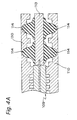
- Fig. 4A is a partial cross-sectional view of the unit cell module 1 in a case where the double seal is structured by juxtaposing the two gaskets 114 of the conventional shape so as to contact the separators 110.
- Fig. 4B is a partial cross-sectional view of the unit cell module 1 with the gaskets 14 of the shape according to the first embodiment. It is to be noted that, Figs. 4A and 4B each show the separator shape such that the seal groove shape of the separators can clearly be seen, and do not show the cross section when fastened. They each show the state where the gaskets 114 and the separators 110 are virtually assembled and, therefore, each seal does not elastically deform at all.
- Fig. 4C is a graph showing a simulation result obtained by comparing the seal reaction force which is produced when the double seal is structured with the conventional gasket shape shown in Fig. 4A , and the seal reaction force which is produced with the gasket shape according to the first embodiment of the present invention shown in Fig. 4B .
- the simulation was carried out with the general-purpose structural analysis software ABAQUS.
- the reaction force is reduced by up to about 40% as compared to the conventional example, and a reduction in the fastening pressure to the stack 30 can be possible. Further, a result similar to the simulation was obtained by an experiment.
- each gasket 14 of the first embodiment of the present invention requires a smaller occupying area of the gasket 14 in the unit cell module 1, as compared to the double seal structure which is structured by juxtaposing two gaskets 114 of the shape of the conventional example. Therefore, it becomes possible to save the space, and a reduction in size of the stack 30 can be achieved.
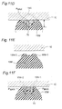
- Fig. 4E is a partial cross-sectional view of the fastened unit cell module 1 in which the two gaskets 114 of the conventional shape shown in Fig. 4A are juxtaposed to each other and disposed so as to be brought into contact with the separators 110 to structure the double seal, in which each seal elastically deforms.
- Fig. 4F is a partial cross-sectional view of the fastened unit cell module 1 with the gaskets 14 of the shape of the first embodiment shown in Fig. 4B , in which each seal elastically deforms.
- Figs. 5A and 5B each show a variation example of the first embodiment.
- Fig. 5A shows the structure in which the bottom surface of each gasket 14 is buried on the frame body 13 side.
- a concave portion 13a is previously formed on each surface of the frame body 13 where each gasket 14 is to be disposed, and the gasket 14 is fitted in the concave portion 13a.
- the frame body 13 can stop the gasket 14 from spreading in the plane direction at the edge portion 13b when the gasket 14 is fastened. Therefore, the sealing performance further improves. Further, as shown in Fig.
- Fig. 6A shows a partial cross-sectional view of a seal structure according to a second embodiment of the present invention. While the first sealing lip 15 on the outside air side has the two-stepped lip structure which is identical to that in the first embodiment, a third sealing lip 18 on the MEA side has the single-stepped lip structure.
- the third sealing lip 18 may be bell-shaped with one apex in the vertical cross-sectional circular shape, instead of being the two-stepped bell-shaped. In this manner, in a situation where the inside and the outside are differing in environment from each other, by employing the sealing lip shape suitable for the corresponding environment, depending on the operation condition or the environmental condition, it becomes possible to achieve the effect of a further improvement in the sealing performance for a long period in addition to the effect of the first embodiment.
- Fig. 6A shows the separator shape such that the seal groove shape of the separators can clearly be seen, and does not show the cross section when fastened.
- Fig. 7A shows the state where the MEA and the separators are virtually assembled and, therefore, each seal does not elastically deform at all.
- Fig. 6B is a partial cross-sectional view of the fastened gasket structure according to the second embodiment, in which each seal elastically deforms.
- the sealing lip that is in the unit cell module 1 and that is in contact with the MEA 9 must have combined features of water resistance, water vapor resistance, and pressure resistance, and the sealing lip in contact with the outside air must retain durability against the air.
- the contact area of the third sealing lip 18 relative to the separator 10A or 10C is enlarged than that of the second sealing lip 16. Accordingly, even in a case where the internal pressure of the fuel gas and the oxidant gas is loaded, it becomes possible to achieve a structure with a great pressure resistance, and to further secure the sealing performance more surely for a longer period. Still further, it becomes possible to achieve a structure with further higher resistance to water vapor and also to a water environment. That is, when an internal pressure on the MEA side is applied extremely greatly, when employing the shape of the third sealing lip 18, a further improvement in the sealingperformance for a longperiod can be achieved.
- thermoplastic elastomer having heat resistance can be used as the material of the gasket 14.
- Fig. 7A is a partial cross-sectional view of a seal structure according to a third embodiment useful for understanding the present invention.
- the gasket 14 has a two-stepped bell-shaped structure, in which the second sealing lip 16 on the MEA 9 side is two-stepped.
- the sealing lip 17 on the outside air side is plate-like, while the facing counter separator 10A or 10C is provided with a convex portion 24 which is in a vertical cross-sectional circular shape and convex-shaped.
- the ensured sealing performance can be retained by the second sealing lip 16, and further, it becomes possible to secure the sealing performance with the sealing lip 17 on the outside air side and the convex portion 24 using a small fastening force.
- Fig. 7A shows the separator shape such that the seal groove shape of the separators can clearly be seen, and does not show the cross section when fastened. It shows the state where the MEA and the separators are virtually assembled and, therefore, each seal does not elastically deform at all.
- Fig. 7B is a partial cross-sectional view of the fastened gasket structure according to the third embodiment, in which each seal elastically deforms.
- the polymer electrolyte fuel cell-use gasket of the present invention is useful as a fuel cell-use gasket used for a portable power supply, an electric vehicle-use power supply, a household cogeneration system, or the like.
Landscapes
- Life Sciences & Earth Sciences (AREA)
- Engineering & Computer Science (AREA)
- Manufacturing & Machinery (AREA)
- Sustainable Development (AREA)
- Sustainable Energy (AREA)
- Chemical & Material Sciences (AREA)
- Chemical Kinetics & Catalysis (AREA)
- Electrochemistry (AREA)
- General Chemical & Material Sciences (AREA)
- Fuel Cell (AREA)
Claims (4)
- Dichtung (14) zur Verwendung in einer Polymerelektrolytbrennstoffzelle, die in einer Polymerelektrolytbrennstoffzelle mit einem Brennstoffzellenstapel (30) enthalten ist, in dem ein gestapeltes Produkt (20), das durch Verklammern mit einem Befestigungselement (7) über gepaarte Endplatten (3), die jeweils auf beiden Seiten des gestapelten Produkts (20) angeordnet sind, aufgebaut ist, wobei das gestapelte Produkt (20) mit mehreren gestapelten Zellmoduleinheiten (1) strukturiert ist, wobei jede Zellmoduleinheit (1) umfasst: eine Membranelektrodenanordnung (9), ein Dichtelement (14), das an einem äußeren Umfang beider Oberflächen der Membranelektrodenanordnung (9) angeordnet ist, und gepaarte Separatoren (10), die die Membranelektrodenanordnung (9) und das Dichtelement (14) einschließen, wobei
das Dichtelement (14) jeweils an dem äußeren Umfangsabschnitt der beiden Oberflächen der Membranelektrodenanordnung (9) angeordnet ist,
und das Dichtelement (14) zwei Reihen von Dichtlippen (15, 16) umfasst, die parallel zueinander in einer Ein-Ebenen-Weise relativ zu dem Separator (10) kontinuierlich vorgesehen sind,
wenigstens eine äußere Dichtlippe (15) der zwei Reihen von Dichtlippen (15, 16) so geformt ist, dass sie einen oberen glockenförmigen Abschnitt (15N) aufweist, der einem unteren glockenförmigen Abschnitt (15M) überlagert ist, und
ein Radius einer Krümmung an einer Spitze (15B) des unteren glockenförmigen Abschnitts (15M) größer als ein Radius einer Krümmung an einer Spitze (15C) des oberen glockenförmigen Abschnitts (15N) ist, und
wobei ein folgendes Verhältnis erfüllt ist: W > h > 0 und W > d > 0, wobei eine Breite an einer Bodenfläche des unteren glockenförmigen Abschnitts (15M) W ist, ein Abstand von benachbarten unteren glockenförmigen Abschnitten (15M) d ist, eine Höhe von der Bodenebene des unteren glockenförmigen Abschnitts (15M) zu einem Spitzenabschnitt (15c) des oberen glockenförmigen Abschnitts (15n) h ist. - Dichtung (14) zur Verwendung in einer Polymerelektrolytbrennstoffzelle nach Anspruch 1, wobei
unter der Definition, dass der Radius der Krümmung der Spitze (15B) des unteren glockenförmigen Abschnitts (15M) R1 ist und der Radius der Krümmung der Spitze (15C) des oberen glockenförmigen Abschnitts (15N) R2 ist, eine Korrelation zwischen dem Radius der Krümmung R1 und dem Radius der Krümmung R2 die Ungleichung R1 × 0,5 ≥ R2 erfüllt, und
eine Höhe eines Abschnitts zwischen den zwei Reihen von Dichtlippen (15, 16) so geformt ist, dass sie geringer ist als eine Höhe, an der der Separator (10) an jeder der beiden Oberflächen der Membranelektrodenanordnung (9) die zwei Reihen von Dichtlippen (15, 16) befestigt. - Dichtung (14) zur Benutzung in einer Polymerelektrolytbrennstoffzelle nach Anspruch 1 oder 2, wobei
ein Scheitelwinkel des unteren glockenförmigen Abschnitts (15M) und ein Scheitelwinkel des oberen glockenförmigen Abschnitts (15N) jeweils 18° oder mehr beträgt, und
eine Abmessung in Dickenrichtung von einer Bodenfläche der zwei Reihen von Dichtlippen (15, 16) zu der Spitze (15C) des oberen glockenförmigen Abschnitts (15N) relativ zu einer Gesamtbreite senkrecht zu einer Dickenrichtung der zwei Reihen von Dichtlippen (15, 16) und entlang einer Richtung senkrecht zu einer Ausdehnungsrichtung der zwei Reihen von Dichtlippen (15, 16) 60% oder weniger beträgt. - Dichtung (14) zur Verwendung in einer Polymerelektrolytbrennstoffzelle nach einem der Ansprüche 1 bis 3, wobei
ein Querschnitt in der Nähe der Spitze (15C) des oberen glockenförmigen Abschnitts (15N) und ein Querschnitt in der Nähe der Spitze (15B) des unteren glockenförmigen Abschnitts (15N) beide kreisförmig sind.
Applications Claiming Priority (2)
| Application Number | Priority Date | Filing Date | Title |
|---|---|---|---|
| JP2009050077 | 2009-03-04 | ||
| PCT/JP2010/001439 WO2010100906A1 (ja) | 2009-03-04 | 2010-03-03 | 高分子電解質型燃料電池用ガスケット |
Publications (3)
| Publication Number | Publication Date |
|---|---|
| EP2405516A1 EP2405516A1 (de) | 2012-01-11 |
| EP2405516A4 EP2405516A4 (de) | 2012-11-21 |
| EP2405516B1 true EP2405516B1 (de) | 2014-04-30 |
Family
ID=42709473
Family Applications (1)
| Application Number | Title | Priority Date | Filing Date |
|---|---|---|---|
| EP10748505.4A Active EP2405516B1 (de) | 2009-03-04 | 2010-03-03 | Polymerelektrolyt-brennstoffzellendichtung |
Country Status (4)
| Country | Link |
|---|---|
| US (1) | US8962212B2 (de) |
| EP (1) | EP2405516B1 (de) |
| JP (1) | JP4800443B2 (de) |
| WO (1) | WO2010100906A1 (de) |
Families Citing this family (32)
| Publication number | Priority date | Publication date | Assignee | Title |
|---|---|---|---|---|
| CN102484264B (zh) | 2010-03-17 | 2015-02-04 | 日产自动车株式会社 | 燃料电池单元 |
| KR101210638B1 (ko) * | 2010-11-17 | 2012-12-07 | 현대자동차주식회사 | 가스켓을 가지는 연료전지용 분리판 및 이의 제조방법 |
| JP6168641B2 (ja) * | 2011-05-13 | 2017-07-26 | 日産自動車株式会社 | 燃料電池 |
| CA2866812C (en) * | 2012-03-09 | 2017-03-14 | Nissan Motor Co., Ltd. | Fuel cell stack and seal plate used for the same |
| JP6274608B2 (ja) * | 2012-03-15 | 2018-02-07 | 日産自動車株式会社 | 燃料電池 |
| JP5979562B2 (ja) * | 2012-05-17 | 2016-08-24 | パナソニックIpマネジメント株式会社 | 燃料電池及びその製造方法 |
| DE102012020947A1 (de) * | 2012-10-25 | 2014-04-30 | Volkswagen Aktiengesellschaft | Membran-Elektroden-Anordnung sowie Brennstoffzelle mit einer solchen |
| JP6141103B2 (ja) * | 2013-05-27 | 2017-06-07 | Nok株式会社 | 燃料電池のシール構造 |
| JP6082715B2 (ja) * | 2014-06-26 | 2017-02-15 | 住友理工株式会社 | 燃料電池用ゴムガスケット |
| JP6383203B2 (ja) * | 2014-07-25 | 2018-08-29 | Nok株式会社 | プレート一体ガスケットの製造方法 |
| EP3012892B1 (de) * | 2014-10-24 | 2017-07-19 | Swiss Hydrogen SA | Elektrochemische Anordnung zum Stapeln |
| DE102015100740A1 (de) * | 2015-01-20 | 2016-07-21 | Elringklinger Ag | Elektrochemische Einheit für einen Brennstoffzellenstapel |
| JP6414638B2 (ja) * | 2015-06-15 | 2018-11-07 | 日産自動車株式会社 | 燃料電池用電極構造体、金属セパレータ、上記燃料電池用電極構造体と金属セパレータとを用いた燃料電池セル、及び上記燃料電池用電極構造体作製用金型 |
| EP3327841B1 (de) * | 2015-07-13 | 2019-09-18 | Nissan Motor Co., Ltd. | Dichtungsstruktur für eine brennstoffzelle |
| CN107408666B (zh) * | 2015-09-25 | 2021-01-15 | 株式会社东芝 | 非水电解质电池用电极、非水电解质电池及电池包 |
| DE102016205043A1 (de) * | 2016-03-24 | 2017-09-28 | Volkswagen Aktiengesellschaft | Brennstoffzellenstapel und Brennstoffzellensystem mit einem solchen Brennstoffzellenstapel |
| KR101918354B1 (ko) * | 2016-10-12 | 2018-11-14 | 현대자동차주식회사 | 연료전지용 가스켓 |
| JP6597552B2 (ja) | 2016-10-25 | 2019-10-30 | トヨタ自動車株式会社 | ガスケットおよび燃料電池 |
| EP3654403A1 (de) * | 2017-07-12 | 2020-05-20 | NOK Corporation | Dichtung für sekundärbatterie |
| CN107946515B (zh) * | 2017-12-26 | 2023-07-18 | 上汽大众汽车有限公司 | 电池包及其密封机构 |
| EP3783711A4 (de) | 2018-03-30 | 2022-03-16 | Osaka Gas Co., Ltd. | Gestapelter körper elektrochemischer elemente, elektrochemisches element, elektrochemisches modul, elektrochemische vorrichtung und energiesystem |
| CN110571452B (zh) * | 2018-06-05 | 2022-08-19 | Nok株式会社 | 燃料电池用密封垫 |
| JP7103249B2 (ja) * | 2019-01-30 | 2022-07-20 | トヨタ自動車株式会社 | 燃料電池スタック |
| JP7241588B2 (ja) | 2019-03-29 | 2023-03-17 | 大阪瓦斯株式会社 | 電気化学素子、電気化学モジュール、電気化学装置及びエネルギーシステム |
| JP7345267B2 (ja) * | 2019-03-29 | 2023-09-15 | 大阪瓦斯株式会社 | 電気化学素子、電気化学モジュール、電気化学装置及びエネルギーシステム |
| JP7196773B2 (ja) * | 2019-05-31 | 2022-12-27 | トヨタ自動車株式会社 | 燃料電池 |
| JP7309596B2 (ja) * | 2019-12-23 | 2023-07-18 | Nok株式会社 | 燃料電池用接合セパレータ |
| CN114256492B (zh) * | 2020-09-22 | 2024-02-13 | 未势能源科技有限公司 | 密封垫和电化学电池 |
| DE102021203983A1 (de) * | 2021-04-21 | 2022-10-27 | Cellcentric Gmbh & Co. Kg | Einzelzellanordnung für einen Brennstoffzellenstapel |
| EP4562696A2 (de) * | 2022-07-29 | 2025-06-04 | KAMAX Holding GmbH & Co. KG | Brennstoffzelle |
| WO2024106305A1 (ja) * | 2022-11-15 | 2024-05-23 | Nok株式会社 | ガスケットおよびガスケット装置 |
| WO2026082265A1 (en) * | 2024-10-14 | 2026-04-23 | Robert Bosch Gmbh | Cell for an electrochemical energy converter |
Family Cites Families (14)
| Publication number | Priority date | Publication date | Assignee | Title |
|---|---|---|---|---|
| JP3678024B2 (ja) | 1998-10-28 | 2005-08-03 | Nok株式会社 | 燃料電池用カーボン材 |
| JP4530122B2 (ja) * | 2001-03-09 | 2010-08-25 | Nok株式会社 | ガスケット |
| DE10246096A1 (de) | 2002-10-02 | 2004-04-22 | Siemens Ag | Dichtung |
| CN1536698B (zh) | 2003-04-02 | 2010-12-15 | 松下电器产业株式会社 | 燃料电池用电解质膜结构、mea结构及燃料电池 |
| JP4439966B2 (ja) | 2003-04-02 | 2010-03-24 | パナソニック株式会社 | 燃料電池用電解質膜構造、燃料電池用電解質膜−電極接合体構造、及び燃料電池 |
| JP2004311254A (ja) * | 2003-04-08 | 2004-11-04 | Matsushita Electric Ind Co Ltd | 燃料電池のガスシール構造 |
| JP2004360717A (ja) | 2003-06-02 | 2004-12-24 | Nok Corp | ガスケット |
| JP2005016703A (ja) | 2003-06-04 | 2005-01-20 | Nok Corp | ガスケット |
| JP2005050728A (ja) | 2003-07-30 | 2005-02-24 | Nichias Corp | 燃料電池のセパレータ用ゴムガスケット |
| JP2005243293A (ja) * | 2004-02-24 | 2005-09-08 | Nissan Motor Co Ltd | 燃料電池用の固体高分子電解質膜 |
| JP2006156097A (ja) | 2004-11-29 | 2006-06-15 | Matsushita Electric Ind Co Ltd | 燃料電池 |
| JP5062389B2 (ja) | 2005-07-15 | 2012-10-31 | Nok株式会社 | 燃料電池およびその製造方法 |
| JP5093554B2 (ja) | 2006-06-12 | 2012-12-12 | Nok株式会社 | 燃料電池用ガスケット |
| US8642230B2 (en) * | 2007-06-11 | 2014-02-04 | Panasonic Corporation | Electrode-membrane-frame assembly for fuel cell, polyelectrolyte fuel cell and manufacturing method therefor |
-
2010
- 2010-03-03 JP JP2010546161A patent/JP4800443B2/ja active Active
- 2010-03-03 WO PCT/JP2010/001439 patent/WO2010100906A1/ja not_active Ceased
- 2010-03-03 US US13/254,244 patent/US8962212B2/en active Active
- 2010-03-03 EP EP10748505.4A patent/EP2405516B1/de active Active
Also Published As
| Publication number | Publication date |
|---|---|
| JPWO2010100906A1 (ja) | 2012-09-06 |
| JP4800443B2 (ja) | 2011-10-26 |
| US8962212B2 (en) | 2015-02-24 |
| US20110318665A1 (en) | 2011-12-29 |
| EP2405516A1 (de) | 2012-01-11 |
| WO2010100906A1 (ja) | 2010-09-10 |
| EP2405516A4 (de) | 2012-11-21 |
Similar Documents
| Publication | Publication Date | Title |
|---|---|---|
| EP2405516B1 (de) | Polymerelektrolyt-brennstoffzellendichtung | |
| US7833673B2 (en) | Solid polymer electrolytic fuel cell | |
| US8551671B2 (en) | Fuel cell fluid sealing structure | |
| US8371587B2 (en) | Metal bead seal for fuel cell plate | |
| JP4418527B2 (ja) | 燃料電池 | |
| EP2445046B1 (de) | Versiegelungsstruktur für eine brennstoffzelle | |
| US9799898B2 (en) | Fuel cell | |
| CN106549181B (zh) | 用于燃料电池堆的不对称紧凑型金属密封珠 | |
| CA2644787C (en) | Fuel cell having porous body and reaction gas leakage prevention section, and method for producing the same | |
| US9660276B2 (en) | Fuel cell including separator with outer ends placed inward of fluid passages formed in frame | |
| US20110236786A1 (en) | Fuel cell | |
| WO2013161200A1 (en) | Solid polymer electrolyte type fuel cell, and electrolyte membrane-electrode-frame assembly | |
| US9196911B2 (en) | Fuel cell gas diffusion layer integrated gasket | |
| EP1932199B1 (de) | Integrierte abdichtung für eine brennstoffzellenbaugruppe und brennstoffzellenstapel | |
| CN109546193B (zh) | 燃料电池堆 | |
| US20070042255A1 (en) | Seal for fuel cell | |
| JP2012195128A (ja) | 高分子電解質型燃料電池用ガスケットおよび高分子電解質型燃料電池 | |
| US20080166608A1 (en) | Fuel Cell and Fuel Cell Separator | |
| US7534518B2 (en) | Cell for solid polymer electrolyte fuel cell with improved gas flow sealing | |
| US9350034B2 (en) | Fuel cell gas diffusion layer integrated gasket | |
| WO2025020041A1 (zh) | 基础框架和电化学能量模块 | |
| JP2008218200A (ja) | 燃料電池スタック、および、燃料電池スタックの製造方法 | |
| JP2006269264A (ja) | 固体高分子電解質形燃料電池 |
Legal Events
| Date | Code | Title | Description |
|---|---|---|---|
| PUAI | Public reference made under article 153(3) epc to a published international application that has entered the european phase |
Free format text: ORIGINAL CODE: 0009012 |
|
| 17P | Request for examination filed |
Effective date: 20111004 |
|
| AK | Designated contracting states |
Kind code of ref document: A1 Designated state(s): AT BE BG CH CY CZ DE DK EE ES FI FR GB GR HR HU IE IS IT LI LT LU LV MC MK MT NL NO PL PT RO SE SI SK SM TR |
|
| DAX | Request for extension of the european patent (deleted) | ||
| A4 | Supplementary search report drawn up and despatched |
Effective date: 20121023 |
|
| RIC1 | Information provided on ipc code assigned before grant |
Ipc: H01M 8/10 20060101ALI20121017BHEP Ipc: H01M 8/02 20060101AFI20121017BHEP Ipc: H01M 8/24 20060101ALI20121017BHEP |
|
| REG | Reference to a national code |
Ref country code: DE Ref legal event code: R079 Ref document number: 602010015627 Country of ref document: DE Free format text: PREVIOUS MAIN CLASS: H01M0008020000 Ipc: H01M0008240000 |
|
| RIC1 | Information provided on ipc code assigned before grant |
Ipc: H01M 8/24 20060101AFI20130812BHEP Ipc: H01M 8/10 20060101ALI20130812BHEP Ipc: H01M 8/02 20060101ALI20130812BHEP |
|
| GRAP | Despatch of communication of intention to grant a patent |
Free format text: ORIGINAL CODE: EPIDOSNIGR1 |
|
| INTG | Intention to grant announced |
Effective date: 20131017 |
|
| GRAS | Grant fee paid |
Free format text: ORIGINAL CODE: EPIDOSNIGR3 |
|
| RIN1 | Information on inventor provided before grant (corrected) |
Inventor name: MORIMOTO, TAKASHI Inventor name: MATSUMOTO, TOSHIHIRO Inventor name: YOSHIMURA, MITSUO Inventor name: YAMAMOTO, YOKO |
|
| GRAA | (expected) grant |
Free format text: ORIGINAL CODE: 0009210 |
|
| AK | Designated contracting states |
Kind code of ref document: B1 Designated state(s): AT BE BG CH CY CZ DE DK EE ES FI FR GB GR HR HU IE IS IT LI LT LU LV MC MK MT NL NO PL PT RO SE SI SK SM TR |
|
| REG | Reference to a national code |
Ref country code: GB Ref legal event code: FG4D Ref country code: CH Ref legal event code: EP |
|
| REG | Reference to a national code |
Ref country code: AT Ref legal event code: REF Ref document number: 665651 Country of ref document: AT Kind code of ref document: T Effective date: 20140515 |
|
| REG | Reference to a national code |
Ref country code: IE Ref legal event code: FG4D |
|
| REG | Reference to a national code |
Ref country code: DE Ref legal event code: R096 Ref document number: 602010015627 Country of ref document: DE Effective date: 20140612 |
|
| REG | Reference to a national code |
Ref country code: AT Ref legal event code: MK05 Ref document number: 665651 Country of ref document: AT Kind code of ref document: T Effective date: 20140430 |
|
| REG | Reference to a national code |
Ref country code: LT Ref legal event code: MG4D |
|
| REG | Reference to a national code |
Ref country code: NL Ref legal event code: VDEP Effective date: 20140430 |
|
| PG25 | Lapsed in a contracting state [announced via postgrant information from national office to epo] |
Ref country code: LT Free format text: LAPSE BECAUSE OF FAILURE TO SUBMIT A TRANSLATION OF THE DESCRIPTION OR TO PAY THE FEE WITHIN THE PRESCRIBED TIME-LIMIT Effective date: 20140430 Ref country code: IS Free format text: LAPSE BECAUSE OF FAILURE TO SUBMIT A TRANSLATION OF THE DESCRIPTION OR TO PAY THE FEE WITHIN THE PRESCRIBED TIME-LIMIT Effective date: 20140830 Ref country code: CY Free format text: LAPSE BECAUSE OF FAILURE TO SUBMIT A TRANSLATION OF THE DESCRIPTION OR TO PAY THE FEE WITHIN THE PRESCRIBED TIME-LIMIT Effective date: 20140430 Ref country code: GR Free format text: LAPSE BECAUSE OF FAILURE TO SUBMIT A TRANSLATION OF THE DESCRIPTION OR TO PAY THE FEE WITHIN THE PRESCRIBED TIME-LIMIT Effective date: 20140731 Ref country code: BG Free format text: LAPSE BECAUSE OF FAILURE TO SUBMIT A TRANSLATION OF THE DESCRIPTION OR TO PAY THE FEE WITHIN THE PRESCRIBED TIME-LIMIT Effective date: 20140730 Ref country code: FI Free format text: LAPSE BECAUSE OF FAILURE TO SUBMIT A TRANSLATION OF THE DESCRIPTION OR TO PAY THE FEE WITHIN THE PRESCRIBED TIME-LIMIT Effective date: 20140430 Ref country code: NL Free format text: LAPSE BECAUSE OF FAILURE TO SUBMIT A TRANSLATION OF THE DESCRIPTION OR TO PAY THE FEE WITHIN THE PRESCRIBED TIME-LIMIT Effective date: 20140430 Ref country code: NO Free format text: LAPSE BECAUSE OF FAILURE TO SUBMIT A TRANSLATION OF THE DESCRIPTION OR TO PAY THE FEE WITHIN THE PRESCRIBED TIME-LIMIT Effective date: 20140730 |
|
| PG25 | Lapsed in a contracting state [announced via postgrant information from national office to epo] |
Ref country code: LV Free format text: LAPSE BECAUSE OF FAILURE TO SUBMIT A TRANSLATION OF THE DESCRIPTION OR TO PAY THE FEE WITHIN THE PRESCRIBED TIME-LIMIT Effective date: 20140430 Ref country code: AT Free format text: LAPSE BECAUSE OF FAILURE TO SUBMIT A TRANSLATION OF THE DESCRIPTION OR TO PAY THE FEE WITHIN THE PRESCRIBED TIME-LIMIT Effective date: 20140430 Ref country code: ES Free format text: LAPSE BECAUSE OF FAILURE TO SUBMIT A TRANSLATION OF THE DESCRIPTION OR TO PAY THE FEE WITHIN THE PRESCRIBED TIME-LIMIT Effective date: 20140430 Ref country code: PL Free format text: LAPSE BECAUSE OF FAILURE TO SUBMIT A TRANSLATION OF THE DESCRIPTION OR TO PAY THE FEE WITHIN THE PRESCRIBED TIME-LIMIT Effective date: 20140430 Ref country code: HR Free format text: LAPSE BECAUSE OF FAILURE TO SUBMIT A TRANSLATION OF THE DESCRIPTION OR TO PAY THE FEE WITHIN THE PRESCRIBED TIME-LIMIT Effective date: 20140430 Ref country code: SE Free format text: LAPSE BECAUSE OF FAILURE TO SUBMIT A TRANSLATION OF THE DESCRIPTION OR TO PAY THE FEE WITHIN THE PRESCRIBED TIME-LIMIT Effective date: 20140430 |
|
| PG25 | Lapsed in a contracting state [announced via postgrant information from national office to epo] |
Ref country code: PT Free format text: LAPSE BECAUSE OF FAILURE TO SUBMIT A TRANSLATION OF THE DESCRIPTION OR TO PAY THE FEE WITHIN THE PRESCRIBED TIME-LIMIT Effective date: 20140901 |
|
| PG25 | Lapsed in a contracting state [announced via postgrant information from national office to epo] |
Ref country code: EE Free format text: LAPSE BECAUSE OF FAILURE TO SUBMIT A TRANSLATION OF THE DESCRIPTION OR TO PAY THE FEE WITHIN THE PRESCRIBED TIME-LIMIT Effective date: 20140430 Ref country code: CZ Free format text: LAPSE BECAUSE OF FAILURE TO SUBMIT A TRANSLATION OF THE DESCRIPTION OR TO PAY THE FEE WITHIN THE PRESCRIBED TIME-LIMIT Effective date: 20140430 Ref country code: DK Free format text: LAPSE BECAUSE OF FAILURE TO SUBMIT A TRANSLATION OF THE DESCRIPTION OR TO PAY THE FEE WITHIN THE PRESCRIBED TIME-LIMIT Effective date: 20140430 Ref country code: SK Free format text: LAPSE BECAUSE OF FAILURE TO SUBMIT A TRANSLATION OF THE DESCRIPTION OR TO PAY THE FEE WITHIN THE PRESCRIBED TIME-LIMIT Effective date: 20140430 Ref country code: BE Free format text: LAPSE BECAUSE OF FAILURE TO SUBMIT A TRANSLATION OF THE DESCRIPTION OR TO PAY THE FEE WITHIN THE PRESCRIBED TIME-LIMIT Effective date: 20140430 Ref country code: RO Free format text: LAPSE BECAUSE OF FAILURE TO SUBMIT A TRANSLATION OF THE DESCRIPTION OR TO PAY THE FEE WITHIN THE PRESCRIBED TIME-LIMIT Effective date: 20140430 |
|
| REG | Reference to a national code |
Ref country code: DE Ref legal event code: R097 Ref document number: 602010015627 Country of ref document: DE |
|
| PLBE | No opposition filed within time limit |
Free format text: ORIGINAL CODE: 0009261 |
|
| STAA | Information on the status of an ep patent application or granted ep patent |
Free format text: STATUS: NO OPPOSITION FILED WITHIN TIME LIMIT |
|
| PG25 | Lapsed in a contracting state [announced via postgrant information from national office to epo] |
Ref country code: IT Free format text: LAPSE BECAUSE OF FAILURE TO SUBMIT A TRANSLATION OF THE DESCRIPTION OR TO PAY THE FEE WITHIN THE PRESCRIBED TIME-LIMIT Effective date: 20140430 |
|
| 26N | No opposition filed |
Effective date: 20150202 |
|
| REG | Reference to a national code |
Ref country code: DE Ref legal event code: R097 Ref document number: 602010015627 Country of ref document: DE Effective date: 20150202 |
|
| PG25 | Lapsed in a contracting state [announced via postgrant information from national office to epo] |
Ref country code: SI Free format text: LAPSE BECAUSE OF FAILURE TO SUBMIT A TRANSLATION OF THE DESCRIPTION OR TO PAY THE FEE WITHIN THE PRESCRIBED TIME-LIMIT Effective date: 20140430 |
|
| PG25 | Lapsed in a contracting state [announced via postgrant information from national office to epo] |
Ref country code: MC Free format text: LAPSE BECAUSE OF FAILURE TO SUBMIT A TRANSLATION OF THE DESCRIPTION OR TO PAY THE FEE WITHIN THE PRESCRIBED TIME-LIMIT Effective date: 20140430 Ref country code: LU Free format text: LAPSE BECAUSE OF FAILURE TO SUBMIT A TRANSLATION OF THE DESCRIPTION OR TO PAY THE FEE WITHIN THE PRESCRIBED TIME-LIMIT Effective date: 20150303 |
|
| REG | Reference to a national code |
Ref country code: CH Ref legal event code: PL |
|
| REG | Reference to a national code |
Ref country code: FR Ref legal event code: ST Effective date: 20151130 |
|
| REG | Reference to a national code |
Ref country code: IE Ref legal event code: MM4A |
|
| PG25 | Lapsed in a contracting state [announced via postgrant information from national office to epo] |
Ref country code: CH Free format text: LAPSE BECAUSE OF NON-PAYMENT OF DUE FEES Effective date: 20150331 Ref country code: LI Free format text: LAPSE BECAUSE OF NON-PAYMENT OF DUE FEES Effective date: 20150331 Ref country code: IE Free format text: LAPSE BECAUSE OF NON-PAYMENT OF DUE FEES Effective date: 20150303 |
|
| PG25 | Lapsed in a contracting state [announced via postgrant information from national office to epo] |
Ref country code: FR Free format text: LAPSE BECAUSE OF NON-PAYMENT OF DUE FEES Effective date: 20150331 |
|
| PG25 | Lapsed in a contracting state [announced via postgrant information from national office to epo] |
Ref country code: MT Free format text: LAPSE BECAUSE OF FAILURE TO SUBMIT A TRANSLATION OF THE DESCRIPTION OR TO PAY THE FEE WITHIN THE PRESCRIBED TIME-LIMIT Effective date: 20140430 |
|
| PG25 | Lapsed in a contracting state [announced via postgrant information from national office to epo] |
Ref country code: HU Free format text: LAPSE BECAUSE OF FAILURE TO SUBMIT A TRANSLATION OF THE DESCRIPTION OR TO PAY THE FEE WITHIN THE PRESCRIBED TIME-LIMIT; INVALID AB INITIO Effective date: 20100303 Ref country code: SM Free format text: LAPSE BECAUSE OF FAILURE TO SUBMIT A TRANSLATION OF THE DESCRIPTION OR TO PAY THE FEE WITHIN THE PRESCRIBED TIME-LIMIT Effective date: 20140430 |
|
| PG25 | Lapsed in a contracting state [announced via postgrant information from national office to epo] |
Ref country code: TR Free format text: LAPSE BECAUSE OF FAILURE TO SUBMIT A TRANSLATION OF THE DESCRIPTION OR TO PAY THE FEE WITHIN THE PRESCRIBED TIME-LIMIT Effective date: 20140430 |
|
| PG25 | Lapsed in a contracting state [announced via postgrant information from national office to epo] |
Ref country code: MK Free format text: LAPSE BECAUSE OF FAILURE TO SUBMIT A TRANSLATION OF THE DESCRIPTION OR TO PAY THE FEE WITHIN THE PRESCRIBED TIME-LIMIT Effective date: 20140430 |
|
| PGFP | Annual fee paid to national office [announced via postgrant information from national office to epo] |
Ref country code: DE Payment date: 20240320 Year of fee payment: 15 |
|
| PGFP | Annual fee paid to national office [announced via postgrant information from national office to epo] |
Ref country code: GB Payment date: 20250321 Year of fee payment: 16 |
|
| REG | Reference to a national code |
Ref country code: DE Ref legal event code: R119 Ref document number: 602010015627 Country of ref document: DE |
|
| PG25 | Lapsed in a contracting state [announced via postgrant information from national office to epo] |
Ref country code: DE Free format text: LAPSE BECAUSE OF NON-PAYMENT OF DUE FEES Effective date: 20251001 |