EP2406540B1 - Lichtausgabesystem zur projektion von mustern - Google Patents
Lichtausgabesystem zur projektion von mustern Download PDFInfo
- Publication number
- EP2406540B1 EP2406540B1 EP10710674.2A EP10710674A EP2406540B1 EP 2406540 B1 EP2406540 B1 EP 2406540B1 EP 10710674 A EP10710674 A EP 10710674A EP 2406540 B1 EP2406540 B1 EP 2406540B1
- Authority
- EP
- European Patent Office
- Prior art keywords
- light
- output
- array
- optical
- pitch
- Prior art date
- Legal status (The legal status is an assumption and is not a legal conclusion. Google has not performed a legal analysis and makes no representation as to the accuracy of the status listed.)
- Active
Links
Images


Classifications
-
- F—MECHANICAL ENGINEERING; LIGHTING; HEATING; WEAPONS; BLASTING
- F21—LIGHTING
- F21S—NON-PORTABLE LIGHTING DEVICES; SYSTEMS THEREOF; VEHICLE LIGHTING DEVICES SPECIALLY ADAPTED FOR VEHICLE EXTERIORS
- F21S10/00—Lighting devices or systems producing a varying lighting effect
-
- F—MECHANICAL ENGINEERING; LIGHTING; HEATING; WEAPONS; BLASTING
- F21—LIGHTING
- F21V—FUNCTIONAL FEATURES OR DETAILS OF LIGHTING DEVICES OR SYSTEMS THEREOF; STRUCTURAL COMBINATIONS OF LIGHTING DEVICES WITH OTHER ARTICLES, NOT OTHERWISE PROVIDED FOR
- F21V23/00—Arrangement of electric circuit elements in or on lighting devices
- F21V23/04—Arrangement of electric circuit elements in or on lighting devices the elements being switches
-
- F—MECHANICAL ENGINEERING; LIGHTING; HEATING; WEAPONS; BLASTING
- F21—LIGHTING
- F21V—FUNCTIONAL FEATURES OR DETAILS OF LIGHTING DEVICES OR SYSTEMS THEREOF; STRUCTURAL COMBINATIONS OF LIGHTING DEVICES WITH OTHER ARTICLES, NOT OTHERWISE PROVIDED FOR
- F21V5/00—Refractors for light sources
- F21V5/002—Refractors for light sources using microoptical elements for redirecting or diffusing light
-
- F—MECHANICAL ENGINEERING; LIGHTING; HEATING; WEAPONS; BLASTING
- F21—LIGHTING
- F21V—FUNCTIONAL FEATURES OR DETAILS OF LIGHTING DEVICES OR SYSTEMS THEREOF; STRUCTURAL COMBINATIONS OF LIGHTING DEVICES WITH OTHER ARTICLES, NOT OTHERWISE PROVIDED FOR
- F21V5/00—Refractors for light sources
- F21V5/007—Array of lenses or refractors for a cluster of light sources, e.g. for arrangement of multiple light sources in one plane
-
- F—MECHANICAL ENGINEERING; LIGHTING; HEATING; WEAPONS; BLASTING
- F21—LIGHTING
- F21V—FUNCTIONAL FEATURES OR DETAILS OF LIGHTING DEVICES OR SYSTEMS THEREOF; STRUCTURAL COMBINATIONS OF LIGHTING DEVICES WITH OTHER ARTICLES, NOT OTHERWISE PROVIDED FOR
- F21V5/00—Refractors for light sources
- F21V5/008—Combination of two or more successive refractors along an optical axis
-
- F—MECHANICAL ENGINEERING; LIGHTING; HEATING; WEAPONS; BLASTING
- F21—LIGHTING
- F21V—FUNCTIONAL FEATURES OR DETAILS OF LIGHTING DEVICES OR SYSTEMS THEREOF; STRUCTURAL COMBINATIONS OF LIGHTING DEVICES WITH OTHER ARTICLES, NOT OTHERWISE PROVIDED FOR
- F21V5/00—Refractors for light sources
- F21V5/02—Refractors for light sources of prismatic shape
-
- F—MECHANICAL ENGINEERING; LIGHTING; HEATING; WEAPONS; BLASTING
- F21—LIGHTING
- F21V—FUNCTIONAL FEATURES OR DETAILS OF LIGHTING DEVICES OR SYSTEMS THEREOF; STRUCTURAL COMBINATIONS OF LIGHTING DEVICES WITH OTHER ARTICLES, NOT OTHERWISE PROVIDED FOR
- F21V5/00—Refractors for light sources
- F21V5/04—Refractors for light sources of lens shape
- F21V5/048—Refractors for light sources of lens shape the lens being a simple lens adapted to cooperate with a point-like source for emitting mainly in one direction and having an axis coincident with the main light transmission direction, e.g. convergent or divergent lenses, plano-concave or plano-convex lenses
-
- F—MECHANICAL ENGINEERING; LIGHTING; HEATING; WEAPONS; BLASTING
- F21—LIGHTING
- F21Y—INDEXING SCHEME ASSOCIATED WITH SUBCLASSES F21K, F21L, F21S and F21V, RELATING TO THE FORM OR THE KIND OF THE LIGHT SOURCES OR OF THE COLOUR OF THE LIGHT EMITTED
- F21Y2105/00—Planar light sources
- F21Y2105/10—Planar light sources comprising a two-dimensional [2D] array of point-like light-generating elements
-
- F—MECHANICAL ENGINEERING; LIGHTING; HEATING; WEAPONS; BLASTING
- F21—LIGHTING
- F21Y—INDEXING SCHEME ASSOCIATED WITH SUBCLASSES F21K, F21L, F21S and F21V, RELATING TO THE FORM OR THE KIND OF THE LIGHT SOURCES OR OF THE COLOUR OF THE LIGHT EMITTED
- F21Y2105/00—Planar light sources
- F21Y2105/10—Planar light sources comprising a two-dimensional [2D] array of point-like light-generating elements
- F21Y2105/12—Planar light sources comprising a two-dimensional [2D] array of point-like light-generating elements characterised by the geometrical disposition of the light-generating elements, e.g. arranging light-generating elements in differing patterns or densities
-
- F—MECHANICAL ENGINEERING; LIGHTING; HEATING; WEAPONS; BLASTING
- F21—LIGHTING
- F21Y—INDEXING SCHEME ASSOCIATED WITH SUBCLASSES F21K, F21L, F21S and F21V, RELATING TO THE FORM OR THE KIND OF THE LIGHT SOURCES OR OF THE COLOUR OF THE LIGHT EMITTED
- F21Y2105/00—Planar light sources
- F21Y2105/10—Planar light sources comprising a two-dimensional [2D] array of point-like light-generating elements
- F21Y2105/14—Planar light sources comprising a two-dimensional [2D] array of point-like light-generating elements characterised by the overall shape of the two-dimensional [2D] array
- F21Y2105/16—Planar light sources comprising a two-dimensional [2D] array of point-like light-generating elements characterised by the overall shape of the two-dimensional [2D] array square or rectangular, e.g. for light panels
-
- F—MECHANICAL ENGINEERING; LIGHTING; HEATING; WEAPONS; BLASTING
- F21—LIGHTING
- F21Y—INDEXING SCHEME ASSOCIATED WITH SUBCLASSES F21K, F21L, F21S and F21V, RELATING TO THE FORM OR THE KIND OF THE LIGHT SOURCES OR OF THE COLOUR OF THE LIGHT EMITTED
- F21Y2115/00—Light-generating elements of semiconductor light sources
- F21Y2115/10—Light-emitting diodes [LED]
-
- Y—GENERAL TAGGING OF NEW TECHNOLOGICAL DEVELOPMENTS; GENERAL TAGGING OF CROSS-SECTIONAL TECHNOLOGIES SPANNING OVER SEVERAL SECTIONS OF THE IPC; TECHNICAL SUBJECTS COVERED BY FORMER USPC CROSS-REFERENCE ART COLLECTIONS [XRACs] AND DIGESTS
- Y10—TECHNICAL SUBJECTS COVERED BY FORMER USPC
- Y10S—TECHNICAL SUBJECTS COVERED BY FORMER USPC CROSS-REFERENCE ART COLLECTIONS [XRACs] AND DIGESTS
- Y10S362/00—Illumination
- Y10S362/80—Light emitting diode
Definitions
- the present invention relates to a light-output system for forming a controllable pattern of illuminated spots in a distant projection plane.
- LEDs new and improved light-emitting diodes
- new areas of applications have emerged.
- products have been developed that enable a user to create atmospheres using controllable lighting.
- One example of such a product is the LivingColours lamp from Philips which, through its intuitive remote control, gives the user the freedom to discover an infinite range of colors.
- a general object of the present invention is to provide an improved light-output system enabling the formation of controllable light patterns on a wall or similar with a higher luminous efficiency than existing electronic projection devices.
- the invention provides a light-output system, for forming a controllable pattern of illuminated spots in a distant projection plane, the light-output system comprising: a plurality of individually controllable light-output devices arranged in an array of light-output devices with a light-output device pitch; and an optical system arranged between the array of light-output devices and the projection plane, the optical system being configured to project light emitted by the array of light-output devices in the projection plane as a projected array of illuminated spots with a one-to-one relation to the light-output devices, the projected array having a projection pitch being larger than the light-output device pitch.
- light-output device should, in the context of the present application, be understood to refer to any device capable of outputting light, that is, electromagnetic radiation within the visible spectrum.
- the "pitch" of an array refers to the distance between adjacent devices comprised in the array in one of the principal directions of the array. As is understood by the person skilled in the art, a one-dimensional array has one pitch value and a two-dimensional array has two pitch values, which may or may not be equal.
- controllable light patterns can be projected on a wall or similar with a very high luminous efficiency by generating the pattern to be projected using an array of light-output devices and projecting the individual light-output devices to corresponding spots on the wall or similar, the pitch of the array of spots being larger than the pitch of the array of light-output devices.
- the projected array of illuminated spots may advantageously comprise the same number of array elements as the array of light-output devices.
- optical system according to the invention can be made very compact and cost-efficient, since only an array of light-output devices and an optical system without moving parts and/or individually controllable elements are needed to achieve the desired controllable patterns of projected light.
- the optical system arranged between the array of light-output devices and the projection plane may advantageously comprise an array of optical elements having an optical element pitch.
- the optical elements may be focusing lenses.
- the focusing lenses may advantageously have substantially identical focusing properties.
- the optical element pitch of the array of optical elements may be larger than the light-output device pitch and smaller than the projection pitch.
- the optical element pitch may advantageously be larger than the light-output device pitch by a factor ranging between 1 and 1.25, and more advantageously by a factor ranging between 1.05 and 1.18.
- each light-output device may comprise at least a first light-source and a second light-source configured to emit differently colored light. This enables projection of colored patterns.
- a first light-source comprised in a first light-output device may be arranged in relation to the optical element associated with the first light-output device in such a way that light emitted by the first light-source is projected as a spot associated with a second light-source comprised in a second light-output device.
- the second light-output device may be located adjacent to the first light-output device, or the first and second light-output devices may be spaced apart by one or several other light-output devices.
- This light-output device configuration enables controlling the color of a projected spot through mixing of light output by light-sources comprised in different light-output devices.
- the "optical distance" is the physical distance times the refractive index of the medium through which the light travels.
- the optical system may additionally comprise a beam-directing member arranged between the array of optical elements and the projection plane, the beam-directing member being configured to direct light-beams exiting from the array of optical elements towards the projected array of illuminated spots in the projection plane.
- the difference between the optical element pitch and the output element pitch can be made smaller (the optical element pitch and the output element pitch can even be equal), whereby a larger array of optical elements (light-output devices) can be accommodated, which enables higher resolution and/or the formation of a larger projected pattern at a given distance.
- the beam-directing member may comprise an array of directing optical elements, each being configured to direct a light-beam exiting from an associated optical element in the array of optical elements towards an associated spot in the projected array of illuminated spots in the projection plane.
- the light-output system may comprise a beam-directing member arranged between the array of light-output devices and the array of optical elements.
- This beam-directing member may comprise an array of directing optical element in analogy with what is described above.
- the light-output system may advantageously be configured to enable relative movement between the array of light-output devices and the optical system.
- the position one of or both of the array of light-output devices and the optical system may be adjustable.
- the configuration of the projected spots can be adjusted by the user in accordance with the conditions at the location of application of the light-output system.
- the light-output system may be configured to enable adjustment of a distance between the array of light-output devices and the optical system.
- the light-output system can be adapted for different distances to the surface onto which the pattern should be projected and/or different desired overlaps between adjacent spots on the surface.
- the alignment between the array of light-output devices and the optical system may be adjustable, that is, either or both of the array of light-output devices and the optical system may be moveable in a sideways direction, whereby the user can adjust the location of the projected pattern of illuminated spots, while the light-output system remains stationary.
- the light-output system may comprise partitioning walls separating the light-output devices, the partitioning walls being arranged between the array of light-output devices and the optical system.
- the partitioning walls being arranged between the array of light-output devices and the optical system.
- the present invention is mainly described with reference to a light-output system, in which the light-output devices comprise a plurality of differently colored light-emitting diodes (LEDs), and an array of conventional positive lenses.
- the light-output devices comprise a plurality of differently colored light-emitting diodes (LEDs), and an array of conventional positive lenses.
- Fig 1 is an exploded view, schematically illustrating an exemplary light-output system 1 projecting a pattern 2 on a distant wall 3 representing a projection plane.
- the light-output system 1 comprises an array 5 of individually controllable light-output devices 6a-c (only three of these are indicated using reference numerals to avoid cluttering the drawing) and an optical system 7 comprising an array of optical elements 9a-c arranged between the light-output devices 6a-c and the projection plane 3.
- the translation from the light-output device pitch P LS to the pitch P spot of the illuminated spots 11a-c is taken care of by the optical system 7 arranged between the array 5 of light-output devices 6a-c and the projection plane 3, and will be further described below with reference to a number of illustrative embodiments of the light-output system in fig 1 .
- Fig 2 is a plane view of the light-output system 1 seen from the projection plane 3 in fig 1 , and light-output devices 6a-c are visible through the optical elements 9a-c.
- each light-output device 6a-c comprises a blue LED 12a, 13a, 14a, a red LED 12b, 13b, 14b, and a green LED 12c, 13c, 14c, and the optical elements 9a-c are provided in the form of lenses arranged with a pitch P lens which is larger than the light-output device pitch P LS .
- fig 2 is a color controllable embodiment
- the principle of the translation from the light-output device pitch P LS to the pitch P spot of the illuminated spots 11a-c in fig 1 will first be described with reference to a simplified monochrome case which is schematically illustrated in fig 3 , and which corresponds to the configuration of fig 2 with the red LEDs 12b, 13b, 14b only.
- each light-source 6b-c may be equipped with collimating optics 15b-c to collimate the light emitted by the light-sources 6b-c somewhat. This is done to ensure that most of the light emitted by the light-sources 6b-c can be captured by the corresponding lens 9b-c.
- the translation from the light-source pitch P LS to the pitch P spot of the illuminated spots in the projection plane 3 is achieved by suitably selecting the geometry of the system, that is, for a given light-source pitch P LS , suitably selecting the distance z o between the light-sources 6b-c and the lenses 9b-c and the pitch P lens of the lenses 9b-c in the lens array 8.
- equation (1) implies that P LS is smaller than P Lens .
- P Lens Preferably, 0.8 P Lens ⁇ P LS ⁇ P Lens . Even more preferred is 0.85 P Lens ⁇ P LS ⁇ 0.95 P Lens .
- z o ⁇ z i Note also that
- the overlap may have an upper limit, which may advantageously be O ⁇ 75%.
- extra overlap can be created by locating a further optical element (not shown in fig 3 ), such as a diffuser (or an array of weak and fine-pitched lenses) close to the plane of the lenses.
- a further optical element such as a diffuser (or an array of weak and fine-pitched lenses) close to the plane of the lenses.
- Fig. 4 is a section view of the partial light-output system in fig 2 along the line A-A', illustrating how differently colored spots can be formed using the light-output system in fig 1 .
- spots of basic colors are projected in the projection plane 3 in such a way that they substantially fully overlap.
- spots of virtually freely controllable colors can be formed without artifacts such as colored fringes etc.
- each lens 11a-c Behind (as seen from the projection plane 3) each lens 11a-c, a triplet of RGB-LEDs 12a-c, 13a-c, 14a-c is located. The light emitted by each LED of these triplets results in a spot of light on the wall 3, as is schematically illustrated in fig 4 for the blue LED 12a, the red LED 13b, and the green LED 14c. The resulting spot 11b will appear white.
- a suitable spacing between the light-sources comprised in the light-output devices 6a-c should be selected.
- each LED of a certain color results in a spot of light on the wall that fully overlaps with the light of a LED of a complementary color of a another triplet by arranging the LEDs 12a-c, 13a-c, 14a-c within each triplet 6a-c with a suitable spacing.
- n is an integer indicating the distance, in units of the spot pitch P spot , between spots resulting from projection of light output by neighboring light-sources in a light-output device 6a-c.
- the differently colored light-sources 12a-c, 13a-c, 14a-c may be provided as separate devices or may be packaged together in one and the same housing.
- the light-output devices 6a-c may be arranged in a rectangular configuration, as is schematically illustrated in fig 5 .
- each light-output device 6a-c comprises four light-sources 12a-d, 13a-d, 14a-d, where the fourth light-source is a light-source configured to emit white light to achieve improved illumination.
- the pitch of the optical elements 9a-c is larger than the pitch of the light-output devices 6a-c in both the horizontal and the vertical direction.
- the translation from the light-output device pitch P LS to the pitch P spot of the illuminated spots 11a-c projected in the projection plane 3 has been achieved by selecting a suitable pitch P lens of an array of lenses arranged between the array 5 of light-output devices 6a-c and the projection plane 3.
- the light-output system 1 may be provided with a beam-directing member arranged between the array of optical elements 9a-c and the projection plane 3 to direct the light beams having passed through the optical elements 9a-c to achieve illuminated spots 11a-c with the desired pitch P spot in the projection plane 3.
- the pitch P lens of the optical elements 9a-c can be selected to be the same as the pitch P LS of the light-output devices 6a-c, and a beam-directing member be arranged between the optical elements 9a-c and the projection plane 3 to achieve substantially all of the translation from P LS to P spot .
- the magnitude and direction of the beam deflection brought about by the beam-directing member will depend on the location in the array, and that the beam-directing member should, in the case illustrated in fig 6 , be configured in such a way that, when tracing back the rays from the outside of the light-output system 1 through the beam-directing member and the array of optical elements 9a-c towards the light-output devices 6a-c, the light-output devices 6a-c appear to be spaced at a pitch P LS given by equation (1).
- the beam-directing member may comprise a plurality of optical elements, or may be provided as one large overall beam-directing member, which may, for example, be a large negative lens, preferably a Fresnel-type lens.
- fig 7 which is a section view of the partial light-output system in fig 6 along the line B-B', the principle of post-deflection is schematically illustrated for the simplified case with monochrome light-output devices 6a-b.
- the same spot pitch P spot is achieved for the same optical element pitch P lens as in fig 3 .
- the light-sources close to the edges of the array 5 of light-output devices which cannot be complemented with the other colors needed to provide the full spectrum of colors for that spot location on the wall may be controlled not to emit light, or may be omitted from the light-output system 1.
- partitioning walls may be placed between neighboring light-output devices 6a-c, to ensure that the light emitting by a particular light-output device can only travel through the corresponding lens and not through a neighboring lens.
- partitioning walls may be placed between neighboring light-output devices 6a-c, to ensure that the light emitting by a particular light-output device can only travel through the corresponding lens and not through a neighboring lens.
- Fresnel-type lenses being strong (high magnifying power) yet light-weight lenses, may advantageously be used as the optical elements.
- some or all of the optical elements comprised in the light-output system may advantageously be electrically adjustable active optical elements based on for example liquid-crystals or electro-wetting. For example, by using an active diffuser, one can tune the overlap of the spots of light on the wall. By using an active post-deflector one is able to tune the size of the pattern of spots of light on the wall.
Landscapes
- Engineering & Computer Science (AREA)
- General Engineering & Computer Science (AREA)
- Projection Apparatus (AREA)
- Non-Portable Lighting Devices Or Systems Thereof (AREA)
- Lenses (AREA)
- Exposure And Positioning Against Photoresist Photosensitive Materials (AREA)
- Led Device Packages (AREA)
Claims (12)
- Lichtabgabesystem (1) zur Erzeugung eines steuerbaren Musters (10) aus beleuchteten Spots (11a-b) in einer entfernten Projektionsebene (3), wobei das Lichtabgabesystem (1) umfasst:mehrere einzeln regelbare Lichtabgabeeinrichtungen (6a-c), die in einem Array (5) von Lichtabgabeeinrichtungen mit einem Pitch (Plight-output device oder PLS) der Lichtabgabeeinrichtungen angeordnet sind, wobei jede Lichtabgabeeinrichtung mindestens eine Licht emittierende Diode umfasst; sowieein optisches System (7), das ein zwischen dem Array (5) von Lichtabgabeeinrichtungen und der Projektionsebene (3) angeordnetes Array von optischen Elementen (9a-c) mit einem Pitch (Poptical element oder Plens) der optischen Elemente, der größer als der Pitch (PLS) der Lichtabgabeeinrichtungen ist, umfasst,wobei das optische System (1) so konfiguriert ist, dass es von dem Array (5) von Lichtabgabeeinrichtungen in der Projektionsebene (3) abgestrahltes Licht als ein projiziertes Array von beleuchteten Spots (11a-c) mit einem Projektions-Pitch (Pspot) projiziert, der größer als der Pitch (Plens) der optischen Elemente ist, wobei das Lichtabgabesystem die folgende Gleichung erfüllt:

wobeiN die größte Dimension des Arrays von optischen Elementen in einer Richtung in der Anzahl von optischen Elementen (9a-c) darstellt;Poptical element den Pitch der optischen Elemente darstellt; undPlight-output device den Pitch der Lichtabgabeeinrichtungen darstellt. - Lichtabgabesystem (1) nach Anspruch 1, wobei die optischen Elemente (9a-c) Fokussierlinsen sind.
- Lichtabgabesystem (1) nach Anspruch 1 oder 2, wobei der Pitch (Plens) der optischen Elemente um einen Faktor im Bereich zwischen 1 und 1,25 größer als der Pitch (PLS) der Lichtabgabeeinrichtungen ist.
- Lichtabgabesystem (1) nach einem der vorangegangenen Ansprüche, wobei jede Lichtabgabeeinrichtung (6a-c) zumindest eine erste Lichtquelle (12b; 13b; 14b) und eine zweite Lichtquelle (12c; 13c; 14c) umfasst, die so eingerichtet sind, dass sie verschiedenfarbiges Licht abstrahlen.
- Lichtabgabesystem (1) nach Anspruch 4, wobei eine in einer ersten Lichtabgabeeinrichtung (6a) enthaltene erste Lichtquelle (12a) in Relation zu dem der ersten Lichtabgabeeinrichtung (6a) zugeordneten optischen Element (9a) so angeordnet ist, dass von der ersten Lichtquelle (12a) abgestrahltes Licht als ein Spot (11b) projiziert wird, der einer in einer zweiten Lichtabgabeeinrichtung (6b) enthaltenen zweiten Lichtquelle (13b) zugeordnet ist.
- Lichtabgabesystem (1) nach Anspruch 5, wobei die in einer vorgegebenen Lichtabgabeeinrichtung (6a) enthaltene erste (12a) und zweite (12b) benachbarte Lichtquelle durch einen durch die Gleichung
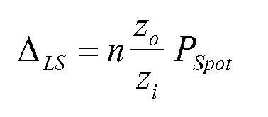
vorgegebenen Abstand ΔLS beabstandet sind,
wobei n eine Integer-Zahl 1, 2, 3, ..., darstellt, zi die optische Distanz zwischen dem der Lichtabgabeeinrichtung (6a) zugeordneten optischen Element (9a) und der Projektionsebene (3) darstellt, zo die optische Distanz zwischen der Lichtabgabeeinrichtung (6a) und dem optischen Element (9a) darstellt und Pspot den Projektions-Pitch darstellt. - Lichtabgabesystem (1) nach einem der vorangegangenen Ansprüche, wobei das optische System (7) weiterhin ein Strahlrichtelement umfasst, das zwischen dem Array von optischen Elementen (9a-c) und der Projektionsebene (3) angeordnet ist, wobei das Strahlrichtelement so eingerichtet ist, dass es von dem Array von optischen Elementen ausgehende Lichtstrahlen auf das projizierte Array von beleuchteten Spots (11a-c) in der Projektionsebene (3) richtet.
- Lichtabgabesystem (1) nach einem der vorangegangenen Ansprüche, wobei das optische System (7) weiterhin ein Strahlrichtelement umfasst, das zwischen dem Array (5) von Lichtabgabeeinrichtungen und dem Array von optischen Elementen (9a-c) angeordnet ist, wobei das Strahlrichtelement so eingerichtet ist, dass es von den Lichtabgabeeinrichtungen (6a-c) abgestrahlte Lichtstrahlen auf das projizierte Array von beleuchteten Spots (11a-c) in der Projektionsebene (3) richtet.
- Lichtabgabesystem (1) nach Anspruch 7 oder 8, wobei das Strahlrichtelement ein Array von richtenden optischen Elementen (17a-i) umfasst, wobei jedes so eingerichtet ist, dass es einen von einer zugeordneten Lichtabgabeeinrichtung (6a-c) in dem Array von Lichtabgabeeinrichtungen abgestrahlten Lichtstrahl auf einen zugeordneten Spot (11a-c) in dem projizierten Array von beleuchteten Spots in der Projektionsebene (3) richtet.
- Lichtabgabesystem (1) nach einem der vorangegangenen Ansprüche, das so eingerichtet ist, dass es eine relative Bewegung zwischen dem Array (5) von Lichtabgabeeinrichtungen (6a-c) und dem optischen System (7) ermöglicht.
- Lichtabgabesystem (1) nach Anspruch 10, das so eingerichtet ist, dass es die Einstellung einer Distanz (zo) zwischen dem Array (5) von Lichtabgabeeinrichtungen und dem optischen System (7) ermöglicht.
- Lichtabgabesystem (1) nach einem der vorangegangenen Ansprüche, das die Lichtabgabeeinrichtungen (6a-c) trennende Trennwände umfasst, wobei die Trennwände zwischen dem Array (5) von Lichtabgabeeinrichtungen und dem optischen System (7) angeordnet sind.
Priority Applications (1)
| Application Number | Priority Date | Filing Date | Title |
|---|---|---|---|
| EP10710674.2A EP2406540B1 (de) | 2009-03-13 | 2010-03-11 | Lichtausgabesystem zur projektion von mustern |
Applications Claiming Priority (3)
| Application Number | Priority Date | Filing Date | Title |
|---|---|---|---|
| EP09155156 | 2009-03-13 | ||
| EP10710674.2A EP2406540B1 (de) | 2009-03-13 | 2010-03-11 | Lichtausgabesystem zur projektion von mustern |
| PCT/IB2010/051047 WO2010103477A1 (en) | 2009-03-13 | 2010-03-11 | Pattern-projecting light-output system |
Publications (2)
| Publication Number | Publication Date |
|---|---|
| EP2406540A1 EP2406540A1 (de) | 2012-01-18 |
| EP2406540B1 true EP2406540B1 (de) | 2016-01-06 |
Family
ID=42244569
Family Applications (1)
| Application Number | Title | Priority Date | Filing Date |
|---|---|---|---|
| EP10710674.2A Active EP2406540B1 (de) | 2009-03-13 | 2010-03-11 | Lichtausgabesystem zur projektion von mustern |
Country Status (9)
| Country | Link |
|---|---|
| US (1) | US9404629B2 (de) |
| EP (1) | EP2406540B1 (de) |
| JP (1) | JP5918541B2 (de) |
| KR (1) | KR20110138374A (de) |
| CN (1) | CN102348929B (de) |
| BR (1) | BRPI1006354A2 (de) |
| RU (1) | RU2524403C2 (de) |
| TW (1) | TW201040447A (de) |
| WO (1) | WO2010103477A1 (de) |
Families Citing this family (24)
| Publication number | Priority date | Publication date | Assignee | Title |
|---|---|---|---|---|
| TW201040447A (en) * | 2009-03-13 | 2010-11-16 | Koninkl Philips Electronics Nv | Pattern-projecting light-output system |
| US8496354B2 (en) | 2010-11-24 | 2013-07-30 | Robe Lighting S.R.O. | Beam control system for an LED luminaire |
| US9033534B2 (en) * | 2011-04-20 | 2015-05-19 | Jasper Ridge Inc. | Hands-free vision aid |
| EP2718620B1 (de) * | 2011-06-10 | 2016-12-14 | Martin Professional A/S | Multimodale beleuchtungsvorrichtung |
| EP2718619B8 (de) * | 2011-06-10 | 2017-06-28 | Martin Professional ApS | Mechanische farbmischvorrichtung |
| WO2014030086A1 (en) * | 2012-08-24 | 2014-02-27 | Koninklijke Philips N.V. | A lighting device |
| US9423105B2 (en) | 2012-08-24 | 2016-08-23 | Koninklijke Philips N.V. | Lighting device having electrically switchable optical member |
| EP2959215A4 (de) * | 2013-02-25 | 2017-02-01 | Rensselaer Polytechnic Institute | Beleuchtung mit geringer luminanz |
| JP5920612B2 (ja) * | 2013-10-24 | 2016-05-18 | フィリップス ライティング ホールディング ビー ヴィ | 2つ以上のマイクロ構造化されたフィルムを有する光学構造 |
| US10156342B2 (en) * | 2013-11-25 | 2018-12-18 | Philips Lighting Holding B.V. | Lighting device with elastic envelope |
| US10533726B2 (en) | 2014-06-26 | 2020-01-14 | Signify Holding B.V. | Optical arrangement, lighting device and illumination method |
| US10222029B2 (en) | 2014-09-30 | 2019-03-05 | The Boeing Company | Array-based lighting systems and methods of manufacturing |
| DE102015112848A1 (de) * | 2015-08-05 | 2017-02-09 | Luke Roberts Gmbh | Verbesserte Raumleuchte |
| FR3049685B1 (fr) * | 2016-04-04 | 2020-05-08 | Ayrton | Projecteur comprenant un support et au moins un module lumineux pour produire un faisceau lumineux et un dispositif lumineux comprenant ledit projecteur |
| FR3049688B1 (fr) | 2016-04-04 | 2020-01-03 | Ayrton | Projecteur adapte pour un dispositif lumineux comprenant au moins un module lumineux avec une position reglable et un dispositif lumineux comprenant ledit projecteur |
| US10859235B2 (en) * | 2016-06-02 | 2020-12-08 | Federal Signal Corporation | Warning devices with oscillating light patterns |
| JP7002552B2 (ja) | 2017-01-17 | 2022-02-04 | シグニファイ ホールディング ビー ヴィ | 調節可能なスポットライト位置生成 |
| CN107121880B (zh) * | 2017-07-04 | 2022-10-18 | 宁波微阵光学技术有限公司 | 一种动态图像投影系统 |
| EP3781860B1 (de) | 2018-04-20 | 2025-03-19 | Beckman Coulter, Inc. | Projektion eines statusanzeigers |
| CN111338161B (zh) * | 2018-12-18 | 2022-04-12 | 深圳光峰科技股份有限公司 | 投影装置 |
| US11137128B2 (en) | 2019-04-01 | 2021-10-05 | Federal Signal Corporation | Warning devices with oscillating light patterns |
| CN110701561A (zh) * | 2019-10-14 | 2020-01-17 | 杭州行至云起科技有限公司 | 一种多功能灯具 |
| CN115342322A (zh) * | 2021-05-14 | 2022-11-15 | 广州光联电子科技有限公司 | 一种光源模式可调的光源系统 |
| SK10223Y1 (sk) * | 2024-02-26 | 2025-01-15 | Innova Projection, s.r.o. | Zariadenie a systém na projekciu a/alebo na osvetlenie, spôsob riadenia projekcie a/alebo osvetlenia |
Citations (1)
| Publication number | Priority date | Publication date | Assignee | Title |
|---|---|---|---|---|
| WO2010103477A1 (en) * | 2009-03-13 | 2010-09-16 | Koninklijke Philips Electronics N.V. | Pattern-projecting light-output system |
Family Cites Families (36)
| Publication number | Priority date | Publication date | Assignee | Title |
|---|---|---|---|---|
| US1880026A (en) * | 1931-01-02 | 1932-09-27 | Singerman Joseph | Color box |
| US4641446A (en) * | 1985-03-11 | 1987-02-10 | Jackson Thomas L | Apparatus and method for producing a multisided, multicolored display |
| DE4324849C2 (de) * | 1993-07-23 | 1995-07-13 | Schneider Rundfunkwerke Ag | Videosystem zum Erzeugen eines Farbvideobilds auf einem Schirm |
| US5722760A (en) * | 1995-02-03 | 1998-03-03 | Chien; Tseng Lu | Electro-luminescent light assembly |
| US5612821A (en) * | 1995-06-15 | 1997-03-18 | United Technologies Corporation | Micro lens system for controlling an optical beam pattern |
| JPH09211487A (ja) * | 1996-01-31 | 1997-08-15 | Dainippon Printing Co Ltd | 液晶表示方法及び液晶表示装置 |
| US6227669B1 (en) * | 1998-05-26 | 2001-05-08 | Industrial Technology Research Institute | Illumination device and image projection apparatus comprising the device |
| US6078371A (en) | 1998-10-05 | 2000-06-20 | Canon Kabushiki Kaisha | Liquid crystal device and liquid crystal display apparatus |
| RU2195694C2 (ru) * | 1998-10-16 | 2002-12-27 | Иванов Анатолий Геннадьевич | Способ формирования изображения, устройство для его осуществления и способ формирования видеосигнала |
| JP2000200052A (ja) | 1998-10-30 | 2000-07-18 | Toshiba Corp | 表示装置 |
| TW380213B (en) * | 1999-01-21 | 2000-01-21 | Ind Tech Res Inst | Illumination apparatus and image projection apparatus includes the same |
| DE19908040A1 (de) * | 1999-02-24 | 2000-08-31 | Diehl Stiftung & Co | Einrichtung zur Beleuchtung von Räumen, Körpern oder Flächen |
| TW457732B (en) * | 1999-08-27 | 2001-10-01 | Lumileds Lighting Bv | Luminaire, optical element and method of illuminating an object |
| US20020126479A1 (en) * | 2001-03-08 | 2002-09-12 | Ball Semiconductor, Inc. | High power incoherent light source with laser array |
| US6955449B2 (en) * | 2001-04-13 | 2005-10-18 | Gelcore Llc | LED symbol signal |
| RU2284605C2 (ru) * | 2002-02-07 | 2006-09-27 | РГБ Технолоджис АБ | Способ тестирования |
| JP2003330111A (ja) | 2002-05-10 | 2003-11-19 | Olympus Optical Co Ltd | 発光ユニット、照明装置、及び投影表示装置 |
| JP2004093623A (ja) * | 2002-08-29 | 2004-03-25 | Olympus Corp | 照明装置及びそれを用いた表示装置 |
| EP1422467A3 (de) * | 2002-11-22 | 2006-10-25 | Mellert SLT GmbH & Co. KG | Mobile Leuchte |
| JP4167570B2 (ja) * | 2003-09-11 | 2008-10-15 | 埼玉日本電気株式会社 | 携帯電子機器で用いられるイルミネーション構造、及び該構造を備える携帯電子機器 |
| US7430355B2 (en) * | 2003-12-08 | 2008-09-30 | University Of Cincinnati | Light emissive signage devices based on lightwave coupling |
| JP4437675B2 (ja) | 2003-12-26 | 2010-03-24 | 日本精機株式会社 | 照明装置 |
| CA2557447C (en) * | 2004-02-26 | 2012-12-18 | Tir Systems Ltd. | Apparatus for forming an asymmetric illumination beam pattern |
| JP4360945B2 (ja) * | 2004-03-10 | 2009-11-11 | シチズン電子株式会社 | 照明装置 |
| JP4488183B2 (ja) | 2004-03-30 | 2010-06-23 | Yanchers株式会社 | 照明装置 |
| JP2005352205A (ja) | 2004-06-10 | 2005-12-22 | Fujinon Corp | 照明装置 |
| WO2006033032A1 (en) * | 2004-09-24 | 2006-03-30 | Koninklijke Philips Electronics N.V. | Illumination system |
| US7281811B2 (en) | 2005-03-31 | 2007-10-16 | S. C. Johnson & Son, Inc. | Multi-clarity lenses |
| DE102005025135A1 (de) * | 2005-06-01 | 2006-12-07 | Robert Bosch Gmbh | Kraftstoffeinspritzventil für Brennkraftmaschinen |
| KR20080036195A (ko) * | 2005-07-13 | 2008-04-25 | 코닌클리즈케 필립스 일렉트로닉스 엔.브이. | 조명 시스템 |
| JP4799341B2 (ja) * | 2005-10-14 | 2011-10-26 | 株式会社東芝 | 照明装置 |
| TW200741134A (en) * | 2005-12-12 | 2007-11-01 | Koninkl Philips Electronics Nv | Optical device for creating an illumination window |
| JP2008103300A (ja) | 2006-09-21 | 2008-05-01 | Toshiba Lighting & Technology Corp | Ledモジュール及び照明器具 |
| CN201021765Y (zh) | 2007-03-26 | 2008-02-13 | 郑永发 | 发光二极管舞台投射灯 |
| WO2008142621A1 (en) | 2007-05-21 | 2008-11-27 | Philips Intellectual Property & Standards Gmbh | A light projecting device comprising an array of led's |
| US7931517B2 (en) * | 2009-02-25 | 2011-04-26 | Joe Yang | LED-based white-light lighting module for preventing glare and providing adjustable color temperature |
-
2010
- 2010-03-10 TW TW099106986A patent/TW201040447A/zh unknown
- 2010-03-11 JP JP2011553588A patent/JP5918541B2/ja active Active
- 2010-03-11 BR BRPI1006354A patent/BRPI1006354A2/pt not_active IP Right Cessation
- 2010-03-11 US US13/256,235 patent/US9404629B2/en active Active
- 2010-03-11 KR KR1020117023947A patent/KR20110138374A/ko not_active Abandoned
- 2010-03-11 RU RU2011141449/07A patent/RU2524403C2/ru not_active IP Right Cessation
- 2010-03-11 EP EP10710674.2A patent/EP2406540B1/de active Active
- 2010-03-11 WO PCT/IB2010/051047 patent/WO2010103477A1/en not_active Ceased
- 2010-03-11 CN CN2010800116192A patent/CN102348929B/zh active Active
Patent Citations (1)
| Publication number | Priority date | Publication date | Assignee | Title |
|---|---|---|---|---|
| WO2010103477A1 (en) * | 2009-03-13 | 2010-09-16 | Koninklijke Philips Electronics N.V. | Pattern-projecting light-output system |
Also Published As
| Publication number | Publication date |
|---|---|
| JP2012520482A (ja) | 2012-09-06 |
| TW201040447A (en) | 2010-11-16 |
| KR20110138374A (ko) | 2011-12-27 |
| CN102348929B (zh) | 2013-06-12 |
| WO2010103477A1 (en) | 2010-09-16 |
| CN102348929A (zh) | 2012-02-08 |
| EP2406540A1 (de) | 2012-01-18 |
| US9404629B2 (en) | 2016-08-02 |
| BRPI1006354A2 (pt) | 2016-02-10 |
| JP5918541B2 (ja) | 2016-05-18 |
| RU2524403C2 (ru) | 2014-07-27 |
| US20120092863A1 (en) | 2012-04-19 |
| RU2011141449A (ru) | 2013-04-20 |
Similar Documents
| Publication | Publication Date | Title |
|---|---|---|
| US9404629B2 (en) | Pattern-projecting light-output system | |
| KR102214346B1 (ko) | 회절성 멀티빔 소자 기반의 백라이팅 | |
| TWI639854B (zh) | 具有頭部追蹤功能的多視角顯示器、系統及方法 | |
| US9268078B2 (en) | Color-mixing convergent optical system | |
| US9291806B2 (en) | Beam pattern projector with modulating array of light sources | |
| JP6633087B2 (ja) | 3次元(3d)電子ディスプレイ | |
| KR20150030246A (ko) | 효율적인 공간 변조 조명 시스템 | |
| TW201736916A (zh) | 分時多工背光板、該背光板的操作方法以及使用該背光板的多視角顯示器 | |
| JP2018537698A (ja) | シフトマルチビーム回折格子を使用した角度サブピクセルレンダリングマルチビューディスプレイ | |
| JP2005352205A (ja) | 照明装置 | |
| TWI677738B (zh) | 多色靜態多視角顯示器及其操作方法 | |
| JP5403255B2 (ja) | 照明装置およびプロジェクター | |
| US11821608B2 (en) | Lighting device having light-transmissive cover layer between a lens array and a light source array | |
| CN118043727A (zh) | 静态彩色多视图显示器和方法 | |
| EP4108980A1 (de) | Lichtquellenvorrichtung und bildanzeigevorrichtung | |
| US10359692B2 (en) | Laser illumination system and method for eliminating laser speckle thereof | |
| CN210771529U (zh) | 拼接式面光源 | |
| RU2337386C2 (ru) | Способ формирования стереоизображений | |
| WO2013111032A1 (en) | Lighting system and a luminaire | |
| JP2024063918A (ja) | 照明装置及び照明アレイ装置 | |
| HK1254584A1 (en) | Multibeam diffraction grating-based display with head tracking | |
| HK40021864A (en) | Multicolor static multiview display and method | |
| HK40021864B (en) | Multicolor static multiview display and method |
Legal Events
| Date | Code | Title | Description |
|---|---|---|---|
| PUAI | Public reference made under article 153(3) epc to a published international application that has entered the european phase |
Free format text: ORIGINAL CODE: 0009012 |
|
| 17P | Request for examination filed |
Effective date: 20111013 |
|
| AK | Designated contracting states |
Kind code of ref document: A1 Designated state(s): AT BE BG CH CY CZ DE DK EE ES FI FR GB GR HR HU IE IS IT LI LT LU LV MC MK MT NL NO PL PT RO SE SI SK SM TR |
|
| DAX | Request for extension of the european patent (deleted) | ||
| RAP1 | Party data changed (applicant data changed or rights of an application transferred) |
Owner name: KONINKLIJKE PHILIPS N.V. |
|
| GRAP | Despatch of communication of intention to grant a patent |
Free format text: ORIGINAL CODE: EPIDOSNIGR1 |
|
| INTG | Intention to grant announced |
Effective date: 20150716 |
|
| GRAS | Grant fee paid |
Free format text: ORIGINAL CODE: EPIDOSNIGR3 |
|
| GRAA | (expected) grant |
Free format text: ORIGINAL CODE: 0009210 |
|
| AK | Designated contracting states |
Kind code of ref document: B1 Designated state(s): AT BE BG CH CY CZ DE DK EE ES FI FR GB GR HR HU IE IS IT LI LT LU LV MC MK MT NL NO PL PT RO SE SI SK SM TR |
|
| REG | Reference to a national code |
Ref country code: GB Ref legal event code: FG4D |
|
| REG | Reference to a national code |
Ref country code: CH Ref legal event code: EP |
|
| REG | Reference to a national code |
Ref country code: IE Ref legal event code: FG4D |
|
| REG | Reference to a national code |
Ref country code: AT Ref legal event code: REF Ref document number: 769158 Country of ref document: AT Kind code of ref document: T Effective date: 20160215 |
|
| REG | Reference to a national code |
Ref country code: DE Ref legal event code: R096 Ref document number: 602010029882 Country of ref document: DE |
|
| REG | Reference to a national code |
Ref country code: FR Ref legal event code: PLFP Year of fee payment: 7 |
|
| REG | Reference to a national code |
Ref country code: LT Ref legal event code: MG4D |
|
| REG | Reference to a national code |
Ref country code: NL Ref legal event code: MP Effective date: 20160106 |
|
| REG | Reference to a national code |
Ref country code: AT Ref legal event code: MK05 Ref document number: 769158 Country of ref document: AT Kind code of ref document: T Effective date: 20160106 |
|
| PG25 | Lapsed in a contracting state [announced via postgrant information from national office to epo] |
Ref country code: NL Free format text: LAPSE BECAUSE OF FAILURE TO SUBMIT A TRANSLATION OF THE DESCRIPTION OR TO PAY THE FEE WITHIN THE PRESCRIBED TIME-LIMIT Effective date: 20160106 |
|
| PG25 | Lapsed in a contracting state [announced via postgrant information from national office to epo] |
Ref country code: IT Free format text: LAPSE BECAUSE OF FAILURE TO SUBMIT A TRANSLATION OF THE DESCRIPTION OR TO PAY THE FEE WITHIN THE PRESCRIBED TIME-LIMIT Effective date: 20160106 Ref country code: ES Free format text: LAPSE BECAUSE OF FAILURE TO SUBMIT A TRANSLATION OF THE DESCRIPTION OR TO PAY THE FEE WITHIN THE PRESCRIBED TIME-LIMIT Effective date: 20160106 Ref country code: NO Free format text: LAPSE BECAUSE OF FAILURE TO SUBMIT A TRANSLATION OF THE DESCRIPTION OR TO PAY THE FEE WITHIN THE PRESCRIBED TIME-LIMIT Effective date: 20160406 Ref country code: HR Free format text: LAPSE BECAUSE OF FAILURE TO SUBMIT A TRANSLATION OF THE DESCRIPTION OR TO PAY THE FEE WITHIN THE PRESCRIBED TIME-LIMIT Effective date: 20160106 Ref country code: FI Free format text: LAPSE BECAUSE OF FAILURE TO SUBMIT A TRANSLATION OF THE DESCRIPTION OR TO PAY THE FEE WITHIN THE PRESCRIBED TIME-LIMIT Effective date: 20160106 Ref country code: GR Free format text: LAPSE BECAUSE OF FAILURE TO SUBMIT A TRANSLATION OF THE DESCRIPTION OR TO PAY THE FEE WITHIN THE PRESCRIBED TIME-LIMIT Effective date: 20160407 |
|
| PG25 | Lapsed in a contracting state [announced via postgrant information from national office to epo] |
Ref country code: SE Free format text: LAPSE BECAUSE OF FAILURE TO SUBMIT A TRANSLATION OF THE DESCRIPTION OR TO PAY THE FEE WITHIN THE PRESCRIBED TIME-LIMIT Effective date: 20160106 Ref country code: PT Free format text: LAPSE BECAUSE OF FAILURE TO SUBMIT A TRANSLATION OF THE DESCRIPTION OR TO PAY THE FEE WITHIN THE PRESCRIBED TIME-LIMIT Effective date: 20160506 Ref country code: LV Free format text: LAPSE BECAUSE OF FAILURE TO SUBMIT A TRANSLATION OF THE DESCRIPTION OR TO PAY THE FEE WITHIN THE PRESCRIBED TIME-LIMIT Effective date: 20160106 Ref country code: LT Free format text: LAPSE BECAUSE OF FAILURE TO SUBMIT A TRANSLATION OF THE DESCRIPTION OR TO PAY THE FEE WITHIN THE PRESCRIBED TIME-LIMIT Effective date: 20160106 Ref country code: PL Free format text: LAPSE BECAUSE OF FAILURE TO SUBMIT A TRANSLATION OF THE DESCRIPTION OR TO PAY THE FEE WITHIN THE PRESCRIBED TIME-LIMIT Effective date: 20160106 Ref country code: AT Free format text: LAPSE BECAUSE OF FAILURE TO SUBMIT A TRANSLATION OF THE DESCRIPTION OR TO PAY THE FEE WITHIN THE PRESCRIBED TIME-LIMIT Effective date: 20160106 Ref country code: IS Free format text: LAPSE BECAUSE OF FAILURE TO SUBMIT A TRANSLATION OF THE DESCRIPTION OR TO PAY THE FEE WITHIN THE PRESCRIBED TIME-LIMIT Effective date: 20160506 Ref country code: BE Free format text: LAPSE BECAUSE OF NON-PAYMENT OF DUE FEES Effective date: 20160331 |
|
| REG | Reference to a national code |
Ref country code: DE Ref legal event code: R097 Ref document number: 602010029882 Country of ref document: DE |
|
| PG25 | Lapsed in a contracting state [announced via postgrant information from national office to epo] |
Ref country code: EE Free format text: LAPSE BECAUSE OF FAILURE TO SUBMIT A TRANSLATION OF THE DESCRIPTION OR TO PAY THE FEE WITHIN THE PRESCRIBED TIME-LIMIT Effective date: 20160106 Ref country code: LU Free format text: LAPSE BECAUSE OF FAILURE TO SUBMIT A TRANSLATION OF THE DESCRIPTION OR TO PAY THE FEE WITHIN THE PRESCRIBED TIME-LIMIT Effective date: 20160311 Ref country code: DK Free format text: LAPSE BECAUSE OF FAILURE TO SUBMIT A TRANSLATION OF THE DESCRIPTION OR TO PAY THE FEE WITHIN THE PRESCRIBED TIME-LIMIT Effective date: 20160106 Ref country code: MC Free format text: LAPSE BECAUSE OF FAILURE TO SUBMIT A TRANSLATION OF THE DESCRIPTION OR TO PAY THE FEE WITHIN THE PRESCRIBED TIME-LIMIT Effective date: 20160106 |
|
| REG | Reference to a national code |
Ref country code: CH Ref legal event code: PL |
|
| REG | Reference to a national code |
Ref country code: GB Ref legal event code: 732E Free format text: REGISTERED BETWEEN 20161006 AND 20161012 |
|
| PLBE | No opposition filed within time limit |
Free format text: ORIGINAL CODE: 0009261 |
|
| STAA | Information on the status of an ep patent application or granted ep patent |
Free format text: STATUS: NO OPPOSITION FILED WITHIN TIME LIMIT |
|
| PG25 | Lapsed in a contracting state [announced via postgrant information from national office to epo] |
Ref country code: CZ Free format text: LAPSE BECAUSE OF FAILURE TO SUBMIT A TRANSLATION OF THE DESCRIPTION OR TO PAY THE FEE WITHIN THE PRESCRIBED TIME-LIMIT Effective date: 20160106 Ref country code: SK Free format text: LAPSE BECAUSE OF FAILURE TO SUBMIT A TRANSLATION OF THE DESCRIPTION OR TO PAY THE FEE WITHIN THE PRESCRIBED TIME-LIMIT Effective date: 20160106 Ref country code: SM Free format text: LAPSE BECAUSE OF FAILURE TO SUBMIT A TRANSLATION OF THE DESCRIPTION OR TO PAY THE FEE WITHIN THE PRESCRIBED TIME-LIMIT Effective date: 20160106 Ref country code: RO Free format text: LAPSE BECAUSE OF FAILURE TO SUBMIT A TRANSLATION OF THE DESCRIPTION OR TO PAY THE FEE WITHIN THE PRESCRIBED TIME-LIMIT Effective date: 20160106 |
|
| 26N | No opposition filed |
Effective date: 20161007 |
|
| REG | Reference to a national code |
Ref country code: IE Ref legal event code: MM4A |
|
| PG25 | Lapsed in a contracting state [announced via postgrant information from national office to epo] |
Ref country code: BE Free format text: LAPSE BECAUSE OF FAILURE TO SUBMIT A TRANSLATION OF THE DESCRIPTION OR TO PAY THE FEE WITHIN THE PRESCRIBED TIME-LIMIT Effective date: 20160106 |
|
| PG25 | Lapsed in a contracting state [announced via postgrant information from national office to epo] |
Ref country code: IE Free format text: LAPSE BECAUSE OF NON-PAYMENT OF DUE FEES Effective date: 20160311 Ref country code: LI Free format text: LAPSE BECAUSE OF NON-PAYMENT OF DUE FEES Effective date: 20160331 Ref country code: CH Free format text: LAPSE BECAUSE OF NON-PAYMENT OF DUE FEES Effective date: 20160331 |
|
| REG | Reference to a national code |
Ref country code: DE Ref legal event code: R081 Ref document number: 602010029882 Country of ref document: DE Owner name: SIGNIFY HOLDING B.V., NL Free format text: FORMER OWNER: KONINKLIJKE PHILIPS N.V., EINDHOVEN, NL Ref country code: DE Ref legal event code: R082 Ref document number: 602010029882 Country of ref document: DE Representative=s name: MEISSNER BOLTE PATENTANWAELTE RECHTSANWAELTE P, DE Ref country code: DE Ref legal event code: R081 Ref document number: 602010029882 Country of ref document: DE Owner name: PHILIPS LIGHTING HOLDING B.V., NL Free format text: FORMER OWNER: KONINKLIJKE PHILIPS N.V., EINDHOVEN, NL |
|
| PG25 | Lapsed in a contracting state [announced via postgrant information from national office to epo] |
Ref country code: SI Free format text: LAPSE BECAUSE OF FAILURE TO SUBMIT A TRANSLATION OF THE DESCRIPTION OR TO PAY THE FEE WITHIN THE PRESCRIBED TIME-LIMIT Effective date: 20160106 Ref country code: BG Free format text: LAPSE BECAUSE OF FAILURE TO SUBMIT A TRANSLATION OF THE DESCRIPTION OR TO PAY THE FEE WITHIN THE PRESCRIBED TIME-LIMIT Effective date: 20160406 |
|
| REG | Reference to a national code |
Ref country code: FR Ref legal event code: PLFP Year of fee payment: 8 |
|
| PG25 | Lapsed in a contracting state [announced via postgrant information from national office to epo] |
Ref country code: MT Free format text: LAPSE BECAUSE OF FAILURE TO SUBMIT A TRANSLATION OF THE DESCRIPTION OR TO PAY THE FEE WITHIN THE PRESCRIBED TIME-LIMIT Effective date: 20160106 |
|
| REG | Reference to a national code |
Ref country code: FR Ref legal event code: PLFP Year of fee payment: 9 |
|
| PG25 | Lapsed in a contracting state [announced via postgrant information from national office to epo] |
Ref country code: CY Free format text: LAPSE BECAUSE OF FAILURE TO SUBMIT A TRANSLATION OF THE DESCRIPTION OR TO PAY THE FEE WITHIN THE PRESCRIBED TIME-LIMIT Effective date: 20160106 Ref country code: HU Free format text: LAPSE BECAUSE OF FAILURE TO SUBMIT A TRANSLATION OF THE DESCRIPTION OR TO PAY THE FEE WITHIN THE PRESCRIBED TIME-LIMIT; INVALID AB INITIO Effective date: 20100311 |
|
| PG25 | Lapsed in a contracting state [announced via postgrant information from national office to epo] |
Ref country code: TR Free format text: LAPSE BECAUSE OF FAILURE TO SUBMIT A TRANSLATION OF THE DESCRIPTION OR TO PAY THE FEE WITHIN THE PRESCRIBED TIME-LIMIT Effective date: 20160106 Ref country code: MT Free format text: LAPSE BECAUSE OF FAILURE TO SUBMIT A TRANSLATION OF THE DESCRIPTION OR TO PAY THE FEE WITHIN THE PRESCRIBED TIME-LIMIT Effective date: 20160331 Ref country code: MK Free format text: LAPSE BECAUSE OF FAILURE TO SUBMIT A TRANSLATION OF THE DESCRIPTION OR TO PAY THE FEE WITHIN THE PRESCRIBED TIME-LIMIT Effective date: 20160106 |
|
| RIC2 | Information provided on ipc code assigned after grant |
Ipc: F21Y 101/02 20000101ALI20100928BHEP Ipc: F21V 5/00 20180101ALI20100928BHEP Ipc: G02F 1/1335 20060101ALI20100928BHEP Ipc: G02B 3/00 20060101ALI20100928BHEP Ipc: H04N 9/31 20060101ALI20100928BHEP Ipc: F21S 10/00 20060101AFI20100928BHEP |
|
| REG | Reference to a national code |
Ref country code: DE Ref legal event code: R082 Ref document number: 602010029882 Country of ref document: DE Representative=s name: MEISSNER BOLTE PATENTANWAELTE RECHTSANWAELTE P, DE Ref country code: DE Ref legal event code: R081 Ref document number: 602010029882 Country of ref document: DE Owner name: SIGNIFY HOLDING B.V., NL Free format text: FORMER OWNER: PHILIPS LIGHTING HOLDING B.V., EINDHOVEN, NL |
|
| P01 | Opt-out of the competence of the unified patent court (upc) registered |
Effective date: 20230421 |
|
| PGFP | Annual fee paid to national office [announced via postgrant information from national office to epo] |
Ref country code: DE Payment date: 20250528 Year of fee payment: 16 |
|
| PGFP | Annual fee paid to national office [announced via postgrant information from national office to epo] |
Ref country code: GB Payment date: 20260323 Year of fee payment: 17 |
|
| PGFP | Annual fee paid to national office [announced via postgrant information from national office to epo] |
Ref country code: FR Payment date: 20260323 Year of fee payment: 17 |