EP2406802B1 - Steuerschaltung für einen elektromagnetischen aktuator eines vakuumschalters - Google Patents
Steuerschaltung für einen elektromagnetischen aktuator eines vakuumschalters Download PDFInfo
- Publication number
- EP2406802B1 EP2406802B1 EP10709995.4A EP10709995A EP2406802B1 EP 2406802 B1 EP2406802 B1 EP 2406802B1 EP 10709995 A EP10709995 A EP 10709995A EP 2406802 B1 EP2406802 B1 EP 2406802B1
- Authority
- EP
- European Patent Office
- Prior art keywords
- circuit
- switch
- electromechanical switch
- transistor
- coil
- Prior art date
- Legal status (The legal status is an assumption and is not a legal conclusion. Google has not performed a legal analysis and makes no representation as to the accuracy of the status listed.)
- Not-in-force
Links
Images


Classifications
-
- H—ELECTRICITY
- H01—ELECTRIC ELEMENTS
- H01H—ELECTRIC SWITCHES; RELAYS; SELECTORS; EMERGENCY PROTECTIVE DEVICES
- H01H9/00—Details of switching devices, not covered by groups H01H1/00 - H01H7/00
- H01H9/54—Circuit arrangements not adapted to a particular application of the switching device and for which no provision exists elsewhere
- H01H9/548—Electromechanical and static switch connected in series
-
- H—ELECTRICITY
- H01—ELECTRIC ELEMENTS
- H01F—MAGNETS; INDUCTANCES; TRANSFORMERS; SELECTION OF MATERIALS FOR THEIR MAGNETIC PROPERTIES
- H01F7/00—Magnets
- H01F7/06—Electromagnets; Actuators including electromagnets
- H01F7/08—Electromagnets; Actuators including electromagnets with armatures
- H01F7/18—Circuit arrangements for obtaining desired operating characteristics, e.g. for slow operation, for sequential energisation of windings, for high-speed energisation of windings
- H01F7/1805—Circuit arrangements for holding the operation of electromagnets or for holding the armature in attracted position with reduced energising current
- H01F7/1816—Circuit arrangements for holding the operation of electromagnets or for holding the armature in attracted position with reduced energising current making use of an energy accumulator
-
- H—ELECTRICITY
- H01—ELECTRIC ELEMENTS
- H01H—ELECTRIC SWITCHES; RELAYS; SELECTORS; EMERGENCY PROTECTIVE DEVICES
- H01H33/00—High-tension or heavy-current switches with arc-extinguishing or arc-preventing means
- H01H33/02—Details
- H01H33/28—Power arrangements internal to the switch for operating the driving mechanism
- H01H33/38—Power arrangements internal to the switch for operating the driving mechanism using electromagnet
-
- H—ELECTRICITY
- H01—ELECTRIC ELEMENTS
- H01H—ELECTRIC SWITCHES; RELAYS; SELECTORS; EMERGENCY PROTECTIVE DEVICES
- H01H47/00—Circuit arrangements not adapted to a particular application of the relay and designed to obtain desired operating characteristics or to provide energising current
- H01H47/22—Circuit arrangements not adapted to a particular application of the relay and designed to obtain desired operating characteristics or to provide energising current for supplying energising current for relay coil
-
- H—ELECTRICITY
- H01—ELECTRIC ELEMENTS
- H01H—ELECTRIC SWITCHES; RELAYS; SELECTORS; EMERGENCY PROTECTIVE DEVICES
- H01H9/00—Details of switching devices, not covered by groups H01H1/00 - H01H7/00
- H01H9/54—Circuit arrangements not adapted to a particular application of the switching device and for which no provision exists elsewhere
- H01H9/547—Combinations of mechanical switches and static switches, the latter being controlled by the former
Definitions
- the present invention relates to a high voltage switchgear magnetic actuator circuit which contains at least one permanent magnet and, more particularly, a high voltage device magnetic actuator circuit for a vacuum bulb, as described in US Pat. DE-A-19979572 .
- a high voltage device magnetic actuator is used to turn on or turn off a high voltage device.
- the high voltage device is switched on by closing the actuator and switching off the actuator.
- a magnetic actuator generally comprises a closure coil used during closure and an opening coil used during opening.
- the closing and opening coils of the magnetic actuators have a galvanic isolation. Despite this isolation, there persists between these coils, a residual magnetic coupling which makes the presence of a voltage on a coil generates a voltage on the other coil. Thus, when closing a magnetic actuator, the voltage applied to the closing coil of the actuator generates a voltage on the opening coil due to the residual coupling between the coils. In the case where an opening quickly follows the closure (case, by for example, short-circuit closure) the voltage generated on the opening coil is then opposed to the voltage of the closing signal thereby increasing the opening current and / or the opening time.
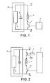
- the figure 1 represents, by way of example, a magnetic actuator circuit for a closed coil transistor vacuum interrupter of the prior art.
- the actuator circuit comprises a supply circuit A consisting, for example, of a charger 1 and a capacitor 2 connected in parallel with the charger 1, a coil 3, a transistor switch 4, a control circuit 5 of the switch transistor 4 and a permanent magnet (not shown in the figure).
- the permanent magnet locks the actuator core in the position corresponding to the closed state of the vacuum bulbs in the absence of current in the coil or coils of the actuator.
- the coil 3 and the transistor switch 4 are connected in series and form, between terminals P1 and P2, an assembly connected in parallel with the supply circuit A.
- the transistor switch 4 is, for example, a transistor which receives on its gate the switching control signal delivered by the circuit 5.
- the device controlled by closing by the actuator circuit is connected between the terminals P1 and P2 (this device is not shown in the figure).
- the accidental short-circuiting of the transistor causes the passage of a permanent current in the coil 3, which current induces a force of a few hundred to a few thousand Newtons.
- This force causes a displacement of the contacts of the vacuum bulb of a few millimeters. This displacement, even partial in the case where there is no touch contact, is not acceptable.
- the invention provides means capable of eliminating this disadvantage.
- a second electromechanical switch is mechanically connected to the first switch electromechanical so that it is the same command that controls the first electromechanical switch and the second electromechanical switch, the second electromechanical switch having a first terminal connected to a detection voltage and a second terminal connected to a voltage detection circuit.
- a signal shaping circuit is placed in series between the third electromechanical switch and the control input of the transistor switch in order to extend the duration of the control signal which is applied. on the control input of the transistor switch.
- a signal shaping circuit is placed in series between the fourth electromechanical switch and the control input of the first electromechanical switch to lengthen the duration of the control signal being applied. on the control input of the first electromechanical switch.
- a component mounted in parallel with the coil dissipates the energy released during the switching of the magnetic actuator circuit by limiting the overvoltages across the coil.
- the magnetic actuator circuit comprises two separate coils, of which a first coil is used for a switching on a high voltage device and a second coil is used to switch off the high voltage device.
- the coil is used for switching on or off a high voltage device.
- the magnetic actuator circuit of the invention has the advantage of avoiding any accidental operation of the device it controls. Because of the presence of the electromechanical switch in the actuator circuit, the current that is established in the apparatus under the action of the actuator circuit is established a little more slowly than in the prior art. This additional time of the establishment of the current is however not a disadvantage because it remains, in all cases, lower or even much lower, the closing time or opening of the device.
- the figure 2 represents a transistor actuator circuit of the invention provided with a closing coil.
- the actuator circuit of FIG. the invention comprises an electromechanical switch EM1 in series with the closing coil 3.
- the elements EM1, 3 and 4 are connected in series between the terminals P1 and P2.
- a coil b is placed, in a manner known per se, on the control circuit of the electromechanical switch EM1.
- the control signal of the electromechanical switch EM1 is delivered by the control circuit 5.
- the control circuit 5 is, for example, a microprocessor. In the idle state, the switches 4 and EM1 are in a blocked state (open circuit).
- a control signal is applied to the switch EM1 in order to close it (on state).
- a control signal is applied to the switch EM1 in order to close the latter, the switch EM1 being opened again as soon as the transistor switch 4 is placed again in open circuit.
- the mesh which gathers the electromechanical switch EM1 is advantageously in open circuit.
- a failure of the transistor control circuit 4 does not lead to any malfunction. No inadvertent operation of the apparatus controlled by the actuator circuit of the invention is then possible.
- the most common failure mode of an electromechanical switch is a permanent open state of the switch. As soon as a failure of the switch EM1 occurs, any control of the transistor switch 4 can no longer produce any effect and the apparatus which is controlled by the actuator circuit can also no longer be controlled. In this state of failure of the switch EM1, the apparatus which is controlled by the actuator circuit therefore advantageously continues to be protected from any inadvertent operation.
- the actuator circuit comprises a detection means which makes it possible to detect the state of closed switch (ie of glued relay) and this defect can then advantageously be signaled.
- the detection means is realized by an electromechanical switch EMd.
- the switch EMd has a first terminal connected to a detection voltage V 1 and a second terminal connected to a control input of the control circuit 5.
- the switch EMd is mechanically connected to the switch EM1 so that it is the same command that is applied to both switches.
- the EMd and EM1 switches are closed or opened simultaneously. It follows that when the switch EM1 is in closed mode "glued", the switch EMd is also closed and the voltage V 1 is detected by the control circuit.
- the actuator circuit then comprises an additional electromechanical switch and uses the control circuit. tripping which controls, in a manner known per se, the control circuit 5.
- the tripping circuit comprises a pulse generator 7 and an electromechanical switch EMb which has a first terminal connected to a control input of the control circuit 5 and a second terminal connected to a control voltage Vref. The pulses delivered by the generator 7 are applied to the control terminal of the switch EMb, thus making it possible to apply the control voltage Vref to the control input of the circuit 5.
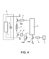
- the figure 4 represents an actuator circuit of the invention in which it is the control of the transistor switch which is sectioned.
- a third electromechanical switch EMa is placed in series between the switching circuit 5 and the control terminal of the transistor switch.
- the electromechanical switches EMa and EMb are mechanically connected so that it is the same control signal applied to them.
- a control pulse delivered by the pulse generator 7 simultaneously controls the EMa and EMb switches.
- the switch EMa is in open circuit and, advantageously, no control is applied to the transistor switch 4.
- the EMa switch closes and a control signal is applied to the transistor switch 4.
- the pulses delivered by the pulse generator have a duration generally shorter than the duration of the pulse to be applied to the coil of the actuator.
- a signal shaping circuit 6 is then placed in series between the control terminal of the transistor switch 4 and the switch EMa in order to extend the duration of the pulse which is applied to the transistor switch. For a pulse received with a duration substantially equal to 10 ms, the signal shaping circuit 6 then delivers, for example, a pulse of duration substantially equal to 100 ms which is a duration compatible with the duration of the pulses to be applied on the coil. of the actuator.
- Such a circuit advantageously avoids the circulation of an undesired current in the actuator coil.
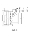
- FIG. 5 it is the control of the electromechanical switch EM1 which is cut off.
- An electromechanical switch EMc is here placed in series between the control circuit 5 and the control terminal of the electromechanical switch EM1.
- the elements EMc, EMb, 6 and 7 are used to prevent the flow of undesired current in the actuator coil.
- the figure 6 represents a third improvement of the transistor actuator circuit shown in FIG. figure 2 .
- a component 8 placed in parallel with the coil 3, for example a varistor, in which is dissipated the energy released during the switching of the actuator circuit. Overvoltages across the coil are limited to an acceptable value and the current flow time is not significantly changed.
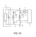
- the Figure 7A represents a first variant of a transistor actuator circuit of the invention provided with a closing coil and an opening coil.
- the circuit comprises a supply circuit A constituted, for example, by a charger 1 and a capacitor 2, a closing coil 9 series with an electromechanical switch EM2 and with a transistor switch 11, an opening coil 10 in series with an electromechanical switch EM3 and with a transistor switch 12, a control circuit 5 which delivers the control signals to the different switches and relay coils b.
- the series elements EM2, 9 and 11 constitute an assembly mounted between the terminals P1 and P2, in parallel with the assembly formed by the series elements EM3, 10 and 12.
- the switches EM2 and 11 control the opening of the device which is connected between the terminals P1 and P2 (not shown in the figure) and the switches EM1 and 12 controls the closing of this same device.
- the Figure 7B represents a second variant of a transistor actuator circuit of the invention provided with a closing coil and an opening coil.
- the closing coil 9 is connected in series between two electromechanical switches EM4 and EM5 and the opening coil 10 is connected in series between two electromechanical switches EM6 and EM7.
- the set of elements EM4, 9 and EM5 is connected in parallel with the set of elements EM6, 10 and EM7.
- the electromechanical switches EM4 and EM6 have a common terminal which is the P1 terminal and the electromechanical switches EM5 and EM7 have a common terminal which is a first terminal of a transistor switch 13 whose second terminal is the terminal P2.
- coils b are mounted on the control circuits of the various electromechanical switches. In the idle state, all switches (EM4, EM5, EM6, EM7, 13) are open (locked state).
- the electromechanical switches EM4 and EM5 are simultaneously closed (turned on) under the action of the controls applied to them shortly before the transistor switch 13 is turned off (turned on) and simultaneously opened (turned off) as soon as the transistor switch 13 is again placed in an open circuit .
- the electromechanical switches EM6 and EM7 are simultaneously closed (turned on) under the action of commands that are applied to them shortly before being closed (setting to the state) transistor switch 13 and simultaneously open (turned off) as soon as the transistor switch 13 is again placed in open circuit.
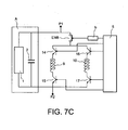
- the Figure 7C represents a third variant of a transistor actuator circuit of the invention provided with a closing coil and an opening coil.
- the closing coil 9 is connected in series between two transistor switches 14 and 15 and the opening coil 10 is connected in series between two transistor switches 16 and 17.
- the set of elements 14, 9 and 15 is connected in parallel with all of the elements 16, 10 and 17.
- the transistor switches 15 and 17 have a common terminal which is the terminal P2 and the transistor switches 14 and 16 have a common terminal which is a first terminal of an electromechanical switch EM8 whose second terminal is the terminal P1.
- coils b are mounted on the control circuits of the various electromechanical switches. In the idle state, all switches (14, 15, 16, 17, EM8) are open (off state).
- the electromechanical switch EM8 is closed (turned on) under the action of a command which is applied to it shortly before the transistor switches 14 and 15 are turned off simultaneously (turned on) and then turned on (turned off) when the transistor switches 14 and 15 are again simultaneously switched on. placed in open circuit.
- the electromechanical switch EM8 is closed (turned on) under the action of a command that is applied to it shortly before being closed. simultaneously (turning on) the transistor switches 16 and 17, and then open (turned off) as soon as the transistor switches 14 and 15 are again simultaneously placed in open circuit.
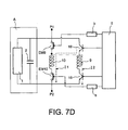
- the Figure 7D represents a fourth variant of a transistor actuator circuit of the invention provided with an opening coil and a closing coil.
- the opening coil 10 is connected in series between two electromechanical switches EM9 and EM10 and the closing coil 9 is connected in series between two transistor switches 18 and 19.
- a first terminal of the coil 9 is electrically connected to a first terminal of the coil 10, which first terminals are electrically connected to a first terminal of the electromechanical switch EM9 and to a first terminal of the transistor switch 18, the second terminals of the electromechanical switch EM9 and the transistor switch 18 being electrically connected to the terminal P1 .
- the second terminal of the coil 10 is electrically connected to a first terminal of electromechanical switch EM10 whose second terminal is electrically connected to the terminal P2 and the second terminal of the coil 9 is electrically connected to a first terminal of the transistor switch 19 whose second terminal is also connected to the terminal P2.
- all switches EM9, EM10, 18, 19
- the electromechanical switch EM10 is closed shortly before the transistor switch 18 is closed and then again open when the transistor switch 18 is placed in the open state. During this operation, switches EM9 and 19 remain in the open state. A current It travels the mesh formed by the elements 18, 10 and EM10 (see figure).
- the electromechanical switch EM9 is closed shortly before the transistor switch 19 is closed and then again opened as soon as the transistor switch 19 is placed in the open state. During this operation, switches EM10 and 18 remain in the open state. A stream 12 traverses the mesh formed by the elements EM9, 9, 19.
- FIGS 8A-8D will now be described which concern the different variants actuator of the invention in which a single coil is used, either for closing or for opening.
- the circuits represented on the Figures 8A-8D correspond, respectively, to the circuits represented on the Figures 7A-7D .
- Matching circuits it should be understood that, for the circuits concerned, the electromechanical and transistor switches are identical and are connected in the same way to the respective terminals P1 and P2.
- the figure 8A represents a first variant of a transistor actuator circuit of the invention provided with a single coil for opening and closing.
- This circuit corresponds to the circuit of the Figure 7A , which means that the switches EM2, EM3, 11 and 12 are connected to the terminals P1 and P2 as in the circuit of the Figure 7A .
- the switches EM2 and 11 are connected in series as well as the switches EM3 and 12.
- a first terminal of the single coil 20 is electrically connected to a common terminal which connects the switches EM2 and 11 and the second terminal of the single coil 20 is electrically connected to a common terminal which connects the switches EM3 and 12.
- the closing circuit then consists of the elements EM3, 20 and 11 and the opening circuit of the elements EM2, 20 and 12.
- c is the EM3 switch whose closing time frames the closing of the switch 11, the EM2 and 12 switches remaining open and, for the opening operation, it is the switch EM2 whose closure time frames that of the switch 12, the switches EM3 and 11 remaining open.
- the Figure 8B represents a second variant of a transistor actuator circuit of the invention provided with a single coil for opening and closing.
- the circuit of the Figure 8B corresponds to that of the Figure 7B . It comprises the electromechanical switches EM4, EM5, EM6 and EM7 and the transistor switch 13, which switches are connected to the respective terminals P1 and P2 in the same manner as in the circuit shown in FIG. Figure 7B .
- the single coil 20 has a first terminal connected to a common terminal of the EM4 and EM5 switches and a second terminal connected to a common terminal of the EM6 and EM7 switches.
- the closing circuit comprises the switch EM4, the coil 20, the switch EM7 and the switch 13 and the opening circuit comprises the switch EM6, the coil 20, the switch EM5 and the switch 13. For the closing operation, the EM4 and EM7 switches are closed while the EM5 and EM6 switches remain open and, for the opening operation, the EM5 and EM6 switches are closed while the EM4 and EM7 switches
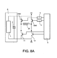
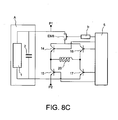
- the Figure 8C represents a third variant of a transistor actuator circuit of the invention provided with a single coil for opening and closing.
- the circuit of the Figure 8B corresponds to that of the Figure 7B . It comprises four transistor switches 14, 15, 16, 17 and an electromechanical switch EM8.
- the switches EM8, 14 and 16 are connected to the terminal P1 in the same way as in the circuit represented in FIG. Figure 7C .
- the switches 15 and 17 are connected to the terminal P2 in the same way as in the circuit represented in FIG. Figure 7C .
- the single coil 20 has a first terminal connected to a common terminal of the switches 14 and 15 and a second terminal connected to a common terminal of the switches 16 and 17.
- the closing circuit comprises the switch EM8, the switch 14, the coil 20 and the switch 17 and the opening circuit comprises the switch EM8, the switch 16, the coil 20 and the switch 15. It is the same electromechanical switch EM8 which closes for the closing operation and for the operation of opening.
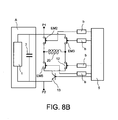
- the figure 8D represents a fourth variant of a transistor actuator circuit of the invention provided with a single coil for opening and closing.
- the circuit of the figure 8D corresponds to that of the Figure 7D . It comprises two electromechanical switches EM9, EM10 and two transistor switches 18 and 19.
- the switches EM9 and 18 are connected to the terminal P1 in the same way as in the circuit represented in FIG. Figure 7D .
- the switches EM10 and 19 are connected to the terminal P2 in the same way as in the circuit represented in FIG. Figure 7D .
- the closing circuit comprises the switch 18, the coil 20 and the switch EM10 and the opening circuit comprises the switch EM9, the coil 20 and the switch 19. For the closing operation, it is the switch EM10 which is closes, the EM9 switch remaining open and, for the opening operation, the opposite is the switch EM9 which closes, the EM10 switch remaining open.
Landscapes
- Keying Circuit Devices (AREA)
- Electronic Switches (AREA)
Claims (9)
- Magnetische Steuerschaltung für das Einschalten oder Ausschalten einer Hochspannungseinrichtung für Vakuumröhren, wobei die Steuerschaltung zumindest einen Dauermagneten und zumindest eine Spule (3) aufweist, die in Reihe mit einem Transistorschalter (4) geschaltet ist, der an einem Steueranschluss ein erstes Steuersignal empfängt, mit welchem der Transistorschalter in einen Durchlasszustand oder in einen Sperrzustand geschaltet wird,
dadurch gekennzeichnet, dass
sie einen ersten elektromechanischen Schalter (EM1) aufweist, der in Reihe mit dem Transistorschalter geschaltet ist und über ein zweites Steuersignal angesteuert wird, mit welchem der erste elektromechanische Schalter in einen Durchlasszustand oder einen Sperrzustand geschaltet wird, wobei der erste elektromechanische Schalter und der Transistorschalter standardmäßig in einem Sperrzustand vor jeglichem Einschalten oder Ausschalten der Hochspannungseinrichtung für Vakuumröhren ist, wobei das zweite Steuersignala) den elektromechanischen Schalter in einen Durchlasszustand zu einem Zeitpunkt schaltet, welcher dem Anlegen des ersten Steuersignals vorausgeht, mit dem der Transistorschalter in einen Durchlasszustand geschaltet wird, undb) den elektromechanischen Schalter wieder in einen Sperrzustand schaltet, sobald der Transistorschalter wieder in den Sperrzustand geschaltet ist. - Steuerschaltung nach Anspruch 1, wobei
ein zweiter elektromechanischer Schalter (EMd) mit dem ersten elektromechanischen Schalter (EM1) mechanisch so verbunden ist, dass der erste elektromechanische Schalter (EM1) und der zweite elektromechanische Schalter (EMd) mit dem gleichen Befehl angesteuert werden, wobei der zweite elektromechanische Schalter einen ersten Anschluss, an den eine Erfassungsspannung (V1) angelegt ist, sowie einen zweiten Anschluss aufweist, der mit einer Spannungserfassungsschaltung verbunden ist. - Steuerschaltung nach einem der Ansprüche 1 oder 2, wobei- ein dritter elektromechanischer Schalter (EMa) zwischen einem ersten Ausgangsanschluss eines Schaltkreises (5), welcher das erste Steuersignal ausgibt, und dem Steueranschluss des Transistorschalters (4) in Reihe geschaltet ist, und- ein elektromechanischer Schalter (EMb), der zu einem Auslöseschaltkreis (Emb, 7, Vref) gehört, welcher den Schaltkreis (5) ansteuert, mit dem dritten elektromechanischen Schalter (EMa) mechanisch so verbunden ist, dass der dritte elektromechanische Schalter und der elektromechanische Schalter (EMb), der zum Auslöseschaltkreis gehört, mit dem gleichen Steuersignal angesteuert werden.
- Steuerschaltung nach Anspruch 3, wobei
eine Signalaufbereitungsschaltung (6) zwischen dem dritten elektromechanischen Schalter und dem Steuereingang des Transistorschalters in Reihe geschaltet ist, um die Dauer des Steuersignals zu verlängern, das an den Steuereingang des Transistorschalters angelegt ist. - Steuerschaltung nach einem der Ansprüche 1 oder 2, wobei- ein vierter elektromechanischer Schalter (EMc) zwischen einem zweiten Ausgangsanschluss eines Schaltkreises (5), welcher das zweite Steuersignal ausgibt, und dem Steueranschluss des ersten elektromechanischen Schalters (EM1) in Reihe geschaltet ist, und- ein elektromechanischer Schalter (EMb), der zu einem Auslöseschaltkreis (Emb, 7, Vref) gehört, welcher den Schaltkreis (5) ansteuert, mit dem vierten elektromechanischen Schalter (EMc) mechanisch so verbunden ist, dass der vierte elektromechanische Schalter (EMc) und der elektromechanische Schalter (EMb), der zum Auslöseschaltkreis gehört, mit dem gleichen Steuersignal angesteuert werden.
- Steuerschaltung nach Anspruch 5, wobei
eine Signalaufbereitungsschaltung (6) zwischen dem vierten elektromechanischen Schalter und dem Steuereingang des ersten elektromechanischen Schalters in Reihe geschaltet ist, um die Dauer des Steuersignals zu verlängern, das an den Steuereingang des ersten elektromechanischen Schalters angelegt ist. - Steuerschaltung nach einem der vorangehenden Ansprüche, wobei
ein mit der Spule (3) parallel geschaltetes Bauteil (8) die während der Schaltvorgänge der magnetischen Steuerschaltung freigesetzte Energie dissipiert und dabei Überspannungen an den Anschlüssen der Spule begrenzt. - Steuerschaltung nach einem der vorangehenden Ansprüche,
dadurch gekennzeichnet, dass sie zwei verschiedene Spulen aufweist, wovon eine erste Spule (9) zum Einschalten eines Hochspannungsgeräts verwendet wird und eine zweite Spule (10) zum Ausschalten des Hochspannungsgeräts verwendet wird. - Steuerschaltung nach einem der Ansprüche 1 bis 7, wobei
die Spule (20) zum Einschalten oder zum Ausschalten eines Mittel- und/oder Hochspannungsgeräts verwendet wird.
Applications Claiming Priority (2)
| Application Number | Priority Date | Filing Date | Title |
|---|---|---|---|
| FR0951492A FR2943170B1 (fr) | 2009-03-10 | 2009-03-10 | Circuit actionneur magnetique |
| PCT/EP2010/052949 WO2010102989A1 (fr) | 2009-03-10 | 2010-03-09 | Circuit de commande d'un actionneur électromagnétique pour un interrupteur à vide |
Publications (2)
| Publication Number | Publication Date |
|---|---|
| EP2406802A1 EP2406802A1 (de) | 2012-01-18 |
| EP2406802B1 true EP2406802B1 (de) | 2014-11-12 |
Family
ID=41061269
Family Applications (1)
| Application Number | Title | Priority Date | Filing Date |
|---|---|---|---|
| EP10709995.4A Not-in-force EP2406802B1 (de) | 2009-03-10 | 2010-03-09 | Steuerschaltung für einen elektromagnetischen aktuator eines vakuumschalters |
Country Status (7)
| Country | Link |
|---|---|
| US (1) | US8569645B2 (de) |
| EP (1) | EP2406802B1 (de) |
| CN (1) | CN102414766B (de) |
| AU (1) | AU2010223361B2 (de) |
| ES (1) | ES2526250T3 (de) |
| FR (1) | FR2943170B1 (de) |
| WO (1) | WO2010102989A1 (de) |
Families Citing this family (14)
| Publication number | Priority date | Publication date | Assignee | Title |
|---|---|---|---|---|
| US20130182479A1 (en) * | 2012-01-17 | 2013-07-18 | Hamilton Sundstrand Corporation | Variable voltage reference in power rectification |
| US9343216B2 (en) * | 2013-09-02 | 2016-05-17 | Glen A. Robertson | Energy efficient bi-stable permanent magnet actuation system |
| CN103916080B (zh) * | 2014-04-17 | 2017-01-25 | 西北工业大学 | 小面积高线性度成形电路 |
| US20150332883A1 (en) * | 2014-05-14 | 2015-11-19 | Eaton Corporation | Electrical switching apparatus and linear actuator assembly therefor |
| FR3023648B1 (fr) | 2014-07-09 | 2016-07-01 | Schneider Electric Ind Sas | Dispositif d'arret d'urgence |
| EP3051568B1 (de) * | 2015-01-30 | 2019-03-13 | General Electric Technology GmbH | Betätigungsvorrichtung zum Auslösen eines Spannungsschutzschalters |
| CN105470041A (zh) * | 2015-12-16 | 2016-04-06 | 国网浙江省电力公司电力科学研究院 | 快速高压开关 |
| CN109690718B (zh) * | 2016-08-26 | 2020-04-24 | 三菱电机株式会社 | 电磁操作机构的驱动电路 |
| US11427105B2 (en) | 2016-10-25 | 2022-08-30 | Cps Technology Holdings Llc | Battery module parallel switching device systems and methods |
| CN106409607B (zh) * | 2016-11-30 | 2018-09-25 | 滁州学院 | 继电器简单快速切换型的永磁断路器分合闸智能控制模块 |
| JP7595338B2 (ja) * | 2019-11-11 | 2024-12-06 | 国立大学法人 東京大学 | 磁場発生装置 |
| JP2021082752A (ja) * | 2019-11-21 | 2021-05-27 | 豊興工業株式会社 | ソレノイド駆動回路 |
| WO2023283455A1 (en) * | 2021-07-08 | 2023-01-12 | Astronics Advanced Electronic Systems Corp. | Method and apparatus for handling contactor/relay contact bounce under transient conditions |
| US12387894B2 (en) | 2021-07-08 | 2025-08-12 | Astronics Advanced Electronic Systems Corp. | Method and apparatus for handling contactor / relay contact bounce under transient conditions |
Family Cites Families (12)
| Publication number | Priority date | Publication date | Assignee | Title |
|---|---|---|---|---|
| US3790862A (en) * | 1972-12-21 | 1974-02-05 | Square D Co | Excitation control circuit for electromagnet coil |
| US4860157A (en) * | 1988-04-25 | 1989-08-22 | General Electric Company | Molded case circuit breaker actuator-accessory module |
| DE4034485A1 (de) * | 1990-10-30 | 1992-05-07 | Ernst H Grundmann | Niederspannungsschaltgeraet |
| US5375027A (en) * | 1992-09-29 | 1994-12-20 | General Dynamics Corporation | Fail safe cartridge fire unit |
| DE29614718U1 (de) * | 1996-08-13 | 1996-10-17 | Siemens AG, 80333 München | Auslöser |
| DE19734589B4 (de) * | 1997-04-13 | 2005-12-08 | Elan Schaltelemente Gmbh & Co. Kg | Elektronischer Sicherheitsbaustein |
| US6013889A (en) * | 1997-06-02 | 2000-01-11 | Allen-Bradley Company, Llc | Method for retaining a movable contact in a circuit interrupter |
| DE19731269B4 (de) * | 1997-07-22 | 2006-02-23 | Hager Electro Gmbh | Vorrichtung zum Schalten von elektrischen Kontakten |
| DE19929572A1 (de) | 1999-06-22 | 2001-01-04 | Siemens Ag | Magnetischer Linearantrieb |
| JP4284876B2 (ja) * | 2001-03-13 | 2009-06-24 | パナソニック株式会社 | 電気床暖房装置 |
| US7715168B2 (en) * | 2006-05-08 | 2010-05-11 | Asco Power Technologies Lp | Controlled solenoid drive circuit |
| US7804038B2 (en) * | 2007-09-28 | 2010-09-28 | Rockwell Automation Technologies, Inc. | Multi-vacuum contactor control system |
-
2009
- 2009-03-10 FR FR0951492A patent/FR2943170B1/fr not_active Expired - Fee Related
-
2010
- 2010-03-09 AU AU2010223361A patent/AU2010223361B2/en not_active Ceased
- 2010-03-09 ES ES10709995.4T patent/ES2526250T3/es active Active
- 2010-03-09 EP EP10709995.4A patent/EP2406802B1/de not_active Not-in-force
- 2010-03-09 CN CN201080019436.5A patent/CN102414766B/zh not_active Expired - Fee Related
- 2010-03-09 US US13/254,673 patent/US8569645B2/en not_active Expired - Fee Related
- 2010-03-09 WO PCT/EP2010/052949 patent/WO2010102989A1/fr not_active Ceased
Also Published As
| Publication number | Publication date |
|---|---|
| ES2526250T3 (es) | 2015-01-08 |
| WO2010102989A1 (fr) | 2010-09-16 |
| EP2406802A1 (de) | 2012-01-18 |
| FR2943170B1 (fr) | 2013-03-22 |
| CN102414766A (zh) | 2012-04-11 |
| AU2010223361B2 (en) | 2014-09-04 |
| US8569645B2 (en) | 2013-10-29 |
| AU2010223361A1 (en) | 2011-10-13 |
| US20110315663A1 (en) | 2011-12-29 |
| CN102414766B (zh) | 2014-10-22 |
| FR2943170A1 (fr) | 2010-09-17 |
Similar Documents
| Publication | Publication Date | Title |
|---|---|---|
| EP2406802B1 (de) | Steuerschaltung für einen elektromagnetischen aktuator eines vakuumschalters | |
| EP3459100B1 (de) | Schaltervorrichtung zur verbindung mit einem elektrischen stromkreis | |
| FR2738664A1 (fr) | Dispositif hybride utilisant l'effet miller pour la protection des contacts electriques contre la formation d'arcs | |
| FR2853132A1 (fr) | Circuit de fonctionnement et dispositif de commutation de puissance utilisant un tel circuit. | |
| EP4167261A1 (de) | Elektrische schaltvorrichtung, entsprechendes schaltsystem und verfahren | |
| EP0204624B1 (de) | Einrichtung zur Überwachung des Zustands eines elektrischen Schalters und Anwendung in einem elektrischen Relais | |
| EP3437115B1 (de) | Hybridisierungsystem für hochspannungsgleichstrom | |
| EP4016570A1 (de) | Elektromechanische schaltvorrichtung einer elektrischen leistungsschaltung | |
| EP2842151B1 (de) | Aktuatorsschaltkreis für lastschalter | |
| EP2192605A1 (de) | Trennvorrichtung eines elektrischen Schaltkreises und Stromverteilungskasten, der mit einer solchen Trennvorrichtung ausgestattet ist | |
| FR2870986A1 (fr) | Dispositif de commande de relais pour appareil electrique en courant continu | |
| EP0780861B1 (de) | Elektrisches Gerät mit Bogenkommutierung | |
| EP3291271A1 (de) | Steuerungsverfahren einer betätigungsvorrichtung und entsprechende betätigungsvorrichtung und schaltvorrichtung | |
| FR2997196A1 (fr) | Circuit de test de disjoncteur haute tension a courant continu | |
| EP3699942A1 (de) | Einschaltsystem einer vakuumlampe | |
| EP2555216B1 (de) | Elektrogerät, das mit zwei Steuerklemmen ausgestattet ist, um ein mobiles Organ wahlweise in Ruhe- oder Arbeitsstellung zu versetzen | |
| FR3036222A1 (fr) | Procede de commande d'un changement d'etat de fonctionnement d'un organe electromecanique, par exemple un relais, et dispositif correspondant | |
| CH623276A5 (de) | ||
| EP4118670B1 (de) | Hybridschalter und steuergerät | |
| EP0834975A1 (de) | Elektrisches Verteilungsanschlusselement mit hybridem Begrenzerblock | |
| EP4139946B1 (de) | Leitungsschutzschalter mit elektronischer auslösesteuerung | |
| EP3894278B1 (de) | Vorrichtung zum vorladen eines stromnetzes | |
| CA3060084C (fr) | Systeme d'hybridation pour courant continu haute tension | |
| EP1628378B1 (de) | Überspannungsschutzvorrichtung einschliesslich paralleler Funkenstrecken | |
| WO2005001868A1 (fr) | Appareil electrique interrupteur a plusieurs actionneurs. |
Legal Events
| Date | Code | Title | Description |
|---|---|---|---|
| PUAI | Public reference made under article 153(3) epc to a published international application that has entered the european phase |
Free format text: ORIGINAL CODE: 0009012 |
|
| 17P | Request for examination filed |
Effective date: 20110909 |
|
| AK | Designated contracting states |
Kind code of ref document: A1 Designated state(s): AT BE BG CH CY CZ DE DK EE ES FI FR GB GR HR HU IE IS IT LI LT LU LV MC MK MT NL NO PL PT RO SE SI SK SM TR |
|
| DAX | Request for extension of the european patent (deleted) | ||
| GRAP | Despatch of communication of intention to grant a patent |
Free format text: ORIGINAL CODE: EPIDOSNIGR1 |
|
| INTG | Intention to grant announced |
Effective date: 20140604 |
|
| GRAS | Grant fee paid |
Free format text: ORIGINAL CODE: EPIDOSNIGR3 |
|
| GRAA | (expected) grant |
Free format text: ORIGINAL CODE: 0009210 |
|
| AK | Designated contracting states |
Kind code of ref document: B1 Designated state(s): AT BE BG CH CY CZ DE DK EE ES FI FR GB GR HR HU IE IS IT LI LT LU LV MC MK MT NL NO PL PT RO SE SI SK SM TR |
|
| REG | Reference to a national code |
Ref country code: GB Ref legal event code: FG4D Free format text: NOT ENGLISH |
|
| REG | Reference to a national code |
Ref country code: CH Ref legal event code: EP |
|
| REG | Reference to a national code |
Ref country code: AT Ref legal event code: REF Ref document number: 696191 Country of ref document: AT Kind code of ref document: T Effective date: 20141115 |
|
| REG | Reference to a national code |
Ref country code: IE Ref legal event code: FG4D Free format text: LANGUAGE OF EP DOCUMENT: FRENCH |
|
| REG | Reference to a national code |
Ref country code: DE Ref legal event code: R096 Ref document number: 602010020119 Country of ref document: DE Effective date: 20141224 |
|
| REG | Reference to a national code |
Ref country code: ES Ref legal event code: FG2A Ref document number: 2526250 Country of ref document: ES Kind code of ref document: T3 Effective date: 20150108 |
|
| REG | Reference to a national code |
Ref country code: NL Ref legal event code: VDEP Effective date: 20141112 |
|
| REG | Reference to a national code |
Ref country code: AT Ref legal event code: MK05 Ref document number: 696191 Country of ref document: AT Kind code of ref document: T Effective date: 20141112 |
|
| PG25 | Lapsed in a contracting state [announced via postgrant information from national office to epo] |
Ref country code: NL Free format text: LAPSE BECAUSE OF FAILURE TO SUBMIT A TRANSLATION OF THE DESCRIPTION OR TO PAY THE FEE WITHIN THE PRESCRIBED TIME-LIMIT Effective date: 20141112 Ref country code: PT Free format text: LAPSE BECAUSE OF FAILURE TO SUBMIT A TRANSLATION OF THE DESCRIPTION OR TO PAY THE FEE WITHIN THE PRESCRIBED TIME-LIMIT Effective date: 20150312 Ref country code: FI Free format text: LAPSE BECAUSE OF FAILURE TO SUBMIT A TRANSLATION OF THE DESCRIPTION OR TO PAY THE FEE WITHIN THE PRESCRIBED TIME-LIMIT Effective date: 20141112 Ref country code: IS Free format text: LAPSE BECAUSE OF FAILURE TO SUBMIT A TRANSLATION OF THE DESCRIPTION OR TO PAY THE FEE WITHIN THE PRESCRIBED TIME-LIMIT Effective date: 20150312 Ref country code: NO Free format text: LAPSE BECAUSE OF FAILURE TO SUBMIT A TRANSLATION OF THE DESCRIPTION OR TO PAY THE FEE WITHIN THE PRESCRIBED TIME-LIMIT Effective date: 20150212 Ref country code: LT Free format text: LAPSE BECAUSE OF FAILURE TO SUBMIT A TRANSLATION OF THE DESCRIPTION OR TO PAY THE FEE WITHIN THE PRESCRIBED TIME-LIMIT Effective date: 20141112 |
|
| PG25 | Lapsed in a contracting state [announced via postgrant information from national office to epo] |
Ref country code: LV Free format text: LAPSE BECAUSE OF FAILURE TO SUBMIT A TRANSLATION OF THE DESCRIPTION OR TO PAY THE FEE WITHIN THE PRESCRIBED TIME-LIMIT Effective date: 20141112 Ref country code: PL Free format text: LAPSE BECAUSE OF FAILURE TO SUBMIT A TRANSLATION OF THE DESCRIPTION OR TO PAY THE FEE WITHIN THE PRESCRIBED TIME-LIMIT Effective date: 20141112 Ref country code: SE Free format text: LAPSE BECAUSE OF FAILURE TO SUBMIT A TRANSLATION OF THE DESCRIPTION OR TO PAY THE FEE WITHIN THE PRESCRIBED TIME-LIMIT Effective date: 20141112 Ref country code: GR Free format text: LAPSE BECAUSE OF FAILURE TO SUBMIT A TRANSLATION OF THE DESCRIPTION OR TO PAY THE FEE WITHIN THE PRESCRIBED TIME-LIMIT Effective date: 20150213 Ref country code: AT Free format text: LAPSE BECAUSE OF FAILURE TO SUBMIT A TRANSLATION OF THE DESCRIPTION OR TO PAY THE FEE WITHIN THE PRESCRIBED TIME-LIMIT Effective date: 20141112 Ref country code: HR Free format text: LAPSE BECAUSE OF FAILURE TO SUBMIT A TRANSLATION OF THE DESCRIPTION OR TO PAY THE FEE WITHIN THE PRESCRIBED TIME-LIMIT Effective date: 20141112 Ref country code: CY Free format text: LAPSE BECAUSE OF FAILURE TO SUBMIT A TRANSLATION OF THE DESCRIPTION OR TO PAY THE FEE WITHIN THE PRESCRIBED TIME-LIMIT Effective date: 20141112 |
|
| PG25 | Lapsed in a contracting state [announced via postgrant information from national office to epo] |
Ref country code: SK Free format text: LAPSE BECAUSE OF FAILURE TO SUBMIT A TRANSLATION OF THE DESCRIPTION OR TO PAY THE FEE WITHIN THE PRESCRIBED TIME-LIMIT Effective date: 20141112 Ref country code: DK Free format text: LAPSE BECAUSE OF FAILURE TO SUBMIT A TRANSLATION OF THE DESCRIPTION OR TO PAY THE FEE WITHIN THE PRESCRIBED TIME-LIMIT Effective date: 20141112 Ref country code: EE Free format text: LAPSE BECAUSE OF FAILURE TO SUBMIT A TRANSLATION OF THE DESCRIPTION OR TO PAY THE FEE WITHIN THE PRESCRIBED TIME-LIMIT Effective date: 20141112 Ref country code: CZ Free format text: LAPSE BECAUSE OF FAILURE TO SUBMIT A TRANSLATION OF THE DESCRIPTION OR TO PAY THE FEE WITHIN THE PRESCRIBED TIME-LIMIT Effective date: 20141112 Ref country code: RO Free format text: LAPSE BECAUSE OF FAILURE TO SUBMIT A TRANSLATION OF THE DESCRIPTION OR TO PAY THE FEE WITHIN THE PRESCRIBED TIME-LIMIT Effective date: 20141112 |
|
| REG | Reference to a national code |
Ref country code: DE Ref legal event code: R097 Ref document number: 602010020119 Country of ref document: DE |
|
| PLBE | No opposition filed within time limit |
Free format text: ORIGINAL CODE: 0009261 |
|
| 26N | No opposition filed |
Effective date: 20150813 |
|
| PG25 | Lapsed in a contracting state [announced via postgrant information from national office to epo] |
Ref country code: MC Free format text: LAPSE BECAUSE OF FAILURE TO SUBMIT A TRANSLATION OF THE DESCRIPTION OR TO PAY THE FEE WITHIN THE PRESCRIBED TIME-LIMIT Effective date: 20141112 Ref country code: LU Free format text: LAPSE BECAUSE OF FAILURE TO SUBMIT A TRANSLATION OF THE DESCRIPTION OR TO PAY THE FEE WITHIN THE PRESCRIBED TIME-LIMIT Effective date: 20150309 |
|
| REG | Reference to a national code |
Ref country code: CH Ref legal event code: PL |
|
| REG | Reference to a national code |
Ref country code: IE Ref legal event code: MM4A |
|
| PG25 | Lapsed in a contracting state [announced via postgrant information from national office to epo] |
Ref country code: LI Free format text: LAPSE BECAUSE OF NON-PAYMENT OF DUE FEES Effective date: 20150331 Ref country code: CH Free format text: LAPSE BECAUSE OF NON-PAYMENT OF DUE FEES Effective date: 20150331 Ref country code: IE Free format text: LAPSE BECAUSE OF NON-PAYMENT OF DUE FEES Effective date: 20150309 |
|
| PG25 | Lapsed in a contracting state [announced via postgrant information from national office to epo] |
Ref country code: SI Free format text: LAPSE BECAUSE OF FAILURE TO SUBMIT A TRANSLATION OF THE DESCRIPTION OR TO PAY THE FEE WITHIN THE PRESCRIBED TIME-LIMIT Effective date: 20141112 |
|
| REG | Reference to a national code |
Ref country code: FR Ref legal event code: PLFP Year of fee payment: 7 |
|
| PGFP | Annual fee paid to national office [announced via postgrant information from national office to epo] |
Ref country code: DE Payment date: 20160310 Year of fee payment: 7 |
|
| PGFP | Annual fee paid to national office [announced via postgrant information from national office to epo] |
Ref country code: FR Payment date: 20160308 Year of fee payment: 7 Ref country code: GB Payment date: 20160309 Year of fee payment: 7 |
|
| PGFP | Annual fee paid to national office [announced via postgrant information from national office to epo] |
Ref country code: IT Payment date: 20160324 Year of fee payment: 7 |
|
| PG25 | Lapsed in a contracting state [announced via postgrant information from national office to epo] |
Ref country code: MT Free format text: LAPSE BECAUSE OF FAILURE TO SUBMIT A TRANSLATION OF THE DESCRIPTION OR TO PAY THE FEE WITHIN THE PRESCRIBED TIME-LIMIT Effective date: 20141112 |
|
| PG25 | Lapsed in a contracting state [announced via postgrant information from national office to epo] |
Ref country code: BG Free format text: LAPSE BECAUSE OF FAILURE TO SUBMIT A TRANSLATION OF THE DESCRIPTION OR TO PAY THE FEE WITHIN THE PRESCRIBED TIME-LIMIT Effective date: 20141112 Ref country code: HU Free format text: LAPSE BECAUSE OF FAILURE TO SUBMIT A TRANSLATION OF THE DESCRIPTION OR TO PAY THE FEE WITHIN THE PRESCRIBED TIME-LIMIT; INVALID AB INITIO Effective date: 20100309 Ref country code: SM Free format text: LAPSE BECAUSE OF FAILURE TO SUBMIT A TRANSLATION OF THE DESCRIPTION OR TO PAY THE FEE WITHIN THE PRESCRIBED TIME-LIMIT Effective date: 20141112 |
|
| PGFP | Annual fee paid to national office [announced via postgrant information from national office to epo] |
Ref country code: ES Payment date: 20170214 Year of fee payment: 8 |
|
| PG25 | Lapsed in a contracting state [announced via postgrant information from national office to epo] |
Ref country code: BE Free format text: LAPSE BECAUSE OF NON-PAYMENT OF DUE FEES Effective date: 20150331 |
|
| PG25 | Lapsed in a contracting state [announced via postgrant information from national office to epo] |
Ref country code: TR Free format text: LAPSE BECAUSE OF FAILURE TO SUBMIT A TRANSLATION OF THE DESCRIPTION OR TO PAY THE FEE WITHIN THE PRESCRIBED TIME-LIMIT Effective date: 20141112 |
|
| REG | Reference to a national code |
Ref country code: DE Ref legal event code: R119 Ref document number: 602010020119 Country of ref document: DE |
|
| GBPC | Gb: european patent ceased through non-payment of renewal fee |
Effective date: 20170309 |
|
| REG | Reference to a national code |
Ref country code: FR Ref legal event code: ST Effective date: 20171130 |
|
| PG25 | Lapsed in a contracting state [announced via postgrant information from national office to epo] |
Ref country code: FR Free format text: LAPSE BECAUSE OF NON-PAYMENT OF DUE FEES Effective date: 20170331 Ref country code: DE Free format text: LAPSE BECAUSE OF NON-PAYMENT OF DUE FEES Effective date: 20171003 |
|
| PG25 | Lapsed in a contracting state [announced via postgrant information from national office to epo] |
Ref country code: IT Free format text: LAPSE BECAUSE OF NON-PAYMENT OF DUE FEES Effective date: 20170309 Ref country code: GB Free format text: LAPSE BECAUSE OF NON-PAYMENT OF DUE FEES Effective date: 20170309 |
|
| PG25 | Lapsed in a contracting state [announced via postgrant information from national office to epo] |
Ref country code: MK Free format text: LAPSE BECAUSE OF FAILURE TO SUBMIT A TRANSLATION OF THE DESCRIPTION OR TO PAY THE FEE WITHIN THE PRESCRIBED TIME-LIMIT Effective date: 20141112 |
|
| REG | Reference to a national code |
Ref country code: ES Ref legal event code: FD2A Effective date: 20190903 |
|
| PG25 | Lapsed in a contracting state [announced via postgrant information from national office to epo] |
Ref country code: ES Free format text: LAPSE BECAUSE OF NON-PAYMENT OF DUE FEES Effective date: 20180310 |
|
| PLAA | Information modified related to event that no opposition was filed |
Free format text: ORIGINAL CODE: 0009299DELT |
|
| PLBE | No opposition filed within time limit |
Free format text: ORIGINAL CODE: 0009261 |
|
| R26N | No opposition filed (corrected) |
Effective date: 20150813 |
|
| RIN2 | Information on inventor provided after grant (corrected) |
Inventor name: BONJEAN, ELOISE |
|
| 26N | No opposition filed |
Effective date: 20150813 |