EP2407351B1 - Support rotatif avec une rotule, monté sur un tableau de bord d'un véhicule. - Google Patents
Support rotatif avec une rotule, monté sur un tableau de bord d'un véhicule. Download PDFInfo
- Publication number
- EP2407351B1 EP2407351B1 EP20100460032 EP10460032A EP2407351B1 EP 2407351 B1 EP2407351 B1 EP 2407351B1 EP 20100460032 EP20100460032 EP 20100460032 EP 10460032 A EP10460032 A EP 10460032A EP 2407351 B1 EP2407351 B1 EP 2407351B1
- Authority
- EP
- European Patent Office
- Prior art keywords
- holding unit
- ball joint
- holder
- base
- dashboard
- Prior art date
- Legal status (The legal status is an assumption and is not a legal conclusion. Google has not performed a legal analysis and makes no representation as to the accuracy of the status listed.)
- Not-in-force
Links
Images


Classifications
-
- B—PERFORMING OPERATIONS; TRANSPORTING
- B60—VEHICLES IN GENERAL
- B60R—VEHICLES, VEHICLE FITTINGS, OR VEHICLE PARTS, NOT OTHERWISE PROVIDED FOR
- B60R11/00—Arrangements for holding or mounting articles, not otherwise provided for
- B60R11/02—Arrangements for holding or mounting articles, not otherwise provided for for radio sets, television sets, telephones, or the like; Arrangement of controls thereof
-
- B—PERFORMING OPERATIONS; TRANSPORTING
- B60—VEHICLES IN GENERAL
- B60R—VEHICLES, VEHICLE FITTINGS, OR VEHICLE PARTS, NOT OTHERWISE PROVIDED FOR
- B60R11/00—Arrangements for holding or mounting articles, not otherwise provided for
- B60R11/02—Arrangements for holding or mounting articles, not otherwise provided for for radio sets, television sets, telephones, or the like; Arrangement of controls thereof
- B60R11/0241—Arrangements for holding or mounting articles, not otherwise provided for for radio sets, television sets, telephones, or the like; Arrangement of controls thereof for telephones
-
- B—PERFORMING OPERATIONS; TRANSPORTING
- B60—VEHICLES IN GENERAL
- B60R—VEHICLES, VEHICLE FITTINGS, OR VEHICLE PARTS, NOT OTHERWISE PROVIDED FOR
- B60R11/00—Arrangements for holding or mounting articles, not otherwise provided for
- B60R11/02—Arrangements for holding or mounting articles, not otherwise provided for for radio sets, television sets, telephones, or the like; Arrangement of controls thereof
- B60R11/0258—Arrangements for holding or mounting articles, not otherwise provided for for radio sets, television sets, telephones, or the like; Arrangement of controls thereof for navigation systems
-
- B—PERFORMING OPERATIONS; TRANSPORTING
- B60—VEHICLES IN GENERAL
- B60R—VEHICLES, VEHICLE FITTINGS, OR VEHICLE PARTS, NOT OTHERWISE PROVIDED FOR
- B60R11/00—Arrangements for holding or mounting articles, not otherwise provided for
- B60R2011/0001—Arrangements for holding or mounting articles, not otherwise provided for characterised by position
- B60R2011/0003—Arrangements for holding or mounting articles, not otherwise provided for characterised by position inside the vehicle
- B60R2011/0005—Dashboard
-
- B—PERFORMING OPERATIONS; TRANSPORTING
- B60—VEHICLES IN GENERAL
- B60R—VEHICLES, VEHICLE FITTINGS, OR VEHICLE PARTS, NOT OTHERWISE PROVIDED FOR
- B60R11/00—Arrangements for holding or mounting articles, not otherwise provided for
- B60R2011/0042—Arrangements for holding or mounting articles, not otherwise provided for characterised by mounting means
- B60R2011/008—Adjustable or movable supports
- B60R2011/0085—Adjustable or movable supports with adjustment by rotation in their operational position
- B60R2011/0089—Adjustable or movable supports with adjustment by rotation in their operational position around three axes, i.e. universally mounted
Definitions
- This invention relates to a rotational holder with a ball joint, mounted to a dashboard of a motor vehicle, wherein a ball joint body is mounted to the dashboard and a holding unit of the holder is connected to a base of the ball joint body.
- the holder is further provided with a mechanism lowering the holding unit towards the dashboard during its turn from the vertical position to the horizontal position and opposite.
- Holders for various electronic devices, especially mobile phones, mounted directly to a dashboard of a vehicle are commonly known, however, its major inconvenience is that they may obstruct the driver's field of vision.
- the vehicle dashboards are sometimes provided with various cavities, which may be used to mount various holders.
- the holders mounted to the dashboards are provided with various mechanisms that enable changing the holder's position in relation to the dashboard, e.g. by rotating the holder in different planes inclined towards the dashboard surface.
- European patent application EP 1001546 A1 discloses a mobile phone holder connected to a hanger by means of a protruding nose, which is adapted to enter into a shaped hole in the holder and to enable its horizontal rotation.
- German utility model DE 296 01 412 U1 discloses a mobile phone holder with a hanger, which is provided with a toothed roll, which enables tilting the holder in the vertical plane, and with a spur wheel, which enables holder rotation in its tilted plane.
- German patent application DE 100 39 757 A1 discloses a mobile phone, especially for a car, which enables setting the phone in any plane by means of a joint.
- the joint is a plurality of springs connected to a base parallel to a surface of a dashboard and enabling flexible deflections to prevent the user from being wounded in case of rapid changes of a vehicle speed.
- European patent EP 454 297 B1 discloses a mobile phone holder having a form of a socket connected to a vehicle body by means of a ball joint.
- US patent application US 4 066 231 A discloses a holder for electronic devices that consists of a hanger mounted to a vehicle body and a flat holding unit connected with the hanger by means of a ball joint.
- German patent DE 199 48 357 C2 discloses a mobile phone holder that consists of a hanger mounted to a vehicle body and connected with a holding unit by means of a ball joint.
- the holding unit consists of a ball joint cover and a cradle that is adapted to accommodate a mobile phone and is connected to the ball joint by means of a shaped snap joint.
- German utility model DE 295 21 459 U1 discloses a phone holder, especially for cars, which consists of a hanger and a holding unit rotatably connected to the hanger by means of an inclined plate.
- the holding unit is mounted to the hanger by means of a screw with a half-round nut.
- a change of the position of the inclined plate enables a change of the angular position of the holding unit, whereas the half-round nut ensures firm connection of these two elements.
- German patent application DE 41 07 997 A1 discloses a simple holder for a mobile phone that consists of a hanger fixed to a vehicle body and connected to a holding unit by means of a ball joint.
- PCT patent application No. WO 2006/095064 A2 relates to a docking station for a portable equipment.
- the station comprises a support block for the portable equipment, a fixing element for fixing the device to a support surface, and a connecting arm between the support block and the fixing element.
- the station further comprises a connecting ball joint, which is disposed between the arm and the fixing element, and enables rotation of the support block with respect to the fixing element.
- UK patent application No. GB 2 348 076 A describes a hang-up assembly for a radiotelephone, which comprises a cradle, a pedestal, and a ball and socket joint connecting the cradle with the pedestal.
- the socket of the cradle and the ball of the pedestal are connected by a screw and a dome nut, which retain the assembly in a desired position.
- the cradle can be repositioned relative to the pedestal by loosening, and then by tightening the screw to compress the ball and the socket joint and maintain the desired new position.
- An object of this invention is to provide a rotational holder with a ball joint, which - in at least one of its positions - is adapted to decrease the height, at which it protrudes from a dashboard, thus extending the driver's field of vision.
- a rotational holder with a ball joint mounted to a dashboard of a motor vehicle,which is characterized in that its lowering mechanism is provided with two toothed bars facing each other on a base of a ball joint body, and with a toothed element on a body of a holding unit, wherein the toothed bars are adapted to engage with the toothed element.
- the toothed element surrounds coaxially an axis of a hole located in the centre of symmetry of the body of the holding unit.
- the ball joint body consists of the base, which is adapted to contact a lower portion of the body of the holding unit, and of a casing, connected to the base and provided with a cover, with which it is connected by means of a screw in a spring.
- the lower portion of the body of the holding unit is provided with a plurality of arcuate grooves that are adapted to control the vertical movement of the holding unit, whereas the base of the ball joint body is provided with pins, which are adapted to engage with the arcuate grooves.
- the base of the ball joint body is provided with a hole, which is adapted to accommodate a flanged sleeve that connects the base with the lower portion of the body of the holding unit by means of screws.
- the lower portion of the body of the holding unit is provided with a plurality of flexibly mounted small bolts with springs, that are adapted to lock the holding unit in its extreme vertical or horizontal position.
- the plurality of small bolts is preferably enclosed by a pressure plate that is a support for the springs.
- Performance tests of the holder according to the invention proved, that in its normal horizontal position, at which e.g. looking of the GPS navigation display is done, it is located in the least-protruding position above the line of the dashboard.
- the holder When a number is dialed, the holder is turned into its vertical position, which is its uppermost position above the dashboard, and the attention of the driver is then paid to the phone display.
- the holder according to the invention does not obstruct the driver's field of vision, comparing to other known holders.
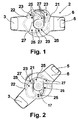
- FIG. 1 shows relative positions of a holder base and a base and casing of a ball joint in a holder's horizontal position
- Fig. 2 shows relative positions of the holder base and the base and casing of the ball joint in a holder's intermediate position
- Fig. 3 shows relative positions of the holder base and the base and casing of the ball joint in a holder's vertical position
- Fig. 4 - is a perspective view of one of the embodiments of the holder connected with the ball joint
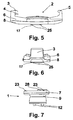
- Fig. 5 - is a side view of the holder without the ball joint, according to Fig. 4 , Fig.
- Fig. 6 - is a top view of the same holder without the ball joint
- Fig. 7 - is a side view of a ball joint body
- Fig. 8 - is the ball joint body, as per Fig. 7 , viewed at the base
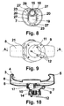
- Fig. 9 - is a rear view of the holder with the ball joint
- Fig. 10 - is a cross-section view of the same holder with the ball joint taken along the A-A line of Fig. 9
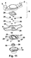
- Fig. 11 - is an explode view of the holder with the ball joint
- Fig. 12 - is the holder with the ball joint and a mobile phone resting in it, mounted in a cavity of a vehicle dashboard.
- a rotational holder with a ball joint, mounted to a dashboard of a motor vehicle, provided with a lowering mechanism, as depicted in Figs. 1-4 consists of two basic components: a ball joint (1), which casing forms a hanger fixed to the vehicle dashboard, and a holding unit (2), which is adapted to accommodate a mobile phone, not depicted in the drawings, or another electronic apparatus that may be useful in a car.
- the known holder is provided with two jaws: a fixed jaw (3) with a contact element (4) and a movable jaw (5), mounted slideably in an oblong body (6) of the holding unit (2). Inside the body (6) of the holding unit (2) there is a known moving and locking mechanism.
- a body of the ball joint (1) consists of a base (7) connected to a lower portion (8) of the holder body, and of a casing (9) forming a shield for a ball (10) of the ball joint (1).
- the casing (9) is favourably provided with a cover (11) with bolts (12), which are used to place and locate the holder on the dashboard, not depicted in the drawings.
- the cover (11) is connected with the casing (9) by means of a screw in a spring (14).
- Shapes of a lower surface of the lower portion (8) of the body (6) of the holding unit (2) and the base (7) of the ball joint (1) shall be adapted to ensure a relative motion of both parts triggered by a rotational motion of the body (6) and its concurrent vertical motion.
- the external surface of the lower portion (8) of the body (6) of the holding unit (2) (located under the body in Figs. 5 and 6 ) is provided with a symmetrical central hole (15) with a flange (16) surrounded by a toothed element (17) ( Figs. 2 10 , 11 ).
- an external surface of the ball joint (1) base (7) is provided with an oblong hole (19), on the edge of which there are two parallel tooth bars (20) that are adapted to engage alternatingly with the toothed element (17) ( Figs. 2 and 10 ).
- the external surface of the lower portion (8) of the body (6) of the holding unit (2) is provided with internal arcuate grooves (21) and external arcuate grooves (22), whereas the external surface of the base (7) of the ball joint (1) body is provided with three pins (23) arranged symmetrically.
- the pins (23) are adapted to engage with the arcuate grooves thus controlling the movement of the body (6) of the holding unit (2) so that it is lifted above the dashboard while being rotated around the axis of the central hole (15).
- the lower portion (8) of the body (6) of the holding unit (2) is additionally provided with a plurality of holes (24), in which small bolts (25) are flexibly mounted on an internal part of that portion (8).
- the small bolts (25) are supported by a pressure plate (29), which is adapted to provide a support for springs (26).
- the small bolts (25) are adapted to engage with holes (27) of the base (7) thus locking the holding unit (2) in its extreme horizontal or vertical position set.
- the assembled holder as depicted in Fig. 10 , is mounted to the dashboard by means of bolts (12) so that the holding unit (2) is in the horizontal position. In this position the holder is in the least distance to the dashboard and does not limit the driver's field of vision ( Fig. 1 ). In order to facilitate an operation of a phone keyboard or display, it is favourable to turn the holder into the vertical position. During the turn of the holder from the Fig. 1 position, via the Fig. 2 position to the Fig. 3 position, the holding unit (2) is concurrently moved vertically upwards.
- This complex movement is a result of the rotational motion of the holding unit (2), done manually, and its concurrent upward movement caused by an engagement of the rotating toothed element (17) and one of the toothed bars (20).
- the upward movement is also controlled by three pins (23), guided in the internal (21) and external arcuate grooves (22) of the lower portion (8) of the body (6).
- the holder may be returned to its horizontal position by means of both a further movement of the holding unit (2) or by its opposite movement. In both cases, the rotational movement of the holding unit (2) is accompanied by the vertical movement of the holding unit (2) towards the dashboard.
Landscapes
- Engineering & Computer Science (AREA)
- Mechanical Engineering (AREA)
- Fittings On The Vehicle Exterior For Carrying Loads, And Devices For Holding Or Mounting Articles (AREA)
- Telephone Set Structure (AREA)
Claims (7)
- La poignée tournante avec une rotule fixée au tableau de bord d'un véhicule mécanique ou le corps de la rotule (1) est fixé au tableau de bord, par contre la poignée principale (2) de la poignée tournante est fixée à la base (7) du corps de la rotule (1), sachant que la poignée tournante soit en plus équipée d'un mécanisme abaissant la poignée principale (2) en bas, vers le tableau de bord, durant la rotation, d'une position verticale jusqu'à la position horizontale et à l'envers, caractérisé en ce que le mécanisme abaissant est équipé de deux crémaillères opposées (20) à la base (7) du corps de la rotule (1) et d'une crémaillère (17) sur le corps (6) de la poignée principale (2), sachant que les crémaillères opposées (20) sont adaptées à la coopération avec la crémaillère (17).
- La poignée selon la revendication 1, caractérisé en ce que la crémaillère (17) entoure, d'une manière concentrique, un axe de l'orifice (15) se trouvant au milieu de la symétrie du corps (6) de la poignée principale (2).
- La poignée selon la revendication 1, caractérisé en ce que le corps de la rotule (1) est composé de la base (7) qui est adaptée au contact avec la partie inférieure (8) du corps (6) de la poignée principale (2) et du boîtier (9) fixé à la base (7) et équipé d'un couvercle (11), y fixé avec un vis dans un ressort (14).
- La poignée selon la revendication 3, caractérisé en ce que la partie inférieure (8) du corps (6) de la poignée principale (2) est équipée d'une came à rainures (21, 22) adaptées à la commande du mouvement vertical de la poignée principale (2), tandis que la base (7) du corps de la rotule (1) est équipée des goujons (23) qui sont adaptés à la coopération avec des rainures de la came (21, 22).
- La poignée selon la revendication 3 ou 4, caractérisé en ce que la base (7) du corps de la rotule (1) est équipée d'un orifice (19) qui est adapté au passage de la douille à brides (28) reliant avec des vis la base (7) et la partie inférieure (8) du corps (6) de la poignée principale (2).
- La poignée selon la revendication 3 ou 4, caractérisé en ce que la partie inférieure (8) du corps (6) de la poignée principale (2) d'un système des bouchons « champignons » (25) fixés d'une manière souple avec des ressorts (26) qui sont adaptés à bloquer la poignée principale (2) dans sa position extrême verticale ou horizontale.
- La poignée selon la revendication 6, caractérisé en ce que le système des « champignons » bloquant (25) est fermé par un plateau de pression (29) qui constitue un appui pour les ressorts (26).
Priority Applications (1)
| Application Number | Priority Date | Filing Date | Title |
|---|---|---|---|
| EP20100460032 EP2407351B1 (fr) | 2010-07-12 | 2010-07-12 | Support rotatif avec une rotule, monté sur un tableau de bord d'un véhicule. |
Applications Claiming Priority (1)
| Application Number | Priority Date | Filing Date | Title |
|---|---|---|---|
| EP20100460032 EP2407351B1 (fr) | 2010-07-12 | 2010-07-12 | Support rotatif avec une rotule, monté sur un tableau de bord d'un véhicule. |
Publications (2)
| Publication Number | Publication Date |
|---|---|
| EP2407351A1 EP2407351A1 (fr) | 2012-01-18 |
| EP2407351B1 true EP2407351B1 (fr) | 2012-10-31 |
Family
ID=43216390
Family Applications (1)
| Application Number | Title | Priority Date | Filing Date |
|---|---|---|---|
| EP20100460032 Not-in-force EP2407351B1 (fr) | 2010-07-12 | 2010-07-12 | Support rotatif avec une rotule, monté sur un tableau de bord d'un véhicule. |
Country Status (1)
| Country | Link |
|---|---|
| EP (1) | EP2407351B1 (fr) |
Families Citing this family (3)
| Publication number | Priority date | Publication date | Assignee | Title |
|---|---|---|---|---|
| CN102750968B (zh) * | 2012-06-30 | 2015-10-14 | 惠州市德赛西威汽车电子股份有限公司 | 一种多功能车载播放器 |
| CN104417445A (zh) * | 2013-08-23 | 2015-03-18 | 沈荣清 | 一种用于汽车中控台的手机支架 |
| EP3258222A1 (fr) * | 2016-06-16 | 2017-12-20 | Fly By Wire Systems France | Agencement de connecteur permettant de raccorder un module détecteur à un véhicule et procédé permettant de connecter le module de capteur pour le véhicule |
Family Cites Families (2)
| Publication number | Priority date | Publication date | Assignee | Title |
|---|---|---|---|---|
| US6397046B1 (en) * | 1999-03-17 | 2002-05-28 | Motorola, Inc. | Hang-up cup assembly |
| EP1853463A2 (fr) * | 2005-03-04 | 2007-11-14 | Viamichelin | Dispositif support constituant une station d'accueil pour equipement portable |
-
2010
- 2010-07-12 EP EP20100460032 patent/EP2407351B1/fr not_active Not-in-force
Also Published As
| Publication number | Publication date |
|---|---|
| EP2407351A1 (fr) | 2012-01-18 |
Similar Documents
| Publication | Publication Date | Title |
|---|---|---|
| US10933815B1 (en) | Apparatus for holding mobile device | |
| US20140003021A1 (en) | Holding Device for a Portable Communication Device | |
| WO2016200942A1 (fr) | Élément pour intérieur de véhicule | |
| KR20140069684A (ko) | 차량용 핸드폰 거치대 | |
| CN103448593A (zh) | 用于机动车的扶手装置以及具有扶手装置的机动车 | |
| US20190346080A1 (en) | Stand device | |
| JP2013256240A (ja) | 自動車用携帯機器ホルダ | |
| EP2407351A1 (fr) | Support rotatif avec une rotule, monté sur un tableau de bord d'un véhicule. | |
| CN209366042U (zh) | 一种翻盖式手机支架以及车辆内的扶手 | |
| CN205510171U (zh) | 车载手机支架 | |
| CN209201135U (zh) | 一种翻转式手机夹持装置 | |
| CN209381922U (zh) | 一种隐藏式手机夹持装置 | |
| CN214985143U (zh) | 车载pad支架 | |
| JP2013233862A (ja) | 車載用機器用の支持装置 | |
| CN213094258U (zh) | 一种带可拆分功能的手机壳支架 | |
| CN214480746U (zh) | 一种车载手机无线充电支架 | |
| CN210258267U (zh) | 一种可调节角度的车载hud | |
| CN215190667U (zh) | 一种航空飞行器模型支撑平台 | |
| CN211089170U (zh) | 车载手机无线充电装置、汽车仪表板总成及汽车 | |
| CN211860209U (zh) | 重力支架 | |
| CN210867810U (zh) | 一种横竖屏车载重力手机支架 | |
| CN208605885U (zh) | 一种便携式电子产品固定架 | |
| CN219619023U (zh) | 汽车后枕伸缩自锁支架装置 | |
| CN209833539U (zh) | 一种用于汽车的可调节手机放置座 | |
| CN222360921U (zh) | 一种可调节旋转车载手机支架底座 |
Legal Events
| Date | Code | Title | Description |
|---|---|---|---|
| AK | Designated contracting states |
Kind code of ref document: A1 Designated state(s): AL AT BE BG CH CY CZ DE DK EE ES FI FR GB GR HR HU IE IS IT LI LT LU LV MC MK MT NL NO PL PT RO SE SI SK SM TR |
|
| AX | Request for extension of the european patent |
Extension state: BA ME RS |
|
| PUAI | Public reference made under article 153(3) epc to a published international application that has entered the european phase |
Free format text: ORIGINAL CODE: 0009012 |
|
| 17P | Request for examination filed |
Effective date: 20120209 |
|
| GRAP | Despatch of communication of intention to grant a patent |
Free format text: ORIGINAL CODE: EPIDOSNIGR1 |
|
| RIC1 | Information provided on ipc code assigned before grant |
Ipc: B60R 11/02 20060101AFI20120427BHEP |
|
| GRAS | Grant fee paid |
Free format text: ORIGINAL CODE: EPIDOSNIGR3 |
|
| GRAA | (expected) grant |
Free format text: ORIGINAL CODE: 0009210 |
|
| AK | Designated contracting states |
Kind code of ref document: B1 Designated state(s): AL AT BE BG CH CY CZ DE DK EE ES FI FR GB GR HR HU IE IS IT LI LT LU LV MC MK MT NL NO PL PT RO SE SI SK SM TR |
|
| REG | Reference to a national code |
Ref country code: GB Ref legal event code: FG4D Ref country code: CH Ref legal event code: EP |
|
| REG | Reference to a national code |
Ref country code: AT Ref legal event code: REF Ref document number: 581804 Country of ref document: AT Kind code of ref document: T Effective date: 20121115 |
|
| REG | Reference to a national code |
Ref country code: IE Ref legal event code: FG4D |
|
| REG | Reference to a national code |
Ref country code: DE Ref legal event code: R096 Ref document number: 602010003442 Country of ref document: DE Effective date: 20121227 |
|
| REG | Reference to a national code |
Ref country code: AT Ref legal event code: MK05 Ref document number: 581804 Country of ref document: AT Kind code of ref document: T Effective date: 20121031 |
|
| REG | Reference to a national code |
Ref country code: LT Ref legal event code: MG4D |
|
| REG | Reference to a national code |
Ref country code: NL Ref legal event code: VDEP Effective date: 20121031 |
|
| PG25 | Lapsed in a contracting state [announced via postgrant information from national office to epo] |
Ref country code: SE Free format text: LAPSE BECAUSE OF FAILURE TO SUBMIT A TRANSLATION OF THE DESCRIPTION OR TO PAY THE FEE WITHIN THE PRESCRIBED TIME-LIMIT Effective date: 20121031 Ref country code: FI Free format text: LAPSE BECAUSE OF FAILURE TO SUBMIT A TRANSLATION OF THE DESCRIPTION OR TO PAY THE FEE WITHIN THE PRESCRIBED TIME-LIMIT Effective date: 20121031 Ref country code: HR Free format text: LAPSE BECAUSE OF FAILURE TO SUBMIT A TRANSLATION OF THE DESCRIPTION OR TO PAY THE FEE WITHIN THE PRESCRIBED TIME-LIMIT Effective date: 20121031 Ref country code: NL Free format text: LAPSE BECAUSE OF FAILURE TO SUBMIT A TRANSLATION OF THE DESCRIPTION OR TO PAY THE FEE WITHIN THE PRESCRIBED TIME-LIMIT Effective date: 20121031 Ref country code: IS Free format text: LAPSE BECAUSE OF FAILURE TO SUBMIT A TRANSLATION OF THE DESCRIPTION OR TO PAY THE FEE WITHIN THE PRESCRIBED TIME-LIMIT Effective date: 20130228 Ref country code: LT Free format text: LAPSE BECAUSE OF FAILURE TO SUBMIT A TRANSLATION OF THE DESCRIPTION OR TO PAY THE FEE WITHIN THE PRESCRIBED TIME-LIMIT Effective date: 20121031 Ref country code: NO Free format text: LAPSE BECAUSE OF FAILURE TO SUBMIT A TRANSLATION OF THE DESCRIPTION OR TO PAY THE FEE WITHIN THE PRESCRIBED TIME-LIMIT Effective date: 20130131 |
|
| PG25 | Lapsed in a contracting state [announced via postgrant information from national office to epo] |
Ref country code: SI Free format text: LAPSE BECAUSE OF FAILURE TO SUBMIT A TRANSLATION OF THE DESCRIPTION OR TO PAY THE FEE WITHIN THE PRESCRIBED TIME-LIMIT Effective date: 20121031 Ref country code: PL Free format text: LAPSE BECAUSE OF FAILURE TO SUBMIT A TRANSLATION OF THE DESCRIPTION OR TO PAY THE FEE WITHIN THE PRESCRIBED TIME-LIMIT Effective date: 20121031 Ref country code: LV Free format text: LAPSE BECAUSE OF FAILURE TO SUBMIT A TRANSLATION OF THE DESCRIPTION OR TO PAY THE FEE WITHIN THE PRESCRIBED TIME-LIMIT Effective date: 20121031 Ref country code: PT Free format text: LAPSE BECAUSE OF FAILURE TO SUBMIT A TRANSLATION OF THE DESCRIPTION OR TO PAY THE FEE WITHIN THE PRESCRIBED TIME-LIMIT Effective date: 20130228 Ref country code: GR Free format text: LAPSE BECAUSE OF FAILURE TO SUBMIT A TRANSLATION OF THE DESCRIPTION OR TO PAY THE FEE WITHIN THE PRESCRIBED TIME-LIMIT Effective date: 20130201 Ref country code: BE Free format text: LAPSE BECAUSE OF FAILURE TO SUBMIT A TRANSLATION OF THE DESCRIPTION OR TO PAY THE FEE WITHIN THE PRESCRIBED TIME-LIMIT Effective date: 20121031 |
|
| PG25 | Lapsed in a contracting state [announced via postgrant information from national office to epo] |
Ref country code: AT Free format text: LAPSE BECAUSE OF FAILURE TO SUBMIT A TRANSLATION OF THE DESCRIPTION OR TO PAY THE FEE WITHIN THE PRESCRIBED TIME-LIMIT Effective date: 20121031 |
|
| PG25 | Lapsed in a contracting state [announced via postgrant information from national office to epo] |
Ref country code: DK Free format text: LAPSE BECAUSE OF FAILURE TO SUBMIT A TRANSLATION OF THE DESCRIPTION OR TO PAY THE FEE WITHIN THE PRESCRIBED TIME-LIMIT Effective date: 20121031 Ref country code: BG Free format text: LAPSE BECAUSE OF FAILURE TO SUBMIT A TRANSLATION OF THE DESCRIPTION OR TO PAY THE FEE WITHIN THE PRESCRIBED TIME-LIMIT Effective date: 20130131 Ref country code: EE Free format text: LAPSE BECAUSE OF FAILURE TO SUBMIT A TRANSLATION OF THE DESCRIPTION OR TO PAY THE FEE WITHIN THE PRESCRIBED TIME-LIMIT Effective date: 20121031 Ref country code: SK Free format text: LAPSE BECAUSE OF FAILURE TO SUBMIT A TRANSLATION OF THE DESCRIPTION OR TO PAY THE FEE WITHIN THE PRESCRIBED TIME-LIMIT Effective date: 20121031 Ref country code: CZ Free format text: LAPSE BECAUSE OF FAILURE TO SUBMIT A TRANSLATION OF THE DESCRIPTION OR TO PAY THE FEE WITHIN THE PRESCRIBED TIME-LIMIT Effective date: 20121031 |
|
| PG25 | Lapsed in a contracting state [announced via postgrant information from national office to epo] |
Ref country code: IT Free format text: LAPSE BECAUSE OF FAILURE TO SUBMIT A TRANSLATION OF THE DESCRIPTION OR TO PAY THE FEE WITHIN THE PRESCRIBED TIME-LIMIT Effective date: 20121031 Ref country code: RO Free format text: LAPSE BECAUSE OF FAILURE TO SUBMIT A TRANSLATION OF THE DESCRIPTION OR TO PAY THE FEE WITHIN THE PRESCRIBED TIME-LIMIT Effective date: 20121031 |
|
| PLBE | No opposition filed within time limit |
Free format text: ORIGINAL CODE: 0009261 |
|
| STAA | Information on the status of an ep patent application or granted ep patent |
Free format text: STATUS: NO OPPOSITION FILED WITHIN TIME LIMIT |
|
| 26N | No opposition filed |
Effective date: 20130801 |
|
| PG25 | Lapsed in a contracting state [announced via postgrant information from national office to epo] |
Ref country code: ES Free format text: LAPSE BECAUSE OF FAILURE TO SUBMIT A TRANSLATION OF THE DESCRIPTION OR TO PAY THE FEE WITHIN THE PRESCRIBED TIME-LIMIT Effective date: 20130211 |
|
| REG | Reference to a national code |
Ref country code: DE Ref legal event code: R097 Ref document number: 602010003442 Country of ref document: DE Effective date: 20130801 |
|
| PG25 | Lapsed in a contracting state [announced via postgrant information from national office to epo] |
Ref country code: CY Free format text: LAPSE BECAUSE OF FAILURE TO SUBMIT A TRANSLATION OF THE DESCRIPTION OR TO PAY THE FEE WITHIN THE PRESCRIBED TIME-LIMIT Effective date: 20121031 |
|
| PG25 | Lapsed in a contracting state [announced via postgrant information from national office to epo] |
Ref country code: MC Free format text: LAPSE BECAUSE OF FAILURE TO SUBMIT A TRANSLATION OF THE DESCRIPTION OR TO PAY THE FEE WITHIN THE PRESCRIBED TIME-LIMIT Effective date: 20121031 |
|
| REG | Reference to a national code |
Ref country code: IE Ref legal event code: MM4A |
|
| REG | Reference to a national code |
Ref country code: FR Ref legal event code: ST Effective date: 20140331 |
|
| PG25 | Lapsed in a contracting state [announced via postgrant information from national office to epo] |
Ref country code: FR Free format text: LAPSE BECAUSE OF NON-PAYMENT OF DUE FEES Effective date: 20130731 |
|
| PG25 | Lapsed in a contracting state [announced via postgrant information from national office to epo] |
Ref country code: IE Free format text: LAPSE BECAUSE OF NON-PAYMENT OF DUE FEES Effective date: 20130712 |
|
| REG | Reference to a national code |
Ref country code: CH Ref legal event code: PL |
|
| PG25 | Lapsed in a contracting state [announced via postgrant information from national office to epo] |
Ref country code: LI Free format text: LAPSE BECAUSE OF NON-PAYMENT OF DUE FEES Effective date: 20140731 Ref country code: CH Free format text: LAPSE BECAUSE OF NON-PAYMENT OF DUE FEES Effective date: 20140731 |
|
| PG25 | Lapsed in a contracting state [announced via postgrant information from national office to epo] |
Ref country code: SM Free format text: LAPSE BECAUSE OF FAILURE TO SUBMIT A TRANSLATION OF THE DESCRIPTION OR TO PAY THE FEE WITHIN THE PRESCRIBED TIME-LIMIT Effective date: 20121031 |
|
| PG25 | Lapsed in a contracting state [announced via postgrant information from national office to epo] |
Ref country code: MT Free format text: LAPSE BECAUSE OF FAILURE TO SUBMIT A TRANSLATION OF THE DESCRIPTION OR TO PAY THE FEE WITHIN THE PRESCRIBED TIME-LIMIT Effective date: 20121031 Ref country code: TR Free format text: LAPSE BECAUSE OF FAILURE TO SUBMIT A TRANSLATION OF THE DESCRIPTION OR TO PAY THE FEE WITHIN THE PRESCRIBED TIME-LIMIT Effective date: 20121031 |
|
| PG25 | Lapsed in a contracting state [announced via postgrant information from national office to epo] |
Ref country code: LU Free format text: LAPSE BECAUSE OF NON-PAYMENT OF DUE FEES Effective date: 20130712 Ref country code: HU Free format text: LAPSE BECAUSE OF FAILURE TO SUBMIT A TRANSLATION OF THE DESCRIPTION OR TO PAY THE FEE WITHIN THE PRESCRIBED TIME-LIMIT; INVALID AB INITIO Effective date: 20100712 Ref country code: MK Free format text: LAPSE BECAUSE OF FAILURE TO SUBMIT A TRANSLATION OF THE DESCRIPTION OR TO PAY THE FEE WITHIN THE PRESCRIBED TIME-LIMIT Effective date: 20121031 |
|
| PG25 | Lapsed in a contracting state [announced via postgrant information from national office to epo] |
Ref country code: AL Free format text: LAPSE BECAUSE OF FAILURE TO SUBMIT A TRANSLATION OF THE DESCRIPTION OR TO PAY THE FEE WITHIN THE PRESCRIBED TIME-LIMIT Effective date: 20121031 |
|
| PGFP | Annual fee paid to national office [announced via postgrant information from national office to epo] |
Ref country code: GB Payment date: 20210824 Year of fee payment: 12 Ref country code: DE Payment date: 20210831 Year of fee payment: 12 |
|
| REG | Reference to a national code |
Ref country code: DE Ref legal event code: R119 Ref document number: 602010003442 Country of ref document: DE |
|
| GBPC | Gb: european patent ceased through non-payment of renewal fee |
Effective date: 20220712 |
|
| PG25 | Lapsed in a contracting state [announced via postgrant information from national office to epo] |
Ref country code: GB Free format text: LAPSE BECAUSE OF NON-PAYMENT OF DUE FEES Effective date: 20220712 Ref country code: DE Free format text: LAPSE BECAUSE OF NON-PAYMENT OF DUE FEES Effective date: 20230201 |