EP2407416A1 - Herstellungsverfahren einer Vorrichtung mit einer Membran, die eine Flüssigkeit einschließt - Google Patents
Herstellungsverfahren einer Vorrichtung mit einer Membran, die eine Flüssigkeit einschließt Download PDFInfo
- Publication number
- EP2407416A1 EP2407416A1 EP20110172540 EP11172540A EP2407416A1 EP 2407416 A1 EP2407416 A1 EP 2407416A1 EP 20110172540 EP20110172540 EP 20110172540 EP 11172540 A EP11172540 A EP 11172540A EP 2407416 A1 EP2407416 A1 EP 2407416A1
- Authority
- EP
- European Patent Office
- Prior art keywords
- membrane
- substrates
- fluid
- cavity
- substrate
- Prior art date
- Legal status (The legal status is an assumption and is not a legal conclusion. Google has not performed a legal analysis and makes no representation as to the accuracy of the status listed.)
- Granted
Links
Images



Classifications
-
- G—PHYSICS
- G02—OPTICS
- G02B—OPTICAL ELEMENTS, SYSTEMS OR APPARATUS
- G02B3/00—Simple or compound lenses
- G02B3/12—Fluid-filled or evacuated lenses
- G02B3/14—Fluid-filled or evacuated lenses of variable focal length
-
- F—MECHANICAL ENGINEERING; LIGHTING; HEATING; WEAPONS; BLASTING
- F04—POSITIVE - DISPLACEMENT MACHINES FOR LIQUIDS; PUMPS FOR LIQUIDS OR ELASTIC FLUIDS
- F04B—POSITIVE-DISPLACEMENT MACHINES FOR LIQUIDS; PUMPS
- F04B43/00—Machines, pumps, or pumping installations having flexible working members
- F04B43/02—Machines, pumps, or pumping installations having flexible working members having plate-like flexible members, e.g. diaphragms
- F04B43/04—Pumps having electric drive
- F04B43/043—Micropumps
-
- G—PHYSICS
- G02—OPTICS
- G02B—OPTICAL ELEMENTS, SYSTEMS OR APPARATUS
- G02B26/00—Optical devices or arrangements for the control of light using movable or deformable optical elements
- G02B26/004—Optical devices or arrangements for the control of light using movable or deformable optical elements based on a displacement or a deformation of a fluid
Definitions
- the present invention relates to the manufacture of membrane devices trapping a fluid.
- the fluid will be incompressible.
- a fluid is said to be incompressible when its volume remains almost constant under the action of an external pressure.
- the fluid may be a liquid or a gel, the gases not being incompressible.
- Such a membrane device trapping an incompressible fluid can serve for example adjustable focal length lens, adjustable curvature mirror or micro pump.
- the invention can of course be applied to other devices requiring to place a membrane on a cavity containing a fluid whether it is incompressible or not.
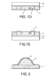
- a substrate 6 is then secured to the other main face of the frame 1, it will close the cavity 5 to prevent the fluid 4 from escaping ( figure 1D ).
- the last figure 1E shows the membrane equipped with actuating means 7 to move it to drive the fluid 4 towards the central part of the cavity 5.
- a disadvantage of the process described in these documents is that it is only suitable for sufficiently thick membranes, typically with a thickness greater than 50 microns for a polydimethylsiloxane membrane. Thinner membranes, very flexible or very large are too fragile to be carried on the frame. The applications listed more high require membranes of very small thickness, less than a few tens of micrometers, and sufficiently flexible to be able to deform significantly when operating the actuating means.
- the actuating means can be found only on the face of the membrane opposite the fluid otherwise, during the transfer of the membrane the risk of deformation and damage to the membrane are important.
- Another disadvantage of this method is that it is practiced at low pressure, of the order of 4.10 -2 HPa, which excludes the use as a fluid, a gas and most liquids that will evaporate during the deposit CVD.
- Another technique described for example in the patent application FR 2 919 073 is to deposit a sacrificial material in a cavity which is equipped with a support, to deposit the membrane on the sacrificial material by overflowing on the support so as to anchor thereon, to eliminate the sacrificial material by a hole drilled in the support and replace it with the fluid, then to plug the hole of the support.
- the disadvantage of this technique is due to sacrificial material. Indeed, it is difficult to eliminate, it takes a lot of time, several dozen hours, and we are never sure that everything has been eliminated. If sacrificial material remains, it may disrupt the operation of actuating means that would be bathed by the fluid or pollute the fluid.
- the object of the present invention is precisely to propose a process for producing a membrane device trapping a fluid that does not have the limitations and difficulties mentioned above.
- the method according to the invention makes it possible to use a wide range of fluids and materials for the membrane.
- Another object of the invention is to provide a membrane device trapping a fluid in which the deformation of the membrane at rest can be provided in advance, this deformation may be zero.
- Yet another object of the invention is to provide a membrane device trapping a fluid in which the membrane can be equipped with at least one instrument such as actuating means or a sensor disposed on the side of the fluid.
- a further object of the invention is to provide a membrane device trapping a fluid without having to resort to the use of a sacrificial material that could cause problems when using the membrane device if it does not. has not been properly eliminated.
- the fluid may be deposited on one of the substrates or distributed over the two substrates before the two substrates are assembled.
- the fluid can be introduced into the cavity once the two substrates are assembled.
- the introduction can be done through at least one through hole in one of the substrates and / or in a wall.
- the buffer layer can be removed to release the membrane at least in its central portion.
- the instrument is preferably in contact with the fluid.
- the formation of the walls on one of the substrates may be done by depositing a cord material, this material may be adhesive, and / or by etching the substrate and / or by depositing a modeling layer on the substrate, then etching the modeling layer and / or using a preformed modeling layer.
- the membrane may be deposited by chemical vapor deposition if it is inorganic or parylene, or by spin coating or by plating a film if it is organic.
- the assembly of the two substrates can be done by gluing.
- the fluid can be deposited or introduced by a so-called dispensing technique or by projection.
- the fluid can be in the form of liquid, gas or gel.
- FIGS. 3A to 3E A first example of the method which is the subject of the invention will now be described with reference to the FIGS. 3A to 3E .
- the substrates 110, 120 may be of mineral material such as glass, quartz, sapphire, silicon or other semiconductor material, a metal. Alternatively, they may be made of organic material such as polyethylene terephthalate PET, polyethylene naphthalate PEN, polymethyl methacrylate PMMA, polycarbonate PC. If the application of the device obtained by the process according to the invention is a liquid lens with a variable focal length, one of the substrates remaining at the end of the process for trapping the fluid will be chosen to be transparent to the optical radiation that has to pass through the lens.
- a membrane 111 is placed on one of the substrates, in this case, on the first substrate 110.
- the membrane 111 covers one of the main faces of the first substrate 110, it has a free face 111.1 and a face 111.2. contact with the first substrate 110.
- the membrane 111 may be made of organic materials such as polydimethylsiloxane, polymethyl methacrylate, polyethylene terephthalate, polycarbonate, parylene, epoxy or silicone resins, photosensitive resins, or mineral materials such as silicon, silicon oxide, silicon nitride, silicon carbide, polycrystalline silicon, titanium nitride, diamond carbon, tin and indium oxide, aluminum, copper, nickel.
- organic materials such as polydimethylsiloxane, polymethyl methacrylate, polyethylene terephthalate, polycarbonate, parylene, epoxy or silicone resins, photosensitive resins, or mineral materials such as silicon, silicon oxide, silicon nitride, silicon carbide, polycrystalline silicon, titanium nitride, diamond carbon, tin and indium oxide, aluminum, copper, nickel.
- the membrane will be transparent to the optical radiation to pass through it and in the mirror application, it will be reflective to the incident optical radiation.
- the membrane 111 may be deposited on the first substrate by CVD chemical vapor deposition, in particular if it is mineral or in parylene or by spin coating for other organic materials. Another way is to use for the membrane 111 an organic film, for example roll or plate that is just pressed on the first substrate.
- photosensitive resins allows once the membrane has been deposited from the engrave with a simple step of lithography to delimit its outline.
- An instrument is an object manufactured for a particular purpose.
- This instrument can be in whole or in part a means for actuating the membrane, a sensor, such as an environmental sensor capable of detecting for example the humidity, the pressure, the temperature, the nature of the residual gases, or such as a sensor.
- movement such as a gyroscope, an accelerometer, a magnetometer, or other.
- the instrument 112.1 is shown as one of the electrodes of an electrostatic actuator with at least one pair of electrodes placed opposite. It is made on the free face 111.1 of the membrane 111. It will be seen that the second substrate 120 will be equipped with the other electrode of the pair.
- the instrument 112.1 may be, in the case where it is a means for actuating the membrane, an electrically conductive electrode as just described, an element made of piezoelectric material, of magnetic material, electroactive polymer that deforms under the effect of an electric current.
- At least one wall 113 is formed on at least one of the substrates 110, 120, this wall 113 contributing to laterally delimiting a cavity 114 for receiving a fluid.
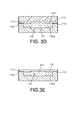
- the membrane 111 serves also to trap the fluid in the cavity 114 ( figure 3B ).
- the wall 114 is made on the second substrate 120.
- the second substrate 120 will then serve as a bottom 115 to the cavity 114. It is understood that one could make a wall on the first substrate, on the side of the membrane or on both substrates, in this case, the walls of the two substrates must cooperate to define the cavity.
- the wall 113 is made by etching a bowl 116 in the central portion of the second substrate 120, the edges of the bowl forming the wall 113 and the bottom of the bowl 116 forming the bottom 115 of the cavity.
- the etching can be done by reactive ion etching, by physical plasma etching, for example xenon difluoride XeF 2 or sulfur hexafluoride SF 6 , by wet chemical etching with, for example, TMAH or potassium hydroxide KOH.
- a bead of suitable material on the second substrate.
- a negative bonding resin such as benzocyclobutene BCB or SiNR polymer siloxane can be used to form the bead.
- the cord allows both to define the cavity and to seal the first and the second substrate.
- Other glues may be envisaged such as glues thermosetting or curing glues under the effect of ultraviolet.
- a deposition step on the second substrate of a mineral material such as silicon oxide or silicon nitride, a step of lithography and etching of the deposited material.
- the bottom 115 of the bowl 116 is equipped with another instrument 112.2 which, in this example, is another electrode to cooperate and form a pair with the electrode 112.1 carried by the membrane 111 (FIG. figure 3B ).
- the bowl is filled with fluid 117 ( figure 3C ). It is understood that this step could take place later.
- the fluid 117 may be a gas, a liquid or a gel.
- an incompressible fluid will preferably be chosen, it will therefore be a liquid or a gel. This gives better performance during actuation. It is of course possible that the fluid is compressible and a gas can then be used.
- the filling of the bowl 116 can be done using a syringe or the like, that is to say by a so-called dispensing technique or by projection from a nozzle.
- the assembly is placed at the time of assembly in an enclosure containing the gas at a desired pressure and having a desired composition.
- the volume of fluid placed in the bowl 116 must be adapted to the volume that will have the cavity once closed. It may be desired that the membrane 111 is slightly curved or that it is flat at rest.
- the bottom 115 of the bowl 116 must have a wettability such that the liquid or the gel spread as well as possible on the bottom 115, so that the entire volume of the cavity 114 can be easily filled.
- the fluid may be a gas such as, for example, air, nitrogen, helium, a liquid such as propylene carbonate, water, a liquid index, an optical oil, an ionic liquid, a gel such as an elastomer, for example polydimethylsiloxane PDMS.
- a gas such as, for example, air, nitrogen, helium
- a liquid such as propylene carbonate
- water a liquid index
- an optical oil such as an ionic liquid
- a gel such as an elastomer, for example polydimethylsiloxane PDMS.
- the fluid 117 is a liquid or a gel
- the fluid could be deposited on the first substrate 110, on the membrane side 111, or the fluid 117 deposited on both the first substrate 110 and the second substrate 120.
- the first substrate 110 and the second substrate 120 are then assembled by superimposing them and placing the membrane opposite the bowl, so as to perfect the cavity and trap the fluid 117 (FIG. 3D figure ).
- This assembly can be done by gluing, choosing an adhesive 118 and a bonding mode compatible with the fluid 117 to be trapped.
- the temperature and pressure conditions must avoid evaporation of the fluid 117.
- An ultraviolet activated bonding can be envisaged for fluids 117 evaporating at ambient temperature. This obviously assumes that one of the substrates 110, 120, at least, is transparent to ultraviolet. Some thermal collages can be done from 80 ° C. The bonding can be done in an enclosure in which the atmosphere, the pressure and the temperature are controlled so that the fluid does not evaporate.
- the first substrate 110 is eliminated in its entirety. This total elimination is suitable if the membrane 111 is sealingly attached to the wall 113 of the cavity 114. If there are risks of delamination, it is preferable to eliminate the first substrate only in its central part. The membrane is at least partly held by the fluid during its release.
- the removal of the first substrate 110 can be done for example by reactive ion etching (RIE reactive ion etching) and preferably by deep reactive ion etching (DRIE deep reactive ion etching). What distinguishes the two methods is the engraving depth. The typical depths of the RIE engravings are limited to a few micrometers and the etch rates are up to about one micrometer per minute. Gravure DRIE engraves much deeper patterns, up to about 600 micrometers or more, at speeds of the order of twenty micrometers per minute. The DRIE engraving is therefore well suited for this application.
- RIE reactive ion etching reactive ion etching
- DRIE deep reactive ion etching deep reactive ion etching
- the first substrate 110 is silicon, it is also possible to perform a physical plasma etching, for example of XeF 2 or SF 6, or a wet chemical etching with, for example, tetramethylammonium hydroxide TMAH or sodium hydroxide. potassium KOH.
- a physical plasma etching for example of XeF 2 or SF 6, or a wet chemical etching with, for example, tetramethylammonium hydroxide TMAH or sodium hydroxide. potassium KOH.
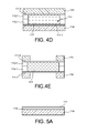
- FIGS. 4A to 4E another example of the method according to the invention will be described.
- a first substrate 110 and a second substrate 120 we now we place a membrane 111.1, 111.2 on each of the substrates 110, 120 ( Figure 4A ).
- a cup 116.1, 116.2 is formed on each of the substrates 110, 120 delimited by one or more walls 113.1, 113.2 (FIG. Figure 4B ).
- the walls 113.1, 113.2 of the Figure 4B contribute to laterally defining a cavity, they are located above the substrates 110, 120.
- the walls 113.1, 113.2 may be formed by a bead of adhesive, for example, negative bonding resin such as for example the resin based on benzocyclobutene BCB or siloxane polymer (SiNR).
- adhesive for example, negative bonding resin such as for example the resin based on benzocyclobutene BCB or siloxane polymer (SiNR).
- SiNR siloxane polymer
- the two glue beads 113.1, 113.2 do not necessarily have the same height, they can have constant or different heights depending on the location. They are complementary in terms of thickness, the cavity 114 once completed having a substantially constant wall 114.
- the cords 113.1, 113.2 may be discontinuous or not and complementary in terms of extent on the substrates 110, 120, which means that one will extend over at least a first portion of the perimeter of the cavity and the other on at least a second portion of the perimeter of the cavity, the two parts covering the entire perimeter of the completed cavity.
- thermosetting glues or photocurable UV.
- glues can be deposited on the substrates by screen printing or by dispensing.
- Non-adhesive cords 113.1, 113.2 of non-adhesive material could of course be used.
- the non-adhesive cords are generally made of polymerized materials such as benzocyclobutene BCB or SU8 resin unlike adhesive cords. It is also possible to produce the non-adhesive beads, as described above, by deposition, lithography and etching steps of inorganic materials such as silicon oxide or silicon nitride.
- one bead could be adhesive and not the other, if at least two cords are provided.
- each bowl 116.1, 116.2 has a bottom 115.1, 115.2 formed by the membrane and not directly the substrate as in the previous example.
- the two substrates 110, 120 are then assembled together by stacking them.
- Cuvettes 116.1, 116.2 are arranged face to face so as to trap fluid 117 between the two membranes 111.1, 111.2 (FIG. figure 4D ). If at least one of the cords 113.1, 113.2 used to delimit the cavity is adhesive, this assembly is done without problem. If none of the cords is adhesive, place glue on at least one of the cords. This assembly can be done with fluid as a liquid because the volumes are low and surface voltages are sufficient.
- the two substrates 110, 120 can then be completely or partially removed, to release the two membranes 111.1, 111.2 at least in their central part.
- the bottom 115 of the bowl 116 should allow to spread the fluid as much as possible 117.
- the bottom is made by the membranes. This condition is still desirable in the second example, but, moreover, insofar as the walls delimiting the cavity are generally not in the same material as the bottoms, it is preferable for each substrate that the wall is made in a material having a lower wettability than the bottom so as to avoid a fluid overflow.
- this stress preferably being a tension to prevent any buckling phenomenon at rest, it is recommended to insert a buffer layer 119 between the first substrate 110 and the 111.
- This buffer layer has the desired state of stress for the membrane.
- the membrane stress can be determined by simulation from parameters related to the membrane, to the buffer layer and possibly to at least one other layer that would be present, these parameters being, for example, their initial stress state, their Young's modulus. , their thickness. Once released, the membrane will not have the same constraint as the buffer layer. The stress of the released membrane depends on the parameters mentioned above.
- This buffer layer 119 may be made of silicon oxide or silicon nitride, for example. It can be carried out by plasma-activated vapor deposition PECVD. The buffer layer 119 could have been used in the two previous embodiments.
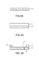
- the second substrate 120 will serve as a basis for modeling the cavity ( Figure 5B ).
- a layer 121 intended to be shaped to form the wall 113 of the cavity ( Figure 5C ).
- a drawn layer for example made of polyethylene terephthalate PET, of polyethylene naphthalate PEN, of polymethyl methacrylate PMMA, of polycarbonate PC.
- the modeling layer may be obtained by depositing a mineral material, such as silicon oxide or silicon nitride, and lithography and etching operations.
- a mineral material such as silicon oxide or silicon nitride
- the modeling layer 121 is kept only at what will become the wall 113 of the cavity 114 ( figure 5D ).
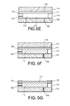
- FIG. 5E the assembly of the two substrates 110, 120 has been illustrated in order to finalize the cavity 114.
- the membrane 111 is bonded to the wall 113 of the cavity 114.
- An adhesive seal 124 has been inserted between the membrane and the top part. of the wall 113 of the cavity 114.
- At least one through hole 122 is pierced in the second substrate and the fluid 117 is injected via this through hole 121.
- the through hole 122 opens out at the bottom 115 of the cavity 114.
- the through hole 117 is then plugged, the plug carrying reference 123 ( figure 5F ).
- the through holes 122 were drilled before assembling the two substrates.
- the drilling can be DRIE or wet etching.
- Other methods that are also suitable for other types of substrate are laser drilling, machining, sanding, for example.
- the figure 5G shows the first substrate 110 which has been completely removed and the buffer layer 119 only partially. It remains at the wall of the cavity. She could have been eliminated totally.
- the membrane 111 has a central portion which is released.
- the buffer layer 119 may have a temporary membership property. In this case, it is totally removed. It is also possible to introduce, if the buffer layer does not have this temporary adhesion property, an additional layer between the buffer layer and the substrate, having this temporary adhesion property.
- the buffer layer may also serve to control the stress in the membrane and / or as just described to remove the substrate when it has this temporary adhesion property.
- the temporary adhesion can be obtained for example with a material whose adhesion decreases when the temperature is increased.
- a material whose adhesion decreases when the temperature is increased For example, for the buffer layer that has this temporary adhesion property or for the additional layer of Brewer Science HT 1010-type glue. If there is the additional layer, the buffer layer may be of another material.
- the buffer layer is made of silicon oxide or silicon nitride, for example, it can also be removed by reactive ion etching or by wet chemical etching with, for example, hydrofluoric acid for the oxide of silicon or silicon dioxide. orthophosphoric acid for silicon nitride.
- the process according to the invention makes it possible to widen the range of materials that can be used for the membrane, especially for thin layers, less than about 50 micrometers, or even less than 10 micrometers and for example between 1 and 5 micrometers.
- the method of the invention makes it possible, by releasing the membrane after assembly of the two substrates and filling the cavity with the fluid, to offer the membrane, during its release, a mechanical hold by the fluid trapped in the cavity.
- the release of the membrane after encapsulation allows the fluid which is trapped and in contact with it to participate in its maintenance and possibly influence its deformation.
- the membrane may have a thickness of less than 10 micrometers for diameters greater than one millimeter.
- Such a membrane may have a weak Young's modulus, for example less than 10 GPa. It is then possible to use for the realization of fine organic materials. Such materials could not be used if the membrane was released before filling.
- the flexibility of the membrane can be characterized by deformation during an actuation greater than its thickness, which corresponds to a mechanical regime of large deformations.
- the release of the membrane after filling is much easier than the release before filling.
- strong constraints are generated on the handling of the substrates because of the fragility of the membrane and on the choice of processes to use.
- a deep reactive ion etching method can not be used because of the pressure difference between the suction of the substrate holder and the vacuum of the chamber. This difference in pressure could cause a rupture of the membrane.
- the method which is the subject of the invention also makes it possible to better control the deformation of the membrane at rest, especially as the fluid is incompressible.
- the presence of an incompressible fluid that is to say a liquid or an incompressible gel, is advantageous compared to configurations with a compressible fluid because the membrane can rely on the incompressible fluid without suffering the effects of differences in pressure between the two faces of the membrane.
- This makes it possible to prevent diaphragm bursting due to the force exerted by the fluid when the device is evacuated, during the step of removing the substrate by reactive ion etching, or to have membrane bonding effects on the membrane. bottom of the cavity if the pressure in the cavity is too low at the end of the process.
Landscapes
- Physics & Mathematics (AREA)
- Engineering & Computer Science (AREA)
- General Physics & Mathematics (AREA)
- Optics & Photonics (AREA)
- Mechanical Engineering (AREA)
- General Engineering & Computer Science (AREA)
- Micromachines (AREA)
- Separation Using Semi-Permeable Membranes (AREA)
Applications Claiming Priority (1)
| Application Number | Priority Date | Filing Date | Title |
|---|---|---|---|
| FR1055664A FR2962557B1 (fr) | 2010-07-12 | 2010-07-12 | Procede de fabrication d'un dispositif a membrane emprisonnant un fluide |
Publications (2)
| Publication Number | Publication Date |
|---|---|
| EP2407416A1 true EP2407416A1 (de) | 2012-01-18 |
| EP2407416B1 EP2407416B1 (de) | 2015-10-07 |
Family
ID=43447720
Family Applications (1)
| Application Number | Title | Priority Date | Filing Date |
|---|---|---|---|
| EP11172540.4A Active EP2407416B1 (de) | 2010-07-12 | 2011-07-04 | Herstellungsverfahren einer Vorrichtung mit einer Membran, die eine Flüssigkeit einschließt |
Country Status (4)
| Country | Link |
|---|---|
| US (1) | US8551352B2 (de) |
| EP (1) | EP2407416B1 (de) |
| JP (1) | JP5858666B2 (de) |
| FR (1) | FR2962557B1 (de) |
Cited By (1)
| Publication number | Priority date | Publication date | Assignee | Title |
|---|---|---|---|---|
| EP3009678A1 (de) * | 2014-10-17 | 2016-04-20 | Commissariat à l'Énergie Atomique et aux Énergies Alternatives | Vorrichtung zum kühlen mit wärmeübertragungsmedium für elektronische bauteile |
Families Citing this family (13)
| Publication number | Priority date | Publication date | Assignee | Title |
|---|---|---|---|---|
| DK2969479T3 (da) | 2013-03-13 | 2021-08-02 | Illumina Inc | Væskeanordninger i flere lag og fremgangsmåder til deres fremstilling |
| FR3015699B1 (fr) | 2013-12-20 | 2016-02-05 | Wavelens | Dispositif optique pour stabilisation d'images |
| FR3019315B1 (fr) | 2014-03-25 | 2017-09-08 | Wavelens | Dispositif optique a membrane deformable |
| KR102692744B1 (ko) * | 2017-06-30 | 2024-08-06 | 폴라이트 에이에스에이 | 광학적 이미지 안정화 및 포커스 조정을 위한 렌즈 어셈블리 |
| WO2020160545A1 (en) * | 2019-02-01 | 2020-08-06 | Averatek Corporation | Coating of nano-scaled cavities |
| CN116745681A (zh) * | 2020-11-05 | 2023-09-12 | 苹果公司 | 具有液体透镜的电子设备 |
| FR3123344A1 (fr) | 2021-05-31 | 2022-12-02 | Commissariat A L'energie Atomique Et Aux Energies Alternatives | Microsystème électromécanique |
| CN115480327A (zh) * | 2021-05-31 | 2022-12-16 | 宁波舜宇光电信息有限公司 | 摄像模组及其光学镜头和变焦方法 |
| FR3123343B1 (fr) | 2021-05-31 | 2023-05-19 | Commissariat Energie Atomique | Microsystème électromécanique |
| CN115963586B (zh) * | 2021-05-31 | 2024-12-24 | 宁波舜宇光电信息有限公司 | 变焦镜片单元及其制造方法和应用 |
| CN117295981A (zh) * | 2021-05-31 | 2023-12-26 | 宁波舜宇光电信息有限公司 | 摄像模组及其光学镜头、变焦镜片单元、变焦方法、制造方法及其应用 |
| CN115933022B (zh) * | 2021-05-31 | 2025-03-25 | 宁波舜宇光电信息有限公司 | 变焦镜片单元及其制造方法以及变焦镜片单元的应用 |
| CN115480326B (zh) * | 2021-05-31 | 2024-06-11 | 宁波舜宇光电信息有限公司 | 摄像模组及其光学镜头、变焦镜片单元以及变焦方法 |
Citations (6)
| Publication number | Priority date | Publication date | Assignee | Title |
|---|---|---|---|---|
| US3718140A (en) * | 1971-10-13 | 1973-02-27 | A Yamauchi | Nursing bottle nipple |
| US20020106867A1 (en) * | 2000-11-02 | 2002-08-08 | Eui-Hyeok Yang | Wafer-level transfer of membranes in semiconductor processing |
| WO2005109043A1 (en) * | 2004-05-07 | 2005-11-17 | Koninklijke Philips Electronics N.V. | Electrowetting cell and method of manufacturing thereof |
| FR2889633A1 (fr) * | 2005-08-08 | 2007-02-09 | Commissariat Energie Atomique | Dispositif d'actionnement a membrane flexible commandee par electromouillage |
| US20080053236A1 (en) * | 2006-08-31 | 2008-03-06 | Evigia Systems, Inc. | Capacitive pressure sensor and method therefor |
| FR2919073A1 (fr) | 2007-07-19 | 2009-01-23 | Commissariat Energie Atomique | Dispositif optique a moyens d'actionnement d'une membrane deformable compacts |
Family Cites Families (10)
| Publication number | Priority date | Publication date | Assignee | Title |
|---|---|---|---|---|
| US4444471A (en) * | 1982-03-12 | 1984-04-24 | Polaroid Corporation | Variable focus lens system employing elastomeric lens |
| GB2183059B (en) * | 1985-11-05 | 1989-09-27 | Michel Treisman | Suspension system for a flexible optical membrane |
| JPH0749404A (ja) * | 1993-08-05 | 1995-02-21 | Nippondenso Co Ltd | 可変焦点レンズ |
| US5668620A (en) * | 1994-04-12 | 1997-09-16 | Kurtin; Stephen | Variable focal length lenses which have an arbitrarily shaped periphery |
| US5705018A (en) * | 1995-12-13 | 1998-01-06 | Hartley; Frank T. | Micromachined peristaltic pump |
| DE50003276D1 (de) * | 1999-05-17 | 2003-09-18 | Fraunhofer Ges Forschung | Mikromechanische pumpe |
| SG105459A1 (en) * | 2000-07-24 | 2004-08-27 | Micron Technology Inc | Mems heat pumps for integrated circuit heat dissipation |
| US7646544B2 (en) * | 2005-05-14 | 2010-01-12 | Batchko Robert G | Fluidic optical devices |
| JP4984875B2 (ja) * | 2006-07-10 | 2012-07-25 | ソニー株式会社 | レンズアレイ |
| KR20080043106A (ko) * | 2006-11-13 | 2008-05-16 | 삼성전자주식회사 | 광학렌즈 및 그 제조방법 |
-
2010
- 2010-07-12 FR FR1055664A patent/FR2962557B1/fr active Active
-
2011
- 2011-07-04 EP EP11172540.4A patent/EP2407416B1/de active Active
- 2011-07-07 US US13/177,840 patent/US8551352B2/en active Active
- 2011-07-11 JP JP2011152957A patent/JP5858666B2/ja active Active
Patent Citations (6)
| Publication number | Priority date | Publication date | Assignee | Title |
|---|---|---|---|---|
| US3718140A (en) * | 1971-10-13 | 1973-02-27 | A Yamauchi | Nursing bottle nipple |
| US20020106867A1 (en) * | 2000-11-02 | 2002-08-08 | Eui-Hyeok Yang | Wafer-level transfer of membranes in semiconductor processing |
| WO2005109043A1 (en) * | 2004-05-07 | 2005-11-17 | Koninklijke Philips Electronics N.V. | Electrowetting cell and method of manufacturing thereof |
| FR2889633A1 (fr) * | 2005-08-08 | 2007-02-09 | Commissariat Energie Atomique | Dispositif d'actionnement a membrane flexible commandee par electromouillage |
| US20080053236A1 (en) * | 2006-08-31 | 2008-03-06 | Evigia Systems, Inc. | Capacitive pressure sensor and method therefor |
| FR2919073A1 (fr) | 2007-07-19 | 2009-01-23 | Commissariat Energie Atomique | Dispositif optique a moyens d'actionnement d'une membrane deformable compacts |
Non-Patent Citations (4)
| Title |
|---|
| CHANG-HAN YUN ET AL: "Fabrication of Silicon and Oxide Membranes Over Cavities Using Ion-Cut Layer Transfer", JOURNAL OF MICROELECTROMECHANICAL SYSTEMS, IEEE SERVICE CENTER, PISCATAWAY, NJ, US, vol. 9, no. 4, 1 December 2000 (2000-12-01), XP011034603, ISSN: 1057-7157 * |
| JEONG YUB LEE ET AL.: "Microfluidic design and fabrication of wafer- scale varifocal liquid lens", PROCEEDINGS OF SPIE, vol. 7426, 2009, pages 7426231 - 11 |
| NGUYEN BINH-KHIEM ET AL.: "Polymer thin film deposited on liquid for varifocal encapsulated liquid lenses", APPL. PHYS. LETT., vol. 93, no. 12, 2008, pages 124101 - 124101,3, XP012111632, DOI: doi:10.1063/1.2988467 |
| SEUNG TAE CHOI ET AL.: "Liquid-filled varifocal lens on a chip", PROCEEDINGS OF SPIE, vol. 7208, 72, 2009, pages 1 - 9 |
Cited By (5)
| Publication number | Priority date | Publication date | Assignee | Title |
|---|---|---|---|---|
| EP3009678A1 (de) * | 2014-10-17 | 2016-04-20 | Commissariat à l'Énergie Atomique et aux Énergies Alternatives | Vorrichtung zum kühlen mit wärmeübertragungsmedium für elektronische bauteile |
| EP3009677A1 (de) * | 2014-10-17 | 2016-04-20 | Commissariat à l'Énergie Atomique et aux Énergies Alternatives | Vorrichtung zum kühlen mit wärmeübertragungsmedium für elektronische bauteile |
| FR3027380A1 (fr) * | 2014-10-17 | 2016-04-22 | Commissariat Energie Atomique | Dispositif de refroidissement par liquide caloporteur pour composants electroniques |
| US10251308B2 (en) | 2014-10-17 | 2019-04-02 | Commissariat à l'énergie atomique et aux énergies alternatives | Cooling device for electronic components using liquid coolant |
| US10251307B2 (en) | 2014-10-17 | 2019-04-02 | Commissariat à l'énergie atomique et aux énergies alternatives | Cooling device for electronic components using liquid coolant |
Also Published As
| Publication number | Publication date |
|---|---|
| FR2962557A1 (fr) | 2012-01-13 |
| EP2407416B1 (de) | 2015-10-07 |
| JP5858666B2 (ja) | 2016-02-10 |
| FR2962557B1 (fr) | 2013-06-07 |
| US20120006783A1 (en) | 2012-01-12 |
| US8551352B2 (en) | 2013-10-08 |
| JP2012020395A (ja) | 2012-02-02 |
Similar Documents
| Publication | Publication Date | Title |
|---|---|---|
| EP2407416B1 (de) | Herstellungsverfahren einer Vorrichtung mit einer Membran, die eine Flüssigkeit einschließt | |
| EP1950175B1 (de) | Verfahren zur Herstellung einer Verkapselung für ein Bauteil auf einem Substrat | |
| EP2171504B1 (de) | Optische vorrichtung mit durch elektrostatische betätigung verformbarer membran | |
| EP2171503B1 (de) | Optische vorrichtung mit mittel zur betätigung einer kompakten verformbaren membran | |
| EP1982217B1 (de) | Herstellung von hohlräumen, die mit einem fluidmaterial in einer optischen mikrotechnologischen komponente gefüllt werden können | |
| EP1672394B1 (de) | Verfahren zur Herstellung einer Vorrichtung mit einer Kunststoffmembran und so erhaltene Vorrichtung | |
| WO2007135128A1 (fr) | Microcomposant muni d'une cavite delimitee par un capot a resistance mecanique amelioree | |
| FR3059312A1 (fr) | Procede de realisation d’un dispositif electromecanique | |
| EP1947482A1 (de) | Erstellung von Kavitäten, die mit einem flüssigen Material in einer optischen, mikrotechnologischen Verbindung gefüllt sind | |
| EP4098605A1 (de) | Elektromechanisches mikrosystem | |
| EP3035378B1 (de) | Umwandlungsverfahren einer elektronischen vorrichtung verwendbar in einem verfahren des temporären bondens eines wafers auf ein trägersubstrat und elektronische vorrichtung hergestellt durch das verfahren | |
| EP3925930B1 (de) | Verfahren zur herstellung einer mikroelektronischen vorrichtung mit einer membran, die über einen hohlraum gespannt ist | |
| EP3029523B1 (de) | Verfahren zum transfer mindestens eines teils einer verbundfolie auf eine flexible polymermembran | |
| EP2798672A1 (de) | Verfahren zur herstellung einer mehrschichtigen struktur auf einem substrat | |
| EP4015445A1 (de) | Elektromechanisches mikrosystem | |
| EP3350116B1 (de) | Lithographieform für nanometrischen abdruck und verfahren zur herstellung und verwendung solch einer form | |
| EP3598487B1 (de) | Integrationsverfahren von strukturen in eine halterung, und entsprechende vorrichtung | |
| FR3118018A1 (fr) | Microsystème électromécanique | |
| EP4098606A1 (de) | Elektromechanisches mikrosystem | |
| FR2929263A1 (fr) | Procede de scellement d'enceintes remplies de liquide a l'aide d'une couche de fermeture |
Legal Events
| Date | Code | Title | Description |
|---|---|---|---|
| AK | Designated contracting states |
Kind code of ref document: A1 Designated state(s): AL AT BE BG CH CY CZ DE DK EE ES FI FR GB GR HR HU IE IS IT LI LT LU LV MC MK MT NL NO PL PT RO RS SE SI SK SM TR |
|
| AX | Request for extension of the european patent |
Extension state: BA ME |
|
| PUAI | Public reference made under article 153(3) epc to a published international application that has entered the european phase |
Free format text: ORIGINAL CODE: 0009012 |
|
| 17P | Request for examination filed |
Effective date: 20120710 |
|
| 17Q | First examination report despatched |
Effective date: 20130321 |
|
| REG | Reference to a national code |
Ref country code: DE Ref legal event code: R079 Ref document number: 602011020276 Country of ref document: DE Free format text: PREVIOUS MAIN CLASS: B67C0003000000 Ipc: G02B0026000000 |
|
| RIC1 | Information provided on ipc code assigned before grant |
Ipc: G02B 26/00 20060101AFI20150401BHEP Ipc: F04B 43/04 20060101ALI20150401BHEP Ipc: G02B 3/14 20060101ALI20150401BHEP |
|
| GRAP | Despatch of communication of intention to grant a patent |
Free format text: ORIGINAL CODE: EPIDOSNIGR1 |
|
| INTG | Intention to grant announced |
Effective date: 20150512 |
|
| GRAS | Grant fee paid |
Free format text: ORIGINAL CODE: EPIDOSNIGR3 |
|
| GRAA | (expected) grant |
Free format text: ORIGINAL CODE: 0009210 |
|
| AK | Designated contracting states |
Kind code of ref document: B1 Designated state(s): AL AT BE BG CH CY CZ DE DK EE ES FI FR GB GR HR HU IE IS IT LI LT LU LV MC MK MT NL NO PL PT RO RS SE SI SK SM TR |
|
| REG | Reference to a national code |
Ref country code: GB Ref legal event code: FG4D Free format text: NOT ENGLISH |
|
| REG | Reference to a national code |
Ref country code: AT Ref legal event code: REF Ref document number: 754099 Country of ref document: AT Kind code of ref document: T Effective date: 20151015 Ref country code: CH Ref legal event code: EP |
|
| REG | Reference to a national code |
Ref country code: IE Ref legal event code: FG4D Free format text: LANGUAGE OF EP DOCUMENT: FRENCH |
|
| REG | Reference to a national code |
Ref country code: DE Ref legal event code: R096 Ref document number: 602011020276 Country of ref document: DE |
|
| REG | Reference to a national code |
Ref country code: NL Ref legal event code: MP Effective date: 20151007 |
|
| REG | Reference to a national code |
Ref country code: AT Ref legal event code: MK05 Ref document number: 754099 Country of ref document: AT Kind code of ref document: T Effective date: 20151007 |
|
| REG | Reference to a national code |
Ref country code: LT Ref legal event code: MG4D |
|
| PG25 | Lapsed in a contracting state [announced via postgrant information from national office to epo] |
Ref country code: LT Free format text: LAPSE BECAUSE OF FAILURE TO SUBMIT A TRANSLATION OF THE DESCRIPTION OR TO PAY THE FEE WITHIN THE PRESCRIBED TIME-LIMIT Effective date: 20151007 Ref country code: IS Free format text: LAPSE BECAUSE OF FAILURE TO SUBMIT A TRANSLATION OF THE DESCRIPTION OR TO PAY THE FEE WITHIN THE PRESCRIBED TIME-LIMIT Effective date: 20160207 Ref country code: NO Free format text: LAPSE BECAUSE OF FAILURE TO SUBMIT A TRANSLATION OF THE DESCRIPTION OR TO PAY THE FEE WITHIN THE PRESCRIBED TIME-LIMIT Effective date: 20160107 Ref country code: IT Free format text: LAPSE BECAUSE OF FAILURE TO SUBMIT A TRANSLATION OF THE DESCRIPTION OR TO PAY THE FEE WITHIN THE PRESCRIBED TIME-LIMIT Effective date: 20151007 Ref country code: HR Free format text: LAPSE BECAUSE OF FAILURE TO SUBMIT A TRANSLATION OF THE DESCRIPTION OR TO PAY THE FEE WITHIN THE PRESCRIBED TIME-LIMIT Effective date: 20151007 Ref country code: ES Free format text: LAPSE BECAUSE OF FAILURE TO SUBMIT A TRANSLATION OF THE DESCRIPTION OR TO PAY THE FEE WITHIN THE PRESCRIBED TIME-LIMIT Effective date: 20151007 Ref country code: NL Free format text: LAPSE BECAUSE OF FAILURE TO SUBMIT A TRANSLATION OF THE DESCRIPTION OR TO PAY THE FEE WITHIN THE PRESCRIBED TIME-LIMIT Effective date: 20151007 |
|
| PG25 | Lapsed in a contracting state [announced via postgrant information from national office to epo] |
Ref country code: PT Free format text: LAPSE BECAUSE OF FAILURE TO SUBMIT A TRANSLATION OF THE DESCRIPTION OR TO PAY THE FEE WITHIN THE PRESCRIBED TIME-LIMIT Effective date: 20160208 Ref country code: FI Free format text: LAPSE BECAUSE OF FAILURE TO SUBMIT A TRANSLATION OF THE DESCRIPTION OR TO PAY THE FEE WITHIN THE PRESCRIBED TIME-LIMIT Effective date: 20151007 Ref country code: LV Free format text: LAPSE BECAUSE OF FAILURE TO SUBMIT A TRANSLATION OF THE DESCRIPTION OR TO PAY THE FEE WITHIN THE PRESCRIBED TIME-LIMIT Effective date: 20151007 Ref country code: GR Free format text: LAPSE BECAUSE OF FAILURE TO SUBMIT A TRANSLATION OF THE DESCRIPTION OR TO PAY THE FEE WITHIN THE PRESCRIBED TIME-LIMIT Effective date: 20160108 Ref country code: RS Free format text: LAPSE BECAUSE OF FAILURE TO SUBMIT A TRANSLATION OF THE DESCRIPTION OR TO PAY THE FEE WITHIN THE PRESCRIBED TIME-LIMIT Effective date: 20151007 Ref country code: AT Free format text: LAPSE BECAUSE OF FAILURE TO SUBMIT A TRANSLATION OF THE DESCRIPTION OR TO PAY THE FEE WITHIN THE PRESCRIBED TIME-LIMIT Effective date: 20151007 Ref country code: PL Free format text: LAPSE BECAUSE OF FAILURE TO SUBMIT A TRANSLATION OF THE DESCRIPTION OR TO PAY THE FEE WITHIN THE PRESCRIBED TIME-LIMIT Effective date: 20151007 Ref country code: SE Free format text: LAPSE BECAUSE OF FAILURE TO SUBMIT A TRANSLATION OF THE DESCRIPTION OR TO PAY THE FEE WITHIN THE PRESCRIBED TIME-LIMIT Effective date: 20151007 |
|
| REG | Reference to a national code |
Ref country code: DE Ref legal event code: R097 Ref document number: 602011020276 Country of ref document: DE |
|
| REG | Reference to a national code |
Ref country code: FR Ref legal event code: PLFP Year of fee payment: 6 |
|
| PG25 | Lapsed in a contracting state [announced via postgrant information from national office to epo] |
Ref country code: CZ Free format text: LAPSE BECAUSE OF FAILURE TO SUBMIT A TRANSLATION OF THE DESCRIPTION OR TO PAY THE FEE WITHIN THE PRESCRIBED TIME-LIMIT Effective date: 20151007 |
|
| PLBE | No opposition filed within time limit |
Free format text: ORIGINAL CODE: 0009261 |
|
| STAA | Information on the status of an ep patent application or granted ep patent |
Free format text: STATUS: NO OPPOSITION FILED WITHIN TIME LIMIT |
|
| REG | Reference to a national code |
Ref country code: DE Ref legal event code: R081 Ref document number: 602011020276 Country of ref document: DE Owner name: WEBSTER CAPITAL LLC, US Free format text: FORMER OWNER: COMMISSARIAT A L'ENERGIE ATOMIQUE ET AUX ENERGIES ALTERNATIVES BATIMENT "LE PONANT D", PARIS, FR |
|
| PG25 | Lapsed in a contracting state [announced via postgrant information from national office to epo] |
Ref country code: DK Free format text: LAPSE BECAUSE OF FAILURE TO SUBMIT A TRANSLATION OF THE DESCRIPTION OR TO PAY THE FEE WITHIN THE PRESCRIBED TIME-LIMIT Effective date: 20151007 Ref country code: EE Free format text: LAPSE BECAUSE OF FAILURE TO SUBMIT A TRANSLATION OF THE DESCRIPTION OR TO PAY THE FEE WITHIN THE PRESCRIBED TIME-LIMIT Effective date: 20151007 Ref country code: SM Free format text: LAPSE BECAUSE OF FAILURE TO SUBMIT A TRANSLATION OF THE DESCRIPTION OR TO PAY THE FEE WITHIN THE PRESCRIBED TIME-LIMIT Effective date: 20151007 Ref country code: RO Free format text: LAPSE BECAUSE OF FAILURE TO SUBMIT A TRANSLATION OF THE DESCRIPTION OR TO PAY THE FEE WITHIN THE PRESCRIBED TIME-LIMIT Effective date: 20151007 Ref country code: SK Free format text: LAPSE BECAUSE OF FAILURE TO SUBMIT A TRANSLATION OF THE DESCRIPTION OR TO PAY THE FEE WITHIN THE PRESCRIBED TIME-LIMIT Effective date: 20151007 |
|
| 26N | No opposition filed |
Effective date: 20160708 |
|
| REG | Reference to a national code |
Ref country code: GB Ref legal event code: 732E Free format text: REGISTERED BETWEEN 20160908 AND 20160914 |
|
| PG25 | Lapsed in a contracting state [announced via postgrant information from national office to epo] |
Ref country code: SI Free format text: LAPSE BECAUSE OF FAILURE TO SUBMIT A TRANSLATION OF THE DESCRIPTION OR TO PAY THE FEE WITHIN THE PRESCRIBED TIME-LIMIT Effective date: 20151007 |
|
| PG25 | Lapsed in a contracting state [announced via postgrant information from national office to epo] |
Ref country code: BE Free format text: LAPSE BECAUSE OF NON-PAYMENT OF DUE FEES Effective date: 20160731 |
|
| REG | Reference to a national code |
Ref country code: CH Ref legal event code: PL |
|
| PG25 | Lapsed in a contracting state [announced via postgrant information from national office to epo] |
Ref country code: MC Free format text: LAPSE BECAUSE OF FAILURE TO SUBMIT A TRANSLATION OF THE DESCRIPTION OR TO PAY THE FEE WITHIN THE PRESCRIBED TIME-LIMIT Effective date: 20151007 |
|
| PG25 | Lapsed in a contracting state [announced via postgrant information from national office to epo] |
Ref country code: CH Free format text: LAPSE BECAUSE OF NON-PAYMENT OF DUE FEES Effective date: 20160731 Ref country code: LI Free format text: LAPSE BECAUSE OF NON-PAYMENT OF DUE FEES Effective date: 20160731 |
|
| REG | Reference to a national code |
Ref country code: IE Ref legal event code: MM4A |
|
| REG | Reference to a national code |
Ref country code: FR Ref legal event code: PLFP Year of fee payment: 7 |
|
| PG25 | Lapsed in a contracting state [announced via postgrant information from national office to epo] |
Ref country code: IE Free format text: LAPSE BECAUSE OF NON-PAYMENT OF DUE FEES Effective date: 20160704 |
|
| PG25 | Lapsed in a contracting state [announced via postgrant information from national office to epo] |
Ref country code: LU Free format text: LAPSE BECAUSE OF NON-PAYMENT OF DUE FEES Effective date: 20160704 |
|
| PG25 | Lapsed in a contracting state [announced via postgrant information from national office to epo] |
Ref country code: HU Free format text: LAPSE BECAUSE OF FAILURE TO SUBMIT A TRANSLATION OF THE DESCRIPTION OR TO PAY THE FEE WITHIN THE PRESCRIBED TIME-LIMIT; INVALID AB INITIO Effective date: 20110704 Ref country code: CY Free format text: LAPSE BECAUSE OF FAILURE TO SUBMIT A TRANSLATION OF THE DESCRIPTION OR TO PAY THE FEE WITHIN THE PRESCRIBED TIME-LIMIT Effective date: 20151007 |
|
| REG | Reference to a national code |
Ref country code: FR Ref legal event code: PLFP Year of fee payment: 8 |
|
| PG25 | Lapsed in a contracting state [announced via postgrant information from national office to epo] |
Ref country code: TR Free format text: LAPSE BECAUSE OF FAILURE TO SUBMIT A TRANSLATION OF THE DESCRIPTION OR TO PAY THE FEE WITHIN THE PRESCRIBED TIME-LIMIT Effective date: 20151007 Ref country code: MT Free format text: LAPSE BECAUSE OF FAILURE TO SUBMIT A TRANSLATION OF THE DESCRIPTION OR TO PAY THE FEE WITHIN THE PRESCRIBED TIME-LIMIT Effective date: 20151007 Ref country code: MK Free format text: LAPSE BECAUSE OF FAILURE TO SUBMIT A TRANSLATION OF THE DESCRIPTION OR TO PAY THE FEE WITHIN THE PRESCRIBED TIME-LIMIT Effective date: 20151007 |
|
| PG25 | Lapsed in a contracting state [announced via postgrant information from national office to epo] |
Ref country code: BG Free format text: LAPSE BECAUSE OF FAILURE TO SUBMIT A TRANSLATION OF THE DESCRIPTION OR TO PAY THE FEE WITHIN THE PRESCRIBED TIME-LIMIT Effective date: 20151007 |
|
| PG25 | Lapsed in a contracting state [announced via postgrant information from national office to epo] |
Ref country code: AL Free format text: LAPSE BECAUSE OF FAILURE TO SUBMIT A TRANSLATION OF THE DESCRIPTION OR TO PAY THE FEE WITHIN THE PRESCRIBED TIME-LIMIT Effective date: 20151007 |
|
| PGFP | Annual fee paid to national office [announced via postgrant information from national office to epo] |
Ref country code: GB Payment date: 20250529 Year of fee payment: 15 |
|
| PGFP | Annual fee paid to national office [announced via postgrant information from national office to epo] |
Ref country code: FR Payment date: 20250610 Year of fee payment: 15 |
|
| PGFP | Annual fee paid to national office [announced via postgrant information from national office to epo] |
Ref country code: DE Payment date: 20250604 Year of fee payment: 15 |