EP2407417A1 - Dispositif de conditionnement - Google Patents
Dispositif de conditionnement Download PDFInfo
- Publication number
- EP2407417A1 EP2407417A1 EP11172632A EP11172632A EP2407417A1 EP 2407417 A1 EP2407417 A1 EP 2407417A1 EP 11172632 A EP11172632 A EP 11172632A EP 11172632 A EP11172632 A EP 11172632A EP 2407417 A1 EP2407417 A1 EP 2407417A1
- Authority
- EP
- European Patent Office
- Prior art keywords
- transport
- containers
- container
- treatment device
- stars
- Prior art date
- Legal status (The legal status is an assumption and is not a legal conclusion. Google has not performed a legal analysis and makes no representation as to the accuracy of the status listed.)
- Granted
Links
Images




Classifications
-
- B—PERFORMING OPERATIONS; TRANSPORTING
- B67—OPENING, CLOSING OR CLEANING BOTTLES, JARS OR SIMILAR CONTAINERS; LIQUID HANDLING
- B67C—CLEANING, FILLING WITH LIQUIDS OR SEMILIQUIDS, OR EMPTYING, OF BOTTLES, JARS, CANS, CASKS, BARRELS, OR SIMILAR CONTAINERS, NOT OTHERWISE PROVIDED FOR; FUNNELS
- B67C7/00—Concurrent cleaning, filling, and closing of bottles; Processes or devices for at least two of these operations
- B67C7/0006—Conveying; Synchronising
- B67C7/002—General lay-out of bottle-handling machines
-
- B—PERFORMING OPERATIONS; TRANSPORTING
- B29—WORKING OF PLASTICS; WORKING OF SUBSTANCES IN A PLASTIC STATE IN GENERAL
- B29C—SHAPING OR JOINING OF PLASTICS; SHAPING OF MATERIAL IN A PLASTIC STATE, NOT OTHERWISE PROVIDED FOR; AFTER-TREATMENT OF THE SHAPED PRODUCTS, e.g. REPAIRING
- B29C49/00—Blow-moulding, i.e. blowing a preform or parison to a desired shape within a mould; Apparatus therefor
- B29C49/42—Component parts, details or accessories; Auxiliary operations
- B29C49/4205—Handling means, e.g. transfer, loading or discharging means
- B29C49/42093—Transporting apparatus, e.g. slides, wheels or conveyors
- B29C49/42095—Rotating wheels or stars
-
- B—PERFORMING OPERATIONS; TRANSPORTING
- B29—WORKING OF PLASTICS; WORKING OF SUBSTANCES IN A PLASTIC STATE IN GENERAL
- B29C—SHAPING OR JOINING OF PLASTICS; SHAPING OF MATERIAL IN A PLASTIC STATE, NOT OTHERWISE PROVIDED FOR; AFTER-TREATMENT OF THE SHAPED PRODUCTS, e.g. REPAIRING
- B29C49/00—Blow-moulding, i.e. blowing a preform or parison to a desired shape within a mould; Apparatus therefor
- B29C49/42—Component parts, details or accessories; Auxiliary operations
- B29C49/4205—Handling means, e.g. transfer, loading or discharging means
- B29C49/42069—Means explicitly adapted for transporting blown article
-
- B—PERFORMING OPERATIONS; TRANSPORTING
- B67—OPENING, CLOSING OR CLEANING BOTTLES, JARS OR SIMILAR CONTAINERS; LIQUID HANDLING
- B67C—CLEANING, FILLING WITH LIQUIDS OR SEMILIQUIDS, OR EMPTYING, OF BOTTLES, JARS, CANS, CASKS, BARRELS, OR SIMILAR CONTAINERS, NOT OTHERWISE PROVIDED FOR; FUNNELS
- B67C7/00—Concurrent cleaning, filling, and closing of bottles; Processes or devices for at least two of these operations
- B67C7/0073—Sterilising, aseptic filling and closing
-
- B—PERFORMING OPERATIONS; TRANSPORTING
- B29—WORKING OF PLASTICS; WORKING OF SUBSTANCES IN A PLASTIC STATE IN GENERAL
- B29C—SHAPING OR JOINING OF PLASTICS; SHAPING OF MATERIAL IN A PLASTIC STATE, NOT OTHERWISE PROVIDED FOR; AFTER-TREATMENT OF THE SHAPED PRODUCTS, e.g. REPAIRING
- B29C49/00—Blow-moulding, i.e. blowing a preform or parison to a desired shape within a mould; Apparatus therefor
- B29C49/42—Component parts, details or accessories; Auxiliary operations
- B29C49/4205—Handling means, e.g. transfer, loading or discharging means
- B29C49/42073—Grippers
-
- B—PERFORMING OPERATIONS; TRANSPORTING
- B29—WORKING OF PLASTICS; WORKING OF SUBSTANCES IN A PLASTIC STATE IN GENERAL
- B29C—SHAPING OR JOINING OF PLASTICS; SHAPING OF MATERIAL IN A PLASTIC STATE, NOT OTHERWISE PROVIDED FOR; AFTER-TREATMENT OF THE SHAPED PRODUCTS, e.g. REPAIRING
- B29C49/00—Blow-moulding, i.e. blowing a preform or parison to a desired shape within a mould; Apparatus therefor
- B29C49/42—Component parts, details or accessories; Auxiliary operations
- B29C49/42378—Handling malfunction
- B29C49/4238—Ejecting defective preforms or products
-
- B—PERFORMING OPERATIONS; TRANSPORTING
- B29—WORKING OF PLASTICS; WORKING OF SUBSTANCES IN A PLASTIC STATE IN GENERAL
- B29C—SHAPING OR JOINING OF PLASTICS; SHAPING OF MATERIAL IN A PLASTIC STATE, NOT OTHERWISE PROVIDED FOR; AFTER-TREATMENT OF THE SHAPED PRODUCTS, e.g. REPAIRING
- B29C49/00—Blow-moulding, i.e. blowing a preform or parison to a desired shape within a mould; Apparatus therefor
- B29C49/42—Component parts, details or accessories; Auxiliary operations
- B29C49/4273—Auxiliary operations after the blow-moulding operation not otherwise provided for
-
- B—PERFORMING OPERATIONS; TRANSPORTING
- B29—WORKING OF PLASTICS; WORKING OF SUBSTANCES IN A PLASTIC STATE IN GENERAL
- B29C—SHAPING OR JOINING OF PLASTICS; SHAPING OF MATERIAL IN A PLASTIC STATE, NOT OTHERWISE PROVIDED FOR; AFTER-TREATMENT OF THE SHAPED PRODUCTS, e.g. REPAIRING
- B29C49/00—Blow-moulding, i.e. blowing a preform or parison to a desired shape within a mould; Apparatus therefor
- B29C49/42—Component parts, details or accessories; Auxiliary operations
- B29C49/4273—Auxiliary operations after the blow-moulding operation not otherwise provided for
- B29C49/42808—Filling the article
-
- B—PERFORMING OPERATIONS; TRANSPORTING
- B67—OPENING, CLOSING OR CLEANING BOTTLES, JARS OR SIMILAR CONTAINERS; LIQUID HANDLING
- B67C—CLEANING, FILLING WITH LIQUIDS OR SEMILIQUIDS, OR EMPTYING, OF BOTTLES, JARS, CANS, CASKS, BARRELS, OR SIMILAR CONTAINERS, NOT OTHERWISE PROVIDED FOR; FUNNELS
- B67C3/00—Bottling liquids or semiliquids; Filling jars or cans with liquids or semiliquids using bottling or like apparatus; Filling casks or barrels with liquids or semiliquids
- B67C3/02—Bottling liquids or semiliquids; Filling jars or cans with liquids or semiliquids using bottling or like apparatus
- B67C3/22—Details
- B67C2003/227—Additional apparatus related to blow-moulding of the containers, e.g. a complete production line forming filled containers from preforms
Definitions
- the invention is directed to a system for treating containers, in particular preforms and / or bottles, according to the preamble of claim 1 and a method according to the preamble of patent claim 14.
- the publication DE 696 228 00 T2 discloses a device according to which the containers to be treated successively different means such. B. a sterilizing group, a rinsing group, a filling group and a Verschwinelle be supplied.
- B. a sterilizing group, a rinsing group, a filling group and a Verschwinelle be supplied.
- the publication DE 10 2005 012 507 A1 discloses a device according to which also a defined transport path of the containers is specified. Further, this document discloses according to the company's prior art according to the name DE 10 2010 021 733.6 a device which at least partially containers in a roundabout way, that leads to the generation of a buffer. However, buffers have the disadvantage of requiring space and cost.
- a system for treating containers in particular preforms and / or bottles.
- This system comprises at least a first container treatment device and a downstream in the transport path of the containers second container treatment device and a transport device for at least partially conveying the containers from the first container treatment device to the second container treatment device.
- a further first and / or second container treatment device is connected to the transport device, which forms at least two direct and at least partially different transport paths of the containers.
- the treatment of containers preferably comprises forming, cleaning, sterilizing, packaging, sorting, tempering, filling, sealing, labeling, combinations thereof and / or the like. It is also conceivable that a plurality of first and second container treatment devices are provided, in particular exactly two first and exactly two second container treatment devices.
- Direct describes in this context preferably an arrangement without buffer line or that the containers are feasible on the shortest path with the respective transport devices to the next treatment facility. Direct can therefore also mean that the selected transport path is not left, as is the case, for example, when using buffers.
- the transport device has a plurality of rotary conveyors, in particular transport stars.
- the transport device has only transport stars.
- This embodiment is advantageous because transport stars are extremely easy to control, whereby the transfer of containers can be done very precisely and quickly.
- the transport device has at least three transport stars and preferably at least four or exactly four transport stars.
- each of the transport stars is functionally connected or connectable to another transport star selected from two of the transport stars.
- This allows a very flexible selection or a very flexible change between the possible transport paths.
- the individual transport stars of the transport device can thus be mutually functionally coupled to one or two of the other transport stars of the transport device.
- transport devices are connected to the transport stars.
- the three or four transport stars preferably form a device or a unit which also z. B. structurally separated by a common table, in particular a cross table or the like, from other devices arranged or can be arranged.
- the totality of the transport stars of the transport unit of the present invention can therefore also be regarded as an allocation device for allocating or defining locks of containers.
- the further transport devices can likewise be designed as rotary conveyors and / or linear conveyors and are preferably used to remove or supply the containers to the first and / or the second treatment device.
- the transport stars of the transport device each have their own drives.
- the transport stars on gripping elements which are preferably at least partially controllable, that is, that the gripping elements can be opened and closed preferably defined.
- the speed of the transport stars z. B. is configurable or adjustable depending on the transport route. In the case of different transport routes, for example, the containers in the first transport can be promoted faster than in another transport. Furthermore, this embodiment is advantageous since the picking and dispensing of containers is defined feasible. This is possible even at high speeds of rotation of the transport stars.
- the control of the gripping elements can via position data, d. H. be effected for example via a motorized control, and / or via cams.
- a sensor device and / or a control device for monitoring, controlling and / or changing the processes is provided or coupled to the system.
- the first container treatment device is a (stretch) blowing device for forming preforms in bottles.
- This embodiment is advantageous since the forming of the preforms in containers takes place very close in time and space to the time of filling or further treatment steps. This allows a simple and stable transport of the containers over long distances, since the containers in the form of preforms on the one hand have a much smaller size than the processed or reshaped container and the preforms are much more robust than molded containers.
- the second container treatment device is a module for (aseptic) filling of containers and / or a device for labeling the containers.
- This embodiment is advantageous because after the deformation of the preforms in containers, a rapid further treatment of these containers is possible. This allows z. B. that no storage for storing reshaped or filled containers must be provided.
- the module for aseptic filling a housing, through which a clean room is formed and in which the containers are disinfected, filled and / or closed.
- This embodiment is advantageous because a plurality of devices for better transport and / or joint formation of a clean room and thus to reduce the complexity, the number of components, energy consumption and the like are functionally coupled together.
- At least one container ejection device is arranged in the transport path, in particular in the transport device and / or in the module for aseptic filling, for ejecting incorrectly treated containers.
- This embodiment is advantageous because defective or defective containers, for example, directly after the detection of the property assessed as deficient or at a later suitable time from the plant or the transport path of the containers ausschleusbar. This makes it possible to save on costs, since a container which has already been recognized to be defective at an early stage does not need to be further treated, as a result of which the saving of, for example, cleaning fluids, energy, filling agent and the like can take place.
- a first part of the containers is conveyable via a first transport path and a second part of the Containers can be conveyed via at least one further transport path, with at least one transport star temporarily forming the first transport path and, at times, the further transport path.
- each of these transport stars is optionally at least temporarily coupled with only one further transport star or acts only with this, ie forms a transport path with this.
- This embodiment is advantageous because individual transport stars or any means of transport can be used by a modified control and thus without complex Umrüstrichen to form different transport paths.
- the containers with the transport device are at least temporarily transportable on the same transport path.
- This embodiment is advantageous because z. B. different or identical containers from two first treatment facilities coming in a second treatment facility treated, in particular treated the same can be.
- the invention is also directed to a method for treating containers, in particular for aseptically treating bottles.
- the method comprises at least the steps of treating containers with at least one first container treatment device and with a second container treatment device, wherein the containers are conveyed at least in sections with a transport device from the first treatment device to the second treatment device.
- a further first or second container treatment device is connected to the transport device and the containers are transported by the transport device in sections to at least two transport paths, preferably directly.
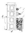
- Fig. 1 3 shows the front view of a basic machine 1.
- the basic machine preferably consists essentially of a sterilization zone 2, a filling machine 3 and a closing machine 4.
- the media preparation 5 is preferably positioned on the roof of the installation 1.
- the treated media are preferably fluids, in particular liquids, such as drinks, flowable foods and the like, as well as auxiliary media such as (sterile) gases, (sterile) water, disinfectants.
- the container treatment plant preferably has a plurality of transfer units 13, at least one container treatment zone 2 for sterilizing the containers, a filling device 3, a closing device 4 and a dry zone along the conveying line F1 between inlet lock 6 and outlet lock 9, wherein preferably a further sterilization chamber 23 is present the closures are fed by gravity of the closing machine 4. It is also conceivable that the container and closure sterilization are arranged in a chamber.
- temperate containers are particularly preferably processed from a container manufacturing machine 19 and a cross table K is docked with several conveyor lines as inlet module 12. It is also conceivable that a cross table K is docked for merging several conveyor lines as outlet module 31.
- the cross table may also preferably be combined with preform sterilization container treatment plants.
- a conveyor line then consists, for example, of preform feed, stretch blow molding machine with preform sterilization module (in front of the heating oven, in the heating oven, between heating oven and blowing wheel or directly in the blowing wheel), cross table, filler, optionally with intermediate transport devices. More preferably, the treatment unit 8 has two sections b / c, in which the containers are treated at different temperatures.
- Fig. 2 shows a plan view of the basic machine of the system, which may for example represent a second container treatment plant.
- a housing in particular an insulator housing 33, there are at least one treatment unit 7 with a treatment fluid, in particular a gas such as H2O2, a treatment unit 8 with at least one further medium such as sterile air, a container filling unit 3 and / or a closure unit 4
- the outlet lock 9 is integrated into the housing. Due to the manufacturing, the insulator housing 33 is limited in length, width and height, therefore, the inlet lock 6 and / or especially the outlet housing may be integrated into the welded part of the housing, but this need not be the case in every embodiment. Because of the carryover of media in the insulator housing 33, the individual treatment units 3/4/7/8 are preferably separated by partitions 14. Transfer units 13 transport the containers from one treatment center to the next.
- the inlet module 12 can be a stretch blow molding machine, a container distribution unit, a container preheating unit or, in the simplest case, a transfer unit, in particular with air transport.
- the insulator housing 33 and its internals may preferably be cleaned with caustic and after a drying phase with a further medium, such as H2O2 gas sterilized.
- a pedestal 11 is preferably present.
- Fig. 3 shows a front view of an advantageous block variant.
- the aseptic system 1 is preferably provided with a stretch blow molding machine 19, e.g. may be a first container handling device, blocked, i. the transport devices are preferably synchronized.
- the preforms are brought to sorting 16 via a feed unit 15. Then they are conveyed via a transport unit, e.g. a chute, actively or passively promoted in the heater 17.
- a transport unit e.g. a chute
- an air rinser (not shown) is preferably installed between the sorting and the heating wheel.
- the containers are shaped and then transferred via a transfer unit to the sterilization and bottling plant.
- FIG. 3 An advantageous arrangement of the shutter 20, is eg in Fig. 3 shown.
- a double cascade it is possible, for example, to provide different, in particular several, for example two or three different types of closure.
- An inspection unit 22 may be provided for checking the closures, in particular for dimensional stability, before the closures are supplied to the closure sterilization chamber 23.
- the closures therefore preferably slide in a channel through the chamber 23 due to their own gravitational pull.
- the oblique arrangement of the chamber (angle of attack of 15-90 °, preferably 25-40 ° and particularly preferably approximately 30 ° or 30 °). treatment time is gained.
- the closures are also treated with at least one gas, in particular H2O2.
- a unit for controlling the closure speed is present on or in the chamber in order to ensure a certain treatment time.
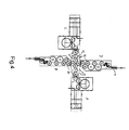
- Fig. 4 shows a block version with cross table to gain more flexibility with very short changeover times.
- containers of a particular shape and size eg, 500ml containers
- machine A containers of a particular shape and size (eg, 500ml containers) can be made.
- machine B can z. B. be a filling machine that fills a drink, such as strawberry juice with red cap.
- Machine C provides z. B. container forth with a different size (eg., 1000ml container) as a machine A.
- the filling machine D fills, for example, another drink, such as grape juice, For example, it closes and closes with a blue shutter.
- the conveyor line F2 represents the container track from the machine C via the cross table to the machine D.
- two end products can be produced, e.g. Grape juice with blue cap in 1000ml container and strawberry juice with red cap in 500ml container.
- the cross table or the transport device is thus preferably composed of the three or four transport stars T 51 , T 52 , T 53 , T 54 , which are particularly preferably each driven by servo motors.
- the transport stars or gripping elements of the transport stars can transfer the transported containers coming from the first treatment device to one of two further transport stars. This is done, for example, such that containers are conveyed via the transport star T 51 to the transport star T 52 . If a production change to be made, so for example, by new or reconfiguration of the controller or the driving of the transport star T 51, T 52, T 53, T 54, the recruitment of new conveyance paths.
- the containers no longer passes to the transport star T 52 , but to the transport star T 54 .
- the production change for the transport star T 53 this then promotes namely the containers no longer to the transport star T 54 , but to the transport star T 52 .
- a production change can also be effected by the transport stars T 51 , T 52 , T 53 , T 54 are rotated in their entirety as a cross table such that, for example, the transport star T 51 assumes the position of the transport star T 54 . It is advantageous that none of the two stretch blow molding machines must be converted to another container, which is usually very time consuming. Furthermore, the filling products can remain in the respective filling machines, so that the filling machines do not have to be rinsed or cleaned / sterilized.
- Fig. 5 shows the easy change of production.
- Machine A now supplies machine D and machine C via conveyor line F3 via conveyor line F4 machine B.
- the final products can then be grape juice with blue cap in 500ml container and strawberry juice with red cap in 1000ml container.
- a cross table K is particularly suitable for systems in the low power range, since usually no buffer distances between the machines are required and the individual machines still occupy relatively small footprint. If hygiene is particularly important during production, the mechanical stage can also be used like the one in Fig. 2 shown machine, automated cleaned and / or sterilized, since it is preferably integrated in the insulator housing. In production, for example, through installed ventilation technology, the housing of the cross table be subjected to an overpressure.
- tank handling units may be installed on the transfer units (T1, T2, T3, T4). It is conceivable that treatments by means such as e.g. a container preheating unit, container sterilization unit or treatments such as e.g. Container cooling, z. As with carbonated drinks, the container identification (dating, bar code) and / or the container labeling are feasible.
- a container ejecting device 24 may expediently be present at the cross table or the transport device.
- a container lock 28 or a lock lock 32 is present on the conveyor lines F1 / F2 or V between the container sterilization 2 or the closure sterilization 23 and the machine outlet 27/31.
- each machine is preferably equipped with one or more servo axes.
- the respective control is preferably carried out by a control unit, not shown, corresponding to a selectable production program.
- the XY stage is S1 / S2 / S3 and S4, as in FIG Fig. 5 shown, equipped.
- the conveyor lines F3 and F4 (or F1 and F2) can be occupied with different production outputs.
- the output of conveyor line F3 can be 12,000 containers per hour with 500ml grape juice and that of conveyor line F4 10,000 containers per hour with 1000ml strawberry juice.
- Fig. 6 shows a further block variant with cross table K.
- each inlet module 12 is installed at the aseptic filling systems B and D.
- the containers are in this example via a respective transport unit, such. an air transporter 26, the system supplied.
- the conveyor lines F1 / F2 converge at the cross table and the containers are then provided with a label in the labeling machine E.
- the aseptic processing machine 1 is blocked with a labeling machine E (with one or more units E1 / E2, etc.).
- the first container treatment device preforms can be formed into bottles, that is, the first container treatment device may be e.g. can be designed as a blowing machine, and with the second container treatment device, the bottles can be filled, that is, that the second container treatment device, for. a filler can be.
- the first container treatment device performs the filling of the bottles or containers and the second container treatment device is a labeling device.
- both conveyor lines preferably produce between 6000 and 18000 containers per hour and more preferably about 12 000 containers per hour.
- both conveyor lines run with the same power.
- a bottle contents corresponding label on the container can be applied.
- the plant controller and / or a scanner 25 ensures that the corresponding label is associated with the container with the corresponding bottle contents. It is conceivable that the containers which are conveyed on the conveyor lines 1 and 2, an identification feature, for. B. in the form of a barcode.
- Every second container then has a different content / closure and label over its direct predecessor. This makes it possible to pack units of two different types in the packaging line.
- a six-pack of 3x grape juice and 3x strawberry juice can be produced.
- Such a system may be referred to, for example, as a 2-color filling system.
- the labeling machine E can be blocked directly to a processing machine 1.
- the sealed containers arc traded over transport stars T n . Since in many cases the closure covers one or more support rings of the containers, the containers can no longer be transported consistently via a gripper system. It is therefore preferable for the containers to be conveyable via transport elements, such as, for example, one or more neck pockets or via a height-adjustable bottom support element. Such a ground support element is in DE102009058084.0 and is incorporated by reference in its entirety into the subject matter of this invention.
- a treatment step (sterilization / filling and / or closing) of one or more containers is not completed.
- Such containers can preferably be taken from the conveyor line F1 or F2 by means of a transport star T4 via a lock 28.
- Detected faulty treatment steps or containers by a sensor that on the conveyor line and / or in the Treatment elements is providable.
- the system controller remembers (for example by means of a shift register) an incorrectly treated container, determines the partner container in the other conveyor line and gives the command to a transport star, such as the transport star T3 or T4, either from T1 to T3 not to take over, or from T1 or T2 to T4.
- An ejector 24 removes the containers from the transport system.
- This system is particularly advantageous for contamination in the downstream machines and plant components, such.
- As the labeling machine E to avoid by not closed container. However, it is also possible to take faulty containers in the conveying direction after the cross table via an ejector from production. Then, instead of the container lock 28, a third aseptic filling installation may be docked. Consequently, preferably the cross table K is equipped with a modified container transport system and the labeling machine E is preferably equipped with three units. It is therefore possible to supplement or expand the system to the 3-color system.
- an intake module 12 is shown, which is fed via an air conveyor 26 with containers.
- This inlet module 12 or any inlet module 12 may preferably be designed as a cross table.
- a container preheating unit 29 may be in use. This has a positive effect on residues, for example in the case of sterilization, such as dry H2O2 sterilization, in particular in the case of plastic containers, such as in PET containers. For other container materials, such. B. HDPE, it is conceivable that can be dispensed preheating the container.
- Container sterilization processes are subject to z. T. also legally regulated country-specific approvals, the z. B. do not provide the preheating of the container.
- the system can be adapted to country-specific requirements.
- the treatment units 3/4/7/8 are limited in size, thus the system performance is eg at a 500ml container at about 12 000 B / h.
- the plant performance can be increased, for example, if the blind spot d partially is occupied to extend the treatment time. About 10 to 15% more power is achievable.
- an overpressure to the environment is to be maintained (for example, p 1 ⁇ p at + 10 Pa) (see Fig. 7 ). This is ensured, for example, via several supply air nozzles Z1 / Z2, etc.
- the supply air for example, in the upper part of the housing attached and the exhaust air A1 / A2, etc., for example, in the lower area.
- process air P1 / P2 is supplied to the system in the production, which also acts in the pressure balance.
- the regulation takes place eg via flaps K and / or via a speed control of the supply air fans.
- At least one pressure sensor and / or a control device monitors that the limit value of p 1 is not undershot.
- the supply air can be processed centrally or decentrally by means of filters, in particular sterilizable filters.
- the exhaust air is preferably connected to a manifold and discharged into the environment.
- a scrubber is also or alternatively providable.
- the insulator sterilization (for example by means of hot H2O2 gas) is carried out via the supply air system.
- the insulator housing 33 is preferably a welded construction made of sheet metal, since this provides optimal microbiological safety.
- the base plate 35 (see Fig. 8 ) consists preferably of at least one bottom plate 37 and at least one roof plate 36.
- the base plate in the longitudinal direction (because of the thermal expansion) provided with stiffeners 38.
- stiffeners 38 are preferably welded into the baseplate.
- the sheets 41 of the insulator housing 33 are preferably attached.
- the housing can also be provided with stiffeners.
- supply and exhaust pipes, and cleaning lines and processes are integrated into the insulator housing. In general, for example, can be used for sealing Usit sealing rings.
- flanges 39 are preferably the bearings for transfer units 13 and / or the treatment units 3/4/7/8.
- Fig. 8 the closing machine 4 is shown. It preferably consists of a bearing 45, which is protected by a sealing device, such as a sealing lip 52, from aggressive substances from the clean room.
- a sealing device such as a sealing lip 52
- On the drive shaft for example, a support plate 47 is fixed, on which in turn the closing elements are mounted or mounted.
- a cam roller 48 preferably moves the casting element 4 up and down.
- a bellows 50 is preferably provided.
- a servo motor 49 is arranged outside the clean room. The rotational movements are usually performed by means of shafts and shaft seal in the clean room. However, a magnetic coupling can also be provided here.
- the torque is preferably transmitted via a power transmission device, such as e.g. a gear pair 51, transferred to the sealing cone.
- a power transmission device such as e.g. a gear pair 51
- Container and closure 44 are transferred to the closing machine 4 via one or more transfer units.
- a closure inspection unit 22 is present between a closure sorting 20 and the closure sterilization chamber 23.
- the containers are arranged on container supports, not shown.
- Fig. 9 is an example of a preferred arrangement of a plurality of interconnected and / or shown at least temporarily or successively or directly or indirectly cooperating devices.
- the number of devices may be less than, equal to or greater than those in Fig. 9 be shown number.
- Fig. 9 arrangement shown is advantageous since the containers can preferably be conveyed upstream and / or downstream, depending on production conditions.
- containers in a first configuration preferably preforms
- the containers in a first configuration can be supplied, for example, to a mechanical stage K, in order subsequently to be conveyed, for example, to one or more container production machines.
- the containers can be supplied for further and / or initial treatment, for example to an aseptic container treatment machine 1.
- the containers can be supplied via a further treatment device, such as a labeling machine E, a packaging or labeling area or device 54.
- a further treatment device such as a labeling machine E, a packaging or labeling area or device 54.
- the packaging or labeling area preferably extends along one side of the part of the installation described above, wherein it is also conceivable that the packaging or labeling area extends on both sides of this part of the installation.
Landscapes
- Engineering & Computer Science (AREA)
- Manufacturing & Machinery (AREA)
- Mechanical Engineering (AREA)
- Filling Of Jars Or Cans And Processes For Cleaning And Sealing Jars (AREA)
Applications Claiming Priority (1)
| Application Number | Priority Date | Filing Date | Title |
|---|---|---|---|
| DE102010027077A DE102010027077A1 (de) | 2010-07-13 | 2010-07-13 | Aseptische Abfüllanlage |
Publications (2)
| Publication Number | Publication Date |
|---|---|
| EP2407417A1 true EP2407417A1 (fr) | 2012-01-18 |
| EP2407417B1 EP2407417B1 (fr) | 2016-06-15 |
Family
ID=44883060
Family Applications (1)
| Application Number | Title | Priority Date | Filing Date |
|---|---|---|---|
| EP11172632.9A Active EP2407417B1 (fr) | 2010-07-13 | 2011-07-05 | Dispositif de conditionnement |
Country Status (3)
| Country | Link |
|---|---|
| EP (1) | EP2407417B1 (fr) |
| CN (1) | CN102372162B (fr) |
| DE (1) | DE102010027077A1 (fr) |
Cited By (15)
| Publication number | Priority date | Publication date | Assignee | Title |
|---|---|---|---|---|
| DE102012221804A1 (de) * | 2012-11-28 | 2014-05-28 | Krones Aktiengesellschaft | Transporteinrichtung und Verfahren zum Transport von Kunststoffbehältnissen oder Vorformlingen |
| DE102013218403A1 (de) * | 2013-09-13 | 2015-03-19 | Krones Ag | Vorrichtung und Verfahren zum Transport von Behältern in einer Behälterbehandlungsanlage |
| WO2016020683A1 (fr) * | 2014-08-05 | 2016-02-11 | William Colton | Système d'inspection optique |
| EP2439048B1 (fr) * | 2010-10-07 | 2016-11-16 | Krones AG | Procédé de traitement d'au moins un récipient dans une installation de traitement de récipients |
| WO2017102539A1 (fr) * | 2015-12-16 | 2017-06-22 | Krones Ag | Machine stérile de moulage par soufflage présentant une évacuation pour des récipients |
| WO2017162630A1 (fr) * | 2016-03-21 | 2017-09-28 | Krones Ag | Dispositif de transport de contenants |
| WO2018185015A1 (fr) * | 2017-04-03 | 2018-10-11 | Sidel Participations | Installation de traitement de recipients et procede de changement de format |
| CN109789939A (zh) * | 2016-09-26 | 2019-05-21 | 大日本印刷株式会社 | 无菌填充机以及无菌填充方法 |
| IT201800005582A1 (it) * | 2018-05-22 | 2019-11-22 | Apparato di riempimento di contenitori in asettico e metodo per sterilizzare tale apparato | |
| CN111891703A (zh) * | 2019-05-06 | 2020-11-06 | 山东智汇环境工程有限公司 | 一种杀菌机 |
| WO2021116364A1 (fr) | 2019-12-13 | 2021-06-17 | Khs Corpoplast Gmbh | Procédé et installation pour fabriquer et traiter des récipients en plastique stériles |
| EP4132855A1 (fr) * | 2020-04-07 | 2023-02-15 | ECS-Engineering Consulting Services | Système d'encartonneuse et procédé d'encartonnage d'un produit |
| EP4137446A1 (fr) * | 2021-08-16 | 2023-02-22 | Krones AG | Dispositif de traitement des récipients pourvu de salle blanche en appui |
| WO2024017551A1 (fr) * | 2022-07-19 | 2024-01-25 | Khs Gmbh | Machine de fermeture et système de remplissage |
| EP4650144A1 (fr) * | 2024-05-14 | 2025-11-19 | KHS GmbH | Procédé et dispositif de traitement sans contamination de récipients dans une machine de traitement |
Families Citing this family (9)
| Publication number | Priority date | Publication date | Assignee | Title |
|---|---|---|---|---|
| CN103318460B (zh) * | 2013-07-16 | 2015-01-14 | 湖南千山制药机械股份有限公司 | 容器的制造装置及方法 |
| CN103420319B (zh) * | 2013-08-27 | 2015-04-29 | 广州达意隆包装机械股份有限公司 | 一种用于灌装不同瓶装饮料的生产线设备 |
| DE102013112091A1 (de) * | 2013-11-04 | 2015-05-07 | Volker Till | Vorrichtung zur Aufgabe und/oder Entnahme von Objekten auf eine und/oder von einer Behandlungsmaschine |
| DE202014009785U1 (de) | 2014-12-12 | 2015-03-09 | Liese Gmbh | Handhabungsanlage für Behälter |
| DE102017120762A1 (de) * | 2017-09-08 | 2019-03-14 | Krones Ag | Flexible Anlage zum Behandeln von Behältnissen |
| DE102017219503A1 (de) | 2017-11-02 | 2019-05-02 | Bausch + Ströbel Maschinenfabrik Ilshofen GmbH + Co. KG | Verstellbares Vakuumrad |
| DE102021133886A1 (de) | 2021-12-20 | 2023-06-22 | Krones Aktiengesellschaft | Vorrichtung zum Transportieren von Behältern und Verfahren zu deren Betrieb |
| DE102022117415A1 (de) * | 2022-07-13 | 2024-01-18 | Khs Gmbh | Schleuse für eine Anlage zum Herstellen und/oder Behandeln von Behältern, Anlage umfassend die Schleuse und Verfahren zum Reinigen und/oder Desinfizieren der Schleuse oder Anlage |
| DE102024115879A1 (de) * | 2024-06-06 | 2025-12-11 | OPTIMA pharma GmbH | Anlage und Verfahren zum Füllen und Verschließen von Objekten in einer sterilen Umgebung |
Citations (12)
| Publication number | Priority date | Publication date | Assignee | Title |
|---|---|---|---|---|
| EP0353534A1 (fr) * | 1988-07-19 | 1990-02-07 | Rudolf Zodrow | Machine de traitement de bouteilles munies de fermeture à étrier, en particulier boucheuse en combinaison avec une étiqueteuse |
| DE4114889A1 (de) * | 1991-05-07 | 1992-11-12 | Kronseder Maschf Krones | Verfahren und vorrichtung zum befuellen und verschliessen von gefaessen |
| WO2000066282A1 (fr) * | 1999-04-30 | 2000-11-09 | B & H Manufacturing Company, Inc. | Appareil de commande a alimentation par tourelle permettant de trier et repartir des articles dans un systeme de traitement |
| EP1251085A1 (fr) * | 2001-04-19 | 2002-10-23 | Dai Nippon Printing Co., Ltd. | Système de transport de vaisseaux |
| DE69622800T2 (de) | 1995-08-11 | 2002-12-05 | Tetra Pak Plastics Ltd., Petit Lancy | Anlage zum sterilen Füllen von Flaschen im Durchlaufverfahren |
| DE102005012507A1 (de) | 2005-03-16 | 2006-09-21 | Krones Ag | Verfahren und Vorrichtung betrefffend das Sterilabfüllen von Flüssigkeiten |
| WO2006097796A2 (fr) * | 2005-03-15 | 2006-09-21 | Sacmi Filling Spa | Systeme permettant d'optimiser l'alimentation en bouteilles dans des installations de remplissage |
| DE102005015565A1 (de) * | 2005-04-05 | 2006-10-12 | Krones Ag | Anlage zum Herstellen und Bearbeiten von Behältern |
| EP1687222B1 (fr) | 2003-11-26 | 2007-07-04 | Krones Aktiengesellschaft | Procede et dispositif pour manipuler des objets |
| EP2082979A1 (fr) * | 2008-01-25 | 2009-07-29 | Shibuya Kogyo Co., Ltd. | Système de traitement d'articles |
| DE102009058084A1 (de) | 2009-12-14 | 2011-06-16 | Krones Ag | Vorrichtung und Verfahren zum Transportieren von Behältnissen mit Bodenführung |
| DE102010021733A1 (de) | 2010-05-27 | 2011-12-01 | Krones Ag | Vorrichtung zum Befüllen von Behältern |
Family Cites Families (10)
| Publication number | Priority date | Publication date | Assignee | Title |
|---|---|---|---|---|
| DE19921274A1 (de) * | 1999-05-07 | 2000-11-09 | Ruediger Haaga Gmbh | Maschinenanlage zum Befüllen von Behältern mit Füllgut |
| DE19928325A1 (de) * | 1999-06-21 | 2000-12-28 | Krones Ag | Abfüllvorrichtung für Flaschen |
| DE29913237U1 (de) * | 1999-08-04 | 2000-12-21 | Autefa Maschinenfabrik GmbH, 86316 Friedberg | Pufferanordnung für Flaschen in einer Flaschenbehandlungsanlage |
| DE10034241A1 (de) * | 2000-07-13 | 2002-02-07 | Krones Ag | Verfahren und Produktionsanlage zum Füllen, Verschließen, Ausstatten und/oder Verpacken von Gefäßen |
| CN1316367A (zh) * | 2001-05-08 | 2001-10-10 | 朱仲力 | 塑料卷材半硬瓶式成组液体包装工艺及其设备 |
| EP1295818B1 (fr) * | 2001-09-20 | 2006-01-25 | Sig Simonazzi S.P.A. | Convoyeur de bouteilles au-dessus duquel sont montés les dispositifs d'entraînement |
| DE202006003690U1 (de) * | 2006-03-09 | 2006-06-14 | Khs Ag | Förderweiche |
| DE102008018516A1 (de) * | 2008-04-12 | 2009-10-15 | Krones Ag | Vorrichtung zum Befüllen von Behältnissen |
| CN201228226Y (zh) * | 2008-05-19 | 2009-04-29 | 湖南千山制药机械股份有限公司 | 旋转式塑料瓶吹洗灌封一体机 |
| DE102008038141B4 (de) * | 2008-08-18 | 2025-03-13 | Krones Aktiengesellschaft | Vorrichtung mit Reinraum zum Umformen von Kunststoffvorformlingen zu Kunststoffbehältnissen und Anlage zum Herstellen von Kunststoffbehältnissen sowie Verfahren zum Umformen von Kunststoffvorformlingen zu Kunststoffbehältnissen |
-
2010
- 2010-07-13 DE DE102010027077A patent/DE102010027077A1/de not_active Withdrawn
-
2011
- 2011-07-05 EP EP11172632.9A patent/EP2407417B1/fr active Active
- 2011-07-07 CN CN201110189190.2A patent/CN102372162B/zh active Active
Patent Citations (12)
| Publication number | Priority date | Publication date | Assignee | Title |
|---|---|---|---|---|
| EP0353534A1 (fr) * | 1988-07-19 | 1990-02-07 | Rudolf Zodrow | Machine de traitement de bouteilles munies de fermeture à étrier, en particulier boucheuse en combinaison avec une étiqueteuse |
| DE4114889A1 (de) * | 1991-05-07 | 1992-11-12 | Kronseder Maschf Krones | Verfahren und vorrichtung zum befuellen und verschliessen von gefaessen |
| DE69622800T2 (de) | 1995-08-11 | 2002-12-05 | Tetra Pak Plastics Ltd., Petit Lancy | Anlage zum sterilen Füllen von Flaschen im Durchlaufverfahren |
| WO2000066282A1 (fr) * | 1999-04-30 | 2000-11-09 | B & H Manufacturing Company, Inc. | Appareil de commande a alimentation par tourelle permettant de trier et repartir des articles dans un systeme de traitement |
| EP1251085A1 (fr) * | 2001-04-19 | 2002-10-23 | Dai Nippon Printing Co., Ltd. | Système de transport de vaisseaux |
| EP1687222B1 (fr) | 2003-11-26 | 2007-07-04 | Krones Aktiengesellschaft | Procede et dispositif pour manipuler des objets |
| WO2006097796A2 (fr) * | 2005-03-15 | 2006-09-21 | Sacmi Filling Spa | Systeme permettant d'optimiser l'alimentation en bouteilles dans des installations de remplissage |
| DE102005012507A1 (de) | 2005-03-16 | 2006-09-21 | Krones Ag | Verfahren und Vorrichtung betrefffend das Sterilabfüllen von Flüssigkeiten |
| DE102005015565A1 (de) * | 2005-04-05 | 2006-10-12 | Krones Ag | Anlage zum Herstellen und Bearbeiten von Behältern |
| EP2082979A1 (fr) * | 2008-01-25 | 2009-07-29 | Shibuya Kogyo Co., Ltd. | Système de traitement d'articles |
| DE102009058084A1 (de) | 2009-12-14 | 2011-06-16 | Krones Ag | Vorrichtung und Verfahren zum Transportieren von Behältnissen mit Bodenführung |
| DE102010021733A1 (de) | 2010-05-27 | 2011-12-01 | Krones Ag | Vorrichtung zum Befüllen von Behältern |
Cited By (28)
| Publication number | Priority date | Publication date | Assignee | Title |
|---|---|---|---|---|
| EP2439048B1 (fr) * | 2010-10-07 | 2016-11-16 | Krones AG | Procédé de traitement d'au moins un récipient dans une installation de traitement de récipients |
| DE102012221804B4 (de) * | 2012-11-28 | 2024-10-24 | Krones Aktiengesellschaft | Transporteinrichtung und Verfahren zum Transport von Kunststoffbehältnissen oder Vorformlingen |
| DE102012221804A1 (de) * | 2012-11-28 | 2014-05-28 | Krones Aktiengesellschaft | Transporteinrichtung und Verfahren zum Transport von Kunststoffbehältnissen oder Vorformlingen |
| DE102013218403A1 (de) * | 2013-09-13 | 2015-03-19 | Krones Ag | Vorrichtung und Verfahren zum Transport von Behältern in einer Behälterbehandlungsanlage |
| US9809392B2 (en) | 2013-09-13 | 2017-11-07 | Krones Ag | Device and method for transporting containers in a container treatment system |
| WO2016020683A1 (fr) * | 2014-08-05 | 2016-02-11 | William Colton | Système d'inspection optique |
| US11472092B2 (en) | 2015-12-16 | 2022-10-18 | Krones Ag | Sterile blow-moulding machine with ejection for containers |
| WO2017102539A1 (fr) * | 2015-12-16 | 2017-06-22 | Krones Ag | Machine stérile de moulage par soufflage présentant une évacuation pour des récipients |
| US10315904B2 (en) | 2016-03-21 | 2019-06-11 | Krones Ag | Device for transporting containers |
| CN107735354A (zh) * | 2016-03-21 | 2018-02-23 | 克罗内斯股份公司 | 用于运输容器的设备 |
| WO2017162630A1 (fr) * | 2016-03-21 | 2017-09-28 | Krones Ag | Dispositif de transport de contenants |
| CN109789939A (zh) * | 2016-09-26 | 2019-05-21 | 大日本印刷株式会社 | 无菌填充机以及无菌填充方法 |
| EP3517451A4 (fr) * | 2016-09-26 | 2020-05-27 | Dai Nippon Printing Co., Ltd. | Machine de remplissage aseptique et procédé de remplissage aseptique |
| CN112678278A (zh) * | 2016-09-26 | 2021-04-20 | 大日本印刷株式会社 | 无菌填充机以及无菌填充方法 |
| EP3835223A1 (fr) * | 2016-09-26 | 2021-06-16 | Dai Nippon Printing Co., Ltd. | Machine et méthode de remplissage asceptisés |
| US11261072B2 (en) | 2016-09-26 | 2022-03-01 | Dai Nippon Printing Co., Ltd. | Aseptic filling machine and aseptic filling method |
| CN112678278B (zh) * | 2016-09-26 | 2022-06-28 | 大日本印刷株式会社 | 无菌填充机以及无菌填充方法 |
| WO2018185015A1 (fr) * | 2017-04-03 | 2018-10-11 | Sidel Participations | Installation de traitement de recipients et procede de changement de format |
| IT201800005582A1 (it) * | 2018-05-22 | 2019-11-22 | Apparato di riempimento di contenitori in asettico e metodo per sterilizzare tale apparato | |
| WO2019224625A1 (fr) * | 2018-05-22 | 2019-11-28 | Gea Procomac S.P.A. | Appareil de remplissage pour remplir des récipients dans des conditions aseptiques et procédé de stérilisation d'un tel appareil |
| CN111891703A (zh) * | 2019-05-06 | 2020-11-06 | 山东智汇环境工程有限公司 | 一种杀菌机 |
| CN111891703B (zh) * | 2019-05-06 | 2023-09-19 | 山东智汇环境工程有限公司 | 一种杀菌机 |
| WO2021116364A1 (fr) | 2019-12-13 | 2021-06-17 | Khs Corpoplast Gmbh | Procédé et installation pour fabriquer et traiter des récipients en plastique stériles |
| EP4132855A1 (fr) * | 2020-04-07 | 2023-02-15 | ECS-Engineering Consulting Services | Système d'encartonneuse et procédé d'encartonnage d'un produit |
| US12139290B2 (en) | 2020-04-07 | 2024-11-12 | Ecs-Engineering Consulting Services | Cartoning machine system and method for cartoning a product |
| EP4137446A1 (fr) * | 2021-08-16 | 2023-02-22 | Krones AG | Dispositif de traitement des récipients pourvu de salle blanche en appui |
| WO2024017551A1 (fr) * | 2022-07-19 | 2024-01-25 | Khs Gmbh | Machine de fermeture et système de remplissage |
| EP4650144A1 (fr) * | 2024-05-14 | 2025-11-19 | KHS GmbH | Procédé et dispositif de traitement sans contamination de récipients dans une machine de traitement |
Also Published As
| Publication number | Publication date |
|---|---|
| DE102010027077A1 (de) | 2012-01-19 |
| EP2407417B1 (fr) | 2016-06-15 |
| CN102372162B (zh) | 2015-05-27 |
| CN102372162A (zh) | 2012-03-14 |
Similar Documents
| Publication | Publication Date | Title |
|---|---|---|
| EP2407417B1 (fr) | Dispositif de conditionnement | |
| DE102009041160B4 (de) | Vorrichtung zum Herstellen von Flüssigkeitsbehältnissen | |
| EP2292550B1 (fr) | Dispositif et procédé de fabrication de bouteilles en plastique | |
| EP2001774B1 (fr) | Systeme de transport de bouteilles ou de recipients similaires et installation de traitement de bouteilles ou de recipients similaires | |
| EP4063313B1 (fr) | Installation de remplissage en bouteille aseptique de produits liquides | |
| EP2043944B1 (fr) | Machine de manipulation | |
| DE102013014618B4 (de) | Synchronlaufsicherung für Übergabestationen für Vorrichtungen zum Handhaben von Behältern | |
| EP2460746B1 (fr) | Dispositif de transport pour récipients | |
| EP2125583B1 (fr) | Installation de traitement de bouteilles | |
| EP2885240B1 (fr) | Système de transport en étoile pour contenants, parcours de transport de contenants et installation de traitement de contenants | |
| DE102012217457A1 (de) | Förderabschnitt mit rotierendem einteil- und/oder förderstern zur herstellung eines teilungsverzugs zwischen aufeinander folgenden behältern | |
| EP4001209A1 (fr) | Installation de remplissage pour produits liquides et procédé de remplissage de bouteilles des produits liquides | |
| DE102010018216B4 (de) | Behältnisbehandlungsanlage mit änderbarer Beladung | |
| WO2011131704A1 (fr) | Dispositif de transport et procédé de transport pour installation de traitement de contenants, et installation de traitement de contenants dotée d'un tel dispositif de transport | |
| EP2361835B2 (fr) | Dispositif et procédé destinés à l'étiquetage de récipients remplis | |
| DE102005015565A1 (de) | Anlage zum Herstellen und Bearbeiten von Behältern | |
| EP2361874B1 (fr) | Installation de formation et de traitement de récipient | |
| DE102010021733A1 (de) | Vorrichtung zum Befüllen von Behältern | |
| EP4508000A1 (fr) | Système de traitement de récipients | |
| EP4508001A1 (fr) | Système de traitement de récipients | |
| DE102021127132A1 (de) | Führungseinrichtung zum Führen von transportierten Behältern | |
| EP4494838B1 (fr) | Dispositif d'accouplement d'une machine de fabrication et machine d'étirage-soufflage par transport d'air | |
| EP4653385A1 (fr) | Installation de traitement de boîtes et procédé de traitement de boîtes | |
| WO2025016586A1 (fr) | Dispositif de poussée pour préformes | |
| EP4653174A1 (fr) | Dispositif de transfert pour le transport sans contamination de récipients dans un dispositif de traitement de récipients |
Legal Events
| Date | Code | Title | Description |
|---|---|---|---|
| AK | Designated contracting states |
Kind code of ref document: A1 Designated state(s): AL AT BE BG CH CY CZ DE DK EE ES FI FR GB GR HR HU IE IS IT LI LT LU LV MC MK MT NL NO PL PT RO RS SE SI SK SM TR |
|
| AX | Request for extension of the european patent |
Extension state: BA ME |
|
| PUAI | Public reference made under article 153(3) epc to a published international application that has entered the european phase |
Free format text: ORIGINAL CODE: 0009012 |
|
| 17P | Request for examination filed |
Effective date: 20120716 |
|
| GRAP | Despatch of communication of intention to grant a patent |
Free format text: ORIGINAL CODE: EPIDOSNIGR1 |
|
| INTG | Intention to grant announced |
Effective date: 20160104 |
|
| GRAS | Grant fee paid |
Free format text: ORIGINAL CODE: EPIDOSNIGR3 |
|
| GRAA | (expected) grant |
Free format text: ORIGINAL CODE: 0009210 |
|
| AK | Designated contracting states |
Kind code of ref document: B1 Designated state(s): AL AT BE BG CH CY CZ DE DK EE ES FI FR GB GR HR HU IE IS IT LI LT LU LV MC MK MT NL NO PL PT RO RS SE SI SK SM TR |
|
| REG | Reference to a national code |
Ref country code: CH Ref legal event code: EP Ref country code: GB Ref legal event code: FG4D Free format text: NOT ENGLISH |
|
| REG | Reference to a national code |
Ref country code: IE Ref legal event code: FG4D Free format text: LANGUAGE OF EP DOCUMENT: GERMAN |
|
| REG | Reference to a national code |
Ref country code: AT Ref legal event code: REF Ref document number: 806417 Country of ref document: AT Kind code of ref document: T Effective date: 20160715 |
|
| REG | Reference to a national code |
Ref country code: DE Ref legal event code: R096 Ref document number: 502011009961 Country of ref document: DE |
|
| REG | Reference to a national code |
Ref country code: LT Ref legal event code: MG4D |
|
| REG | Reference to a national code |
Ref country code: NL Ref legal event code: MP Effective date: 20160615 |
|
| PG25 | Lapsed in a contracting state [announced via postgrant information from national office to epo] |
Ref country code: LT Free format text: LAPSE BECAUSE OF FAILURE TO SUBMIT A TRANSLATION OF THE DESCRIPTION OR TO PAY THE FEE WITHIN THE PRESCRIBED TIME-LIMIT Effective date: 20160615 Ref country code: NO Free format text: LAPSE BECAUSE OF FAILURE TO SUBMIT A TRANSLATION OF THE DESCRIPTION OR TO PAY THE FEE WITHIN THE PRESCRIBED TIME-LIMIT Effective date: 20160915 Ref country code: FI Free format text: LAPSE BECAUSE OF FAILURE TO SUBMIT A TRANSLATION OF THE DESCRIPTION OR TO PAY THE FEE WITHIN THE PRESCRIBED TIME-LIMIT Effective date: 20160615 |
|
| PG25 | Lapsed in a contracting state [announced via postgrant information from national office to epo] |
Ref country code: SE Free format text: LAPSE BECAUSE OF FAILURE TO SUBMIT A TRANSLATION OF THE DESCRIPTION OR TO PAY THE FEE WITHIN THE PRESCRIBED TIME-LIMIT Effective date: 20160615 Ref country code: RS Free format text: LAPSE BECAUSE OF FAILURE TO SUBMIT A TRANSLATION OF THE DESCRIPTION OR TO PAY THE FEE WITHIN THE PRESCRIBED TIME-LIMIT Effective date: 20160615 Ref country code: HR Free format text: LAPSE BECAUSE OF FAILURE TO SUBMIT A TRANSLATION OF THE DESCRIPTION OR TO PAY THE FEE WITHIN THE PRESCRIBED TIME-LIMIT Effective date: 20160615 Ref country code: GR Free format text: LAPSE BECAUSE OF FAILURE TO SUBMIT A TRANSLATION OF THE DESCRIPTION OR TO PAY THE FEE WITHIN THE PRESCRIBED TIME-LIMIT Effective date: 20160916 Ref country code: LV Free format text: LAPSE BECAUSE OF FAILURE TO SUBMIT A TRANSLATION OF THE DESCRIPTION OR TO PAY THE FEE WITHIN THE PRESCRIBED TIME-LIMIT Effective date: 20160615 Ref country code: NL Free format text: LAPSE BECAUSE OF FAILURE TO SUBMIT A TRANSLATION OF THE DESCRIPTION OR TO PAY THE FEE WITHIN THE PRESCRIBED TIME-LIMIT Effective date: 20160615 |
|
| PG25 | Lapsed in a contracting state [announced via postgrant information from national office to epo] |
Ref country code: BE Free format text: LAPSE BECAUSE OF NON-PAYMENT OF DUE FEES Effective date: 20160731 |
|
| PG25 | Lapsed in a contracting state [announced via postgrant information from national office to epo] |
Ref country code: CZ Free format text: LAPSE BECAUSE OF FAILURE TO SUBMIT A TRANSLATION OF THE DESCRIPTION OR TO PAY THE FEE WITHIN THE PRESCRIBED TIME-LIMIT Effective date: 20160615 Ref country code: SK Free format text: LAPSE BECAUSE OF FAILURE TO SUBMIT A TRANSLATION OF THE DESCRIPTION OR TO PAY THE FEE WITHIN THE PRESCRIBED TIME-LIMIT Effective date: 20160615 Ref country code: RO Free format text: LAPSE BECAUSE OF FAILURE TO SUBMIT A TRANSLATION OF THE DESCRIPTION OR TO PAY THE FEE WITHIN THE PRESCRIBED TIME-LIMIT Effective date: 20160615 Ref country code: IS Free format text: LAPSE BECAUSE OF FAILURE TO SUBMIT A TRANSLATION OF THE DESCRIPTION OR TO PAY THE FEE WITHIN THE PRESCRIBED TIME-LIMIT Effective date: 20161015 Ref country code: EE Free format text: LAPSE BECAUSE OF FAILURE TO SUBMIT A TRANSLATION OF THE DESCRIPTION OR TO PAY THE FEE WITHIN THE PRESCRIBED TIME-LIMIT Effective date: 20160615 Ref country code: IT Free format text: LAPSE BECAUSE OF FAILURE TO SUBMIT A TRANSLATION OF THE DESCRIPTION OR TO PAY THE FEE WITHIN THE PRESCRIBED TIME-LIMIT Effective date: 20160615 |
|
| PG25 | Lapsed in a contracting state [announced via postgrant information from national office to epo] |
Ref country code: PL Free format text: LAPSE BECAUSE OF FAILURE TO SUBMIT A TRANSLATION OF THE DESCRIPTION OR TO PAY THE FEE WITHIN THE PRESCRIBED TIME-LIMIT Effective date: 20160615 Ref country code: ES Free format text: LAPSE BECAUSE OF FAILURE TO SUBMIT A TRANSLATION OF THE DESCRIPTION OR TO PAY THE FEE WITHIN THE PRESCRIBED TIME-LIMIT Effective date: 20160615 Ref country code: SM Free format text: LAPSE BECAUSE OF FAILURE TO SUBMIT A TRANSLATION OF THE DESCRIPTION OR TO PAY THE FEE WITHIN THE PRESCRIBED TIME-LIMIT Effective date: 20160615 Ref country code: PT Free format text: LAPSE BECAUSE OF FAILURE TO SUBMIT A TRANSLATION OF THE DESCRIPTION OR TO PAY THE FEE WITHIN THE PRESCRIBED TIME-LIMIT Effective date: 20161017 |
|
| REG | Reference to a national code |
Ref country code: CH Ref legal event code: PL |
|
| REG | Reference to a national code |
Ref country code: DE Ref legal event code: R097 Ref document number: 502011009961 Country of ref document: DE |
|
| PG25 | Lapsed in a contracting state [announced via postgrant information from national office to epo] |
Ref country code: MC Free format text: LAPSE BECAUSE OF FAILURE TO SUBMIT A TRANSLATION OF THE DESCRIPTION OR TO PAY THE FEE WITHIN THE PRESCRIBED TIME-LIMIT Effective date: 20160615 |
|
| PLBE | No opposition filed within time limit |
Free format text: ORIGINAL CODE: 0009261 |
|
| STAA | Information on the status of an ep patent application or granted ep patent |
Free format text: STATUS: NO OPPOSITION FILED WITHIN TIME LIMIT |
|
| PG25 | Lapsed in a contracting state [announced via postgrant information from national office to epo] |
Ref country code: LI Free format text: LAPSE BECAUSE OF NON-PAYMENT OF DUE FEES Effective date: 20160731 Ref country code: FR Free format text: LAPSE BECAUSE OF NON-PAYMENT OF DUE FEES Effective date: 20160816 Ref country code: CH Free format text: LAPSE BECAUSE OF NON-PAYMENT OF DUE FEES Effective date: 20160731 |
|
| REG | Reference to a national code |
Ref country code: FR Ref legal event code: ST Effective date: 20170331 |
|
| REG | Reference to a national code |
Ref country code: IE Ref legal event code: MM4A |
|
| 26N | No opposition filed |
Effective date: 20170316 |
|
| GBPC | Gb: european patent ceased through non-payment of renewal fee |
Effective date: 20160915 |
|
| PG25 | Lapsed in a contracting state [announced via postgrant information from national office to epo] |
Ref country code: DK Free format text: LAPSE BECAUSE OF FAILURE TO SUBMIT A TRANSLATION OF THE DESCRIPTION OR TO PAY THE FEE WITHIN THE PRESCRIBED TIME-LIMIT Effective date: 20160615 |
|
| PG25 | Lapsed in a contracting state [announced via postgrant information from national office to epo] |
Ref country code: IE Free format text: LAPSE BECAUSE OF NON-PAYMENT OF DUE FEES Effective date: 20160705 Ref country code: GB Free format text: LAPSE BECAUSE OF NON-PAYMENT OF DUE FEES Effective date: 20160915 |
|
| PG25 | Lapsed in a contracting state [announced via postgrant information from national office to epo] |
Ref country code: SI Free format text: LAPSE BECAUSE OF FAILURE TO SUBMIT A TRANSLATION OF THE DESCRIPTION OR TO PAY THE FEE WITHIN THE PRESCRIBED TIME-LIMIT Effective date: 20160615 Ref country code: LU Free format text: LAPSE BECAUSE OF NON-PAYMENT OF DUE FEES Effective date: 20160705 |
|
| REG | Reference to a national code |
Ref country code: AT Ref legal event code: MM01 Ref document number: 806417 Country of ref document: AT Kind code of ref document: T Effective date: 20160705 |
|
| PG25 | Lapsed in a contracting state [announced via postgrant information from national office to epo] |
Ref country code: AT Free format text: LAPSE BECAUSE OF NON-PAYMENT OF DUE FEES Effective date: 20160705 |
|
| PG25 | Lapsed in a contracting state [announced via postgrant information from national office to epo] |
Ref country code: HU Free format text: LAPSE BECAUSE OF FAILURE TO SUBMIT A TRANSLATION OF THE DESCRIPTION OR TO PAY THE FEE WITHIN THE PRESCRIBED TIME-LIMIT; INVALID AB INITIO Effective date: 20110705 Ref country code: CY Free format text: LAPSE BECAUSE OF FAILURE TO SUBMIT A TRANSLATION OF THE DESCRIPTION OR TO PAY THE FEE WITHIN THE PRESCRIBED TIME-LIMIT Effective date: 20160615 |
|
| PG25 | Lapsed in a contracting state [announced via postgrant information from national office to epo] |
Ref country code: MK Free format text: LAPSE BECAUSE OF FAILURE TO SUBMIT A TRANSLATION OF THE DESCRIPTION OR TO PAY THE FEE WITHIN THE PRESCRIBED TIME-LIMIT Effective date: 20160615 Ref country code: TR Free format text: LAPSE BECAUSE OF FAILURE TO SUBMIT A TRANSLATION OF THE DESCRIPTION OR TO PAY THE FEE WITHIN THE PRESCRIBED TIME-LIMIT Effective date: 20160615 Ref country code: MT Free format text: LAPSE BECAUSE OF FAILURE TO SUBMIT A TRANSLATION OF THE DESCRIPTION OR TO PAY THE FEE WITHIN THE PRESCRIBED TIME-LIMIT Effective date: 20160615 |
|
| PG25 | Lapsed in a contracting state [announced via postgrant information from national office to epo] |
Ref country code: BG Free format text: LAPSE BECAUSE OF FAILURE TO SUBMIT A TRANSLATION OF THE DESCRIPTION OR TO PAY THE FEE WITHIN THE PRESCRIBED TIME-LIMIT Effective date: 20160615 |
|
| PG25 | Lapsed in a contracting state [announced via postgrant information from national office to epo] |
Ref country code: AL Free format text: LAPSE BECAUSE OF FAILURE TO SUBMIT A TRANSLATION OF THE DESCRIPTION OR TO PAY THE FEE WITHIN THE PRESCRIBED TIME-LIMIT Effective date: 20160615 |
|
| P01 | Opt-out of the competence of the unified patent court (upc) registered |
Effective date: 20230523 |
|
| PGFP | Annual fee paid to national office [announced via postgrant information from national office to epo] |
Ref country code: DE Payment date: 20250604 Year of fee payment: 15 |