EP2408086A2 - Agencement d'accumulation d'énergie - Google Patents
Agencement d'accumulation d'énergie Download PDFInfo
- Publication number
- EP2408086A2 EP2408086A2 EP11161438A EP11161438A EP2408086A2 EP 2408086 A2 EP2408086 A2 EP 2408086A2 EP 11161438 A EP11161438 A EP 11161438A EP 11161438 A EP11161438 A EP 11161438A EP 2408086 A2 EP2408086 A2 EP 2408086A2
- Authority
- EP
- European Patent Office
- Prior art keywords
- memory
- energy storage
- module
- storage device
- cell
- Prior art date
- Legal status (The legal status is an assumption and is not a legal conclusion. Google has not performed a legal analysis and makes no representation as to the accuracy of the status listed.)
- Granted
Links
Images


Classifications
-
- B—PERFORMING OPERATIONS; TRANSPORTING
- B60—VEHICLES IN GENERAL
- B60L—PROPULSION OF ELECTRICALLY-PROPELLED VEHICLES; SUPPLYING ELECTRIC POWER FOR AUXILIARY EQUIPMENT OF ELECTRICALLY-PROPELLED VEHICLES; ELECTRODYNAMIC BRAKE SYSTEMS FOR VEHICLES IN GENERAL; MAGNETIC SUSPENSION OR LEVITATION FOR VEHICLES; MONITORING OPERATING VARIABLES OF ELECTRICALLY-PROPELLED VEHICLES; ELECTRIC SAFETY DEVICES FOR ELECTRICALLY-PROPELLED VEHICLES
- B60L58/00—Methods or circuit arrangements for monitoring or controlling batteries or fuel cells, specially adapted for electric vehicles
- B60L58/10—Methods or circuit arrangements for monitoring or controlling batteries or fuel cells, specially adapted for electric vehicles for monitoring or controlling batteries
- B60L58/12—Methods or circuit arrangements for monitoring or controlling batteries or fuel cells, specially adapted for electric vehicles for monitoring or controlling batteries responding to state of charge [SoC]
- B60L58/13—Maintaining the SoC within a determined range
-
- B—PERFORMING OPERATIONS; TRANSPORTING
- B60—VEHICLES IN GENERAL
- B60L—PROPULSION OF ELECTRICALLY-PROPELLED VEHICLES; SUPPLYING ELECTRIC POWER FOR AUXILIARY EQUIPMENT OF ELECTRICALLY-PROPELLED VEHICLES; ELECTRODYNAMIC BRAKE SYSTEMS FOR VEHICLES IN GENERAL; MAGNETIC SUSPENSION OR LEVITATION FOR VEHICLES; MONITORING OPERATING VARIABLES OF ELECTRICALLY-PROPELLED VEHICLES; ELECTRIC SAFETY DEVICES FOR ELECTRICALLY-PROPELLED VEHICLES
- B60L58/00—Methods or circuit arrangements for monitoring or controlling batteries or fuel cells, specially adapted for electric vehicles
- B60L58/10—Methods or circuit arrangements for monitoring or controlling batteries or fuel cells, specially adapted for electric vehicles for monitoring or controlling batteries
- B60L58/18—Methods or circuit arrangements for monitoring or controlling batteries or fuel cells, specially adapted for electric vehicles for monitoring or controlling batteries of two or more battery modules
- B60L58/22—Balancing the charge of battery modules
-
- B—PERFORMING OPERATIONS; TRANSPORTING
- B60—VEHICLES IN GENERAL
- B60L—PROPULSION OF ELECTRICALLY-PROPELLED VEHICLES; SUPPLYING ELECTRIC POWER FOR AUXILIARY EQUIPMENT OF ELECTRICALLY-PROPELLED VEHICLES; ELECTRODYNAMIC BRAKE SYSTEMS FOR VEHICLES IN GENERAL; MAGNETIC SUSPENSION OR LEVITATION FOR VEHICLES; MONITORING OPERATING VARIABLES OF ELECTRICALLY-PROPELLED VEHICLES; ELECTRIC SAFETY DEVICES FOR ELECTRICALLY-PROPELLED VEHICLES
- B60L58/00—Methods or circuit arrangements for monitoring or controlling batteries or fuel cells, specially adapted for electric vehicles
- B60L58/10—Methods or circuit arrangements for monitoring or controlling batteries or fuel cells, specially adapted for electric vehicles for monitoring or controlling batteries
- B60L58/24—Methods or circuit arrangements for monitoring or controlling batteries or fuel cells, specially adapted for electric vehicles for monitoring or controlling batteries for controlling the temperature of batteries
- B60L58/26—Methods or circuit arrangements for monitoring or controlling batteries or fuel cells, specially adapted for electric vehicles for monitoring or controlling batteries for controlling the temperature of batteries by cooling
-
- H—ELECTRICITY
- H01—ELECTRIC ELEMENTS
- H01G—CAPACITORS; CAPACITORS, RECTIFIERS, DETECTORS, SWITCHING DEVICES, LIGHT-SENSITIVE OR TEMPERATURE-SENSITIVE DEVICES OF THE ELECTROLYTIC TYPE
- H01G11/00—Hybrid capacitors, i.e. capacitors having different positive and negative electrodes; Electric double-layer [EDL] capacitors; Processes for the manufacture thereof or of parts thereof
- H01G11/08—Structural combinations, e.g. assembly or connection, of hybrid or EDL capacitors with other electric components, at least one hybrid or EDL capacitor being the main component
-
- H—ELECTRICITY
- H01—ELECTRIC ELEMENTS
- H01G—CAPACITORS; CAPACITORS, RECTIFIERS, DETECTORS, SWITCHING DEVICES, LIGHT-SENSITIVE OR TEMPERATURE-SENSITIVE DEVICES OF THE ELECTROLYTIC TYPE
- H01G11/00—Hybrid capacitors, i.e. capacitors having different positive and negative electrodes; Electric double-layer [EDL] capacitors; Processes for the manufacture thereof or of parts thereof
- H01G11/10—Multiple hybrid or EDL capacitors, e.g. arrays or modules
-
- H—ELECTRICITY
- H01—ELECTRIC ELEMENTS
- H01G—CAPACITORS; CAPACITORS, RECTIFIERS, DETECTORS, SWITCHING DEVICES, LIGHT-SENSITIVE OR TEMPERATURE-SENSITIVE DEVICES OF THE ELECTROLYTIC TYPE
- H01G11/00—Hybrid capacitors, i.e. capacitors having different positive and negative electrodes; Electric double-layer [EDL] capacitors; Processes for the manufacture thereof or of parts thereof
- H01G11/14—Arrangements or processes for adjusting or protecting hybrid or EDL capacitors
-
- H—ELECTRICITY
- H01—ELECTRIC ELEMENTS
- H01G—CAPACITORS; CAPACITORS, RECTIFIERS, DETECTORS, SWITCHING DEVICES, LIGHT-SENSITIVE OR TEMPERATURE-SENSITIVE DEVICES OF THE ELECTROLYTIC TYPE
- H01G9/00—Electrolytic capacitors, rectifiers, detectors, switching devices, light-sensitive or temperature-sensitive devices; Processes of their manufacture
- H01G9/26—Structural combinations of electrolytic capacitors, rectifiers, detectors, switching devices, light-sensitive or temperature-sensitive devices with each other
-
- H—ELECTRICITY
- H02—GENERATION; CONVERSION OR DISTRIBUTION OF ELECTRIC POWER
- H02J—ELECTRIC POWER NETWORKS; CIRCUIT ARRANGEMENTS OR SYSTEMS FOR SUPPLYING OR DISTRIBUTING ELECTRIC POWER; SYSTEMS FOR STORING ELECTRIC ENERGY
- H02J7/00—Circuit arrangements for charging or discharging batteries or for supplying loads from batteries
- H02J7/50—Circuit arrangements for charging or discharging batteries or for supplying loads from batteries acting upon multiple batteries simultaneously or sequentially
- H02J7/52—Circuit arrangements for charging or discharging batteries or for supplying loads from batteries acting upon multiple batteries simultaneously or sequentially for charge balancing, e.g. equalisation of charge between batteries
- H02J7/54—Passive balancing, e.g. using resistors or parallel MOSFETs
-
- B—PERFORMING OPERATIONS; TRANSPORTING
- B60—VEHICLES IN GENERAL
- B60L—PROPULSION OF ELECTRICALLY-PROPELLED VEHICLES; SUPPLYING ELECTRIC POWER FOR AUXILIARY EQUIPMENT OF ELECTRICALLY-PROPELLED VEHICLES; ELECTRODYNAMIC BRAKE SYSTEMS FOR VEHICLES IN GENERAL; MAGNETIC SUSPENSION OR LEVITATION FOR VEHICLES; MONITORING OPERATING VARIABLES OF ELECTRICALLY-PROPELLED VEHICLES; ELECTRIC SAFETY DEVICES FOR ELECTRICALLY-PROPELLED VEHICLES
- B60L2240/00—Control parameters of input or output; Target parameters
- B60L2240/40—Drive Train control parameters
- B60L2240/54—Drive Train control parameters related to batteries
- B60L2240/545—Temperature
-
- B—PERFORMING OPERATIONS; TRANSPORTING
- B60—VEHICLES IN GENERAL
- B60L—PROPULSION OF ELECTRICALLY-PROPELLED VEHICLES; SUPPLYING ELECTRIC POWER FOR AUXILIARY EQUIPMENT OF ELECTRICALLY-PROPELLED VEHICLES; ELECTRODYNAMIC BRAKE SYSTEMS FOR VEHICLES IN GENERAL; MAGNETIC SUSPENSION OR LEVITATION FOR VEHICLES; MONITORING OPERATING VARIABLES OF ELECTRICALLY-PROPELLED VEHICLES; ELECTRIC SAFETY DEVICES FOR ELECTRICALLY-PROPELLED VEHICLES
- B60L2240/00—Control parameters of input or output; Target parameters
- B60L2240/40—Drive Train control parameters
- B60L2240/54—Drive Train control parameters related to batteries
- B60L2240/547—Voltage
-
- B—PERFORMING OPERATIONS; TRANSPORTING
- B60—VEHICLES IN GENERAL
- B60L—PROPULSION OF ELECTRICALLY-PROPELLED VEHICLES; SUPPLYING ELECTRIC POWER FOR AUXILIARY EQUIPMENT OF ELECTRICALLY-PROPELLED VEHICLES; ELECTRODYNAMIC BRAKE SYSTEMS FOR VEHICLES IN GENERAL; MAGNETIC SUSPENSION OR LEVITATION FOR VEHICLES; MONITORING OPERATING VARIABLES OF ELECTRICALLY-PROPELLED VEHICLES; ELECTRIC SAFETY DEVICES FOR ELECTRICALLY-PROPELLED VEHICLES
- B60L2240/00—Control parameters of input or output; Target parameters
- B60L2240/40—Drive Train control parameters
- B60L2240/54—Drive Train control parameters related to batteries
- B60L2240/549—Current
-
- H—ELECTRICITY
- H02—GENERATION; CONVERSION OR DISTRIBUTION OF ELECTRIC POWER
- H02J—ELECTRIC POWER NETWORKS; CIRCUIT ARRANGEMENTS OR SYSTEMS FOR SUPPLYING OR DISTRIBUTING ELECTRIC POWER; SYSTEMS FOR STORING ELECTRIC ENERGY
- H02J7/00—Circuit arrangements for charging or discharging batteries or for supplying loads from batteries
- H02J7/34—Parallel operation in networks using both storage and other DC sources, e.g. providing buffering
- H02J7/345—Parallel operation in networks using both storage and other DC sources, e.g. providing buffering using capacitors as storage or buffering devices
-
- Y—GENERAL TAGGING OF NEW TECHNOLOGICAL DEVELOPMENTS; GENERAL TAGGING OF CROSS-SECTIONAL TECHNOLOGIES SPANNING OVER SEVERAL SECTIONS OF THE IPC; TECHNICAL SUBJECTS COVERED BY FORMER USPC CROSS-REFERENCE ART COLLECTIONS [XRACs] AND DIGESTS
- Y02—TECHNOLOGIES OR APPLICATIONS FOR MITIGATION OR ADAPTATION AGAINST CLIMATE CHANGE
- Y02E—REDUCTION OF GREENHOUSE GAS [GHG] EMISSIONS, RELATED TO ENERGY GENERATION, TRANSMISSION OR DISTRIBUTION
- Y02E60/00—Enabling technologies; Technologies with a potential or indirect contribution to GHG emissions mitigation
- Y02E60/13—Energy storage using capacitors
-
- Y—GENERAL TAGGING OF NEW TECHNOLOGICAL DEVELOPMENTS; GENERAL TAGGING OF CROSS-SECTIONAL TECHNOLOGIES SPANNING OVER SEVERAL SECTIONS OF THE IPC; TECHNICAL SUBJECTS COVERED BY FORMER USPC CROSS-REFERENCE ART COLLECTIONS [XRACs] AND DIGESTS
- Y02—TECHNOLOGIES OR APPLICATIONS FOR MITIGATION OR ADAPTATION AGAINST CLIMATE CHANGE
- Y02T—CLIMATE CHANGE MITIGATION TECHNOLOGIES RELATED TO TRANSPORTATION
- Y02T10/00—Road transport of goods or passengers
- Y02T10/60—Other road transportation technologies with climate change mitigation effect
- Y02T10/70—Energy storage systems for electromobility, e.g. batteries
Definitions
- the invention relates to an energy storage device having at least two memory modules connected in series electrically, each having a plurality of electrically connected in series memory cells.
- Such memory modules have accumulator cells or double-layer capacitors as memory cells.
- Accumulators and double-layer capacitors are rechargeable charge storage devices that can provide electrical power to a load when charged.
- the voltage at which this power is provided depends on the nature of the charge storage. For lithium-ion batteries this voltage is in the range of about 3.3V and for double-layer capacitors at about 2.5V.
- To supply loads that require higher supply voltages it is known to connect several memory cells in series to a memory cell array. The supply voltage provided by such a memory cell arrangement corresponds to the sum of the individual cell voltages of the series-connected memory cells.
- a uniform, also referred to as symmetrical voltage distribution of the memory cells of a memory module must be achieved by charge equalization.
- the supply voltage exceeds the voltage of a memory module.
- a required Supply voltage which is much higher than the voltage of a memory module
- several memory modules must be electrically connected in series. This also applies to a high-voltage arrangement, for example in trams.
- a plurality of memory modules are electrically connected in series, each memory module having a plurality of memory cells electrically connected in series.
- m memory modules in addition to the balancing of the n memory cells of each of the m memory modules, it is also necessary to balance the m memory modules with one another.
- dissipative memory cells of a memory module are discharged by converting part of their stored charge into heat, for example in ohmic resistances.
- regenerative processes excess energy or charge of individual memory cells of a memory module is redistributed to other memory cells of this memory module.
- Dissipative methods are known, for example, from Analog Devices' Lithium Ion Battery Monitoring System AD7280, 2008, and from Linear Technology's 2009 Multicell Battery Stack Monitor LTC6802-1.
- the plurality of memory modules of an energy storage arrangement can also be balanced with one another by discharging entire modules by converting energy stored in all of their n memory cells into heat at the same time.
- the disadvantage here is the high heat output incurred whose derivation from the individual memory modules causes problems.
- the regenerative processes are again subdivided into inductive methods, which can be found, for example, in "PowerLAN TM Dual-Cell Li-ion Battery Monitor with PowerPump TM Cell Balancing". from Texas Instruments, 2009, and from the DE 102008021090 A1 and capacitive techniques known, for example, from the EPE publication, Barcelona 2009, entitled “Analysis and Improvements of Novel Voltage Balancers for Electric Double Layer Capacitor Employing a CW circuit". Symmetrization of m memory modules of an energy storage arrangement with each other is possible in the regenerative process only using additional high voltage cable between the m memory modules and the terminals of the energy storage device, which means a considerable additional effort.
- the invention is based on the object of further developing an energy storage arrangement having a plurality of memory modules such that no additional high-voltage cables are required when an inductive regenerative balancing method is used.
- the inductive module memory elements of each memory module are electrically connected in parallel to the series connection of its memory cells and each memory module has a series connection of a power resistor and a module switch, said series each electrically parallel to the series connection of the memory cells of a Memory module is switched.
- a power resistor By means of this power resistor, in each case a memory module of an energy storage arrangement can be discharged as a whole, whereby the memory modules of an energy storage arrangement are symmetrized in several steps.
- the memory modules of an energy storage device are balanced with each other, without that these memory modules must be interconnected by means of high voltage cables to terminals of the energy storage device. The occurring heat loss of each memory module falls then each at its power resistor, from where it can be easily dissipated.
- FIG. 1 An energy storage device 2 for high voltage applications is schematically shown in FIG. 1 shown in more detail.
- this energy storage device 2 m memory modules 4 1 to 4 m , which are electrically connected in series.
- Each memory module 4 1 ,..., 4 m has a series connection of a plurality of cells 6 1 to 6 n .
- One terminal of the memory module 4 1 and the memory module 4 m each form a terminal 8 and 10 of the energy storage device 2.
- a voltage U in particular a charging voltage applied, whereby a charging current I flows into the energy storage device 2.
- This voltage U may correspond in amplitude to an intermediate circuit voltage of a hybrid vehicle or a traction converter of a tram. This voltage can be several 100V to several 1000V.
- each double layer capacitors are used. Double layer capacitors are therefore preferred in a traction drive, since they can absorb or deliver a large electrical power.
- accumulators can store large amounts of energy in relation to their volume and weight, but only absorb or release them relatively slowly. For these reasons, the selection of a type of memory cells generally depends on the particular application.
- n memory cells 6 1 to 6 n of m memory modules 4 1 to 4 m for energy storage optimal
- a uniform, also referred to as symmetric voltage distribution of the n memory cells 6 1 to 6 n and the m memory modules 4 1 to 4 m of the energy storage device 2 must be achieved by charge compensation.
- FIG. 2 is each memory cell 6 1 to 6 n of a memory module 4 1 and 4 2 electrically connected in parallel a series circuit, each having a cell resistor 12 1 to 12 n and a cell switch 14 1 to 14 n .
- These cell resistors 12 1 to 12 n are also referred to as symmetry resistors.
- As a cell switch 14 1 to 14 n respectively turn-off semiconductor switches, in particular field-controlled transistors are used.
- the cell switches 14 1 to 14 n of the memory module 4 2 of the energy storage device 2 are closed. As a result, the memory cells 6 1 to 6 n of this memory module 4 2 are discharged in order to produce the symmetry of the two module voltages U 1 and U 2 . In order to detect these module voltages U 1 and U 2 , the connection point of two memory modules 4 2 and 4 1 is led out as terminal 16. After the memory cells 6 1 to 6 n of the memory module 4 2 are discharged by a predetermined value, the closed cell switches 14 1 to 14 n are opened again. This will continue the loading process. The temporary discharge of one or more memory modules 4 1 to 4 m of the energy storage device 2 according to FIG. 1 is repeated until their module voltages U 1 to Um approximately correspond to each other. If not all of the cell switches 14 1 to 14 n are closed at the same time, the memory cells 6 1 to 6 n of a memory module 4 1 to 4 m can also be symmetrized with one another according to this method.
- each memory cell 6 1 to 6 n of a memory module 4 1 or 4 2 has a cell switch 14 1 to 14 n which is connected in each case electrically parallel to a memory cell 6 1 to 6 n together with an inductive cell memory element , Electrically parallel to the series connection of the memory module 4 1 and 4 2 in each memory module 4 1 and 4 2 at least one inductive module memory element connected, each by means of a coupling element with inductive cell memory elements of the n memory cells 6 1 to 6 n is magnetically coupled.
- This inductive storage arrangement 18 1 and 18 2 which is also referred to as a Symmetrieran Aunt because of their function, may comprise a plurality of cell transformers or cell transformers or a module transformer having a plurality of secondary windings. These cell transformers or the module transformer form together with the cell switches 14 1 to 14 n, for example, a plurality of flyback converter circuits.
- the primary windings of the cell transformers or the primary winding of the module transformer connected electrically in parallel are / is electrically connected to the terminals 10 and 8 of the memory modules 4 2 and 4 1 of the energy storage arrangement 2, their secondary winding (s) being electrically parallel in each case one memory cell 6 1 to 6 n of a memory module 4 1 or 4 2 are switchable.
- a respective storage module 4 1 and 4 2 with a series connection of individual cell memories 6 1 to 6 n is taken in a first mode of operation of the memory module 4 1 or 4 2, for example in a cell memory 6 2 .
- the associated cell switch 14 2 is closed. This extracted energy is stored in the magnetic circuit of the inductive balancing 18 2 .
- the storage module 4 1 of the cell switch is closed 14 n so that when the cell memory 6 taken n energy and is stored in the magnetic circuit of the inductive balun 18.
- the energy stored in the magnetic circuit is transmitted to all secondary windings of the inductive memory arrangement 18 2 or 18 1 of a memory module 4 2 or 4 1 and via these secondary windings into the individual cell memories 6 1 to 6 n of the memory module 4 1 or 4 2 fed.
- the charge states of the individual cell memories 6 1 to 6 n of each memory module 4 1 and 4 2 of the energy storage arrangement 2 are adjusted.
- the two primary windings of the two inductive Symmetrieran angelen 18 1 and 18 2 of the two memory modules 4 1 and 4 2 are electrically connected in parallel.
- the entire charging voltage U of the energy storage device 2 is respectively at the primary winding of an inductive balancing 18 1 and 18 2 at. Because of the high voltages applied to the terminals 10 and 8, the connection lines 20 and 22 are formed as high voltage lines.
- an energy storage device 2 in which a regenerative inductive balancing method is used, apart from parasitic losses, no energy is converted into heat from the individual memory modules 4 1 to 4 m of the memory device 2 after FIG. 1 must be dissipated.
- the memory modules 4 1 to 4 m of this energy storage device 2 must be connected to high-voltage lines 20, 22.
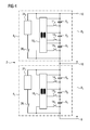
- FIG. 4 differs from the energy storage device 2 according to FIG. 3 in that in each case electrically parallel to the series connection of the n memory cells 6 1 to 6 n of each memory module 4 1 , 4 2 a series connection of a power resistor 24 1 or 24 2 and a module switch 26 1 and 26 2 is connected.
- the high voltage lines 20 and 22 are no longer available.
- each memory module 4 1 , 4 2 ,... of an energy storage arrangement 2 has a module heat sink 28 1 , 28 2 ,..., Which is needed to cool the memory cells 6 1 to 6 n .
- the power resistor 24 1 thermally conductively connected.
- the memory cells 6 1 to 6 n of this memory module 4 1 are connected.
- the generated heat loss is removed by means of the module heat sink 28 1 from the memory module 4 1 . This is illustrated by the heat flow 30.
- the module heat sink 28 1 is formed as an air cooling body.
- a module heat sink 28 1 but also a liquid heat sink or a cooling plate can be provided.
- Memory modules 4 1 to 4 m of an energy storage device 2 each one Cooling plate as a module heat sink 28 1 to 28 m , can be mounted together on a heat sink of a hybrid vehicle or a traction converter of a tram.
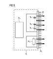
- each is a module control device 32 1 to 32 m in each memory module 4 1 to 4 m of the energy storage device 2 is provided.
- a module voltage U 1 , U 2 , ..., to n cell switch 14 1 to 14 n of a module 4 1 to 4 m and the module switch 26 1 , 26 2 , ..., 26 m actuated.
- the 2ellenbonden each represent a measure of the state of charge of a memory cell 6 1 to 6 n of a module 4 1 to 4 m .
- defective and older memory modules 4 1 to 4 m of an existing energy storage device 2 can be exchanged for new memory modules 4 1 to 4 m without much effort, since the memory modules 4 1 to 4 m of an energy storage device 2 are no longer interconnected with high voltage lines 20 and 22 ,
- accumulator cells in particular lithium-ion cells
- a traction drive for example a tram
- double-layer capacitors are preferred as memory cells 6 1 to 6 n .
- the advantage of the accumulators is that they can store and deliver large amounts of energy.
- the advantage of the double-layer capacitors is that they can absorb and deliver large electrical power.
- the energy storage device 2 due to a pending voltage of, for example, 820V from eight memory modules 4 1 to 4 8 , each having forty-eight memory cells 6 1 to 6 48 . Since no high-voltage lines 20, 22 for the interconnection of the individual memory modules 4 1 to 4 8 with the terminals 10 and 8 of the energy storage device 2 more are needed, an energy storage device 2 with memory modules according to the invention 4 1 to 4 m for a high voltage application very compact without much effort being constructed.
Landscapes
- Engineering & Computer Science (AREA)
- Power Engineering (AREA)
- Microelectronics & Electronic Packaging (AREA)
- Life Sciences & Earth Sciences (AREA)
- Sustainable Development (AREA)
- Sustainable Energy (AREA)
- Transportation (AREA)
- Mechanical Engineering (AREA)
- Charge And Discharge Circuits For Batteries Or The Like (AREA)
- Electric Propulsion And Braking For Vehicles (AREA)
Applications Claiming Priority (1)
| Application Number | Priority Date | Filing Date | Title |
|---|---|---|---|
| DE102010029427A DE102010029427A1 (de) | 2010-05-28 | 2010-05-28 | Energiespeicheranordnung |
Publications (3)
| Publication Number | Publication Date |
|---|---|
| EP2408086A2 true EP2408086A2 (fr) | 2012-01-18 |
| EP2408086A3 EP2408086A3 (fr) | 2015-04-08 |
| EP2408086B1 EP2408086B1 (fr) | 2016-11-16 |
Family
ID=44800905
Family Applications (1)
| Application Number | Title | Priority Date | Filing Date |
|---|---|---|---|
| EP11161438.4A Active EP2408086B1 (fr) | 2010-05-28 | 2011-04-07 | Agencement d'accumulation d'énergie |
Country Status (5)
| Country | Link |
|---|---|
| US (1) | US9053869B2 (fr) |
| EP (1) | EP2408086B1 (fr) |
| CN (1) | CN102263427B (fr) |
| DE (1) | DE102010029427A1 (fr) |
| ES (1) | ES2615171T3 (fr) |
Families Citing this family (17)
| Publication number | Priority date | Publication date | Assignee | Title |
|---|---|---|---|---|
| WO2012172468A2 (fr) * | 2011-06-11 | 2012-12-20 | Sendyne Corp. | Procédé de redistribution de charge destiné à des réseaux de cellules |
| US9564275B2 (en) | 2012-03-09 | 2017-02-07 | The Paper Battery Co. | Supercapacitor structures |
| DE102012015621A1 (de) | 2012-08-07 | 2014-02-13 | Winfried Schimmelpfennig | Kapazitives Energieübertragungsverfahren |
| US8901888B1 (en) | 2013-07-16 | 2014-12-02 | Christopher V. Beckman | Batteries for optimizing output and charge balance with adjustable, exportable and addressable characteristics |
| US9502910B2 (en) * | 2013-03-15 | 2016-11-22 | Samsung Electro-Mechanics Co., Ltd. | Power charging apparatus and battery apparatus |
| EP2973836A4 (fr) | 2013-03-15 | 2017-03-22 | The Paper Battery Company, Inc. | Structures de stockage d'énergie et leurs procédés de fabrication |
| US9583277B2 (en) | 2013-09-30 | 2017-02-28 | The Paper Battery Company, Inc. | Ultra-capacitor structures and electronic systems with ultra-capacitor structures |
| EP3026750A1 (fr) | 2014-11-28 | 2016-06-01 | Siemens Aktiengesellschaft | Procédé de mise en symétrie d'un système d'accumulation d'énergie |
| EP3029829A1 (fr) | 2014-12-05 | 2016-06-08 | Siemens Aktiengesellschaft | Procédé de transmission commune de signaux de commande et de signaux de données numériques |
| DE102015112524A1 (de) * | 2015-07-30 | 2017-02-02 | Halla Visteon Climate Control Corporation | Verfahren zur Spannungsbalancierung von in Reihe geschalteten Kondensatoren |
| WO2017054148A1 (fr) * | 2015-09-30 | 2017-04-06 | 长园科技实业股份有限公司 | Structure d'équilibrage d'éléments de batterie |
| EP3185660A1 (fr) | 2015-12-22 | 2017-06-28 | Siemens Aktiengesellschaft | Agencement de rails conducteurs |
| DE102017209674A1 (de) * | 2017-06-08 | 2018-12-13 | Robert Bosch Gmbh | Verfahren und Vorrichtung zum Betrieb eines elektrischen Energiespeichersystems sowie elektrisches Energiespeichersystem mit der Vorrichtung und entsprechende Verwendung |
| WO2019171662A1 (fr) * | 2018-03-08 | 2019-09-12 | 三洋電機株式会社 | Dispositif de gestion et système de stockage d'électricité |
| US20210408807A1 (en) * | 2020-06-30 | 2021-12-30 | Avx Corporation | System and Method for Balancing Ultracapacitors |
| CN112072731B (zh) * | 2020-08-25 | 2022-05-13 | 南通大学 | 一种用于电池主动均衡的双电容电路设计及其均衡方法 |
| EP4383513A1 (fr) * | 2022-12-05 | 2024-06-12 | Siemens Aktiengesellschaft | Système de tampon électrique comprenant des condensateurs à double couche |
Family Cites Families (25)
| Publication number | Priority date | Publication date | Assignee | Title |
|---|---|---|---|---|
| EP1047172A3 (fr) * | 1999-04-21 | 2001-05-23 | Nagano Japan Radio Co., Ltd. | Unité de transport d'énergie, unité de charge et unité d'alimentation |
| US6140800A (en) | 1999-05-27 | 2000-10-31 | Peterson; William Anders | Autonomous battery equalization circuit |
| FR2805934B1 (fr) * | 2000-03-01 | 2002-07-26 | Agence Spatiale Europeenne | Procede et dispositif d'equilibrage des charges d'une pluralite de cellules de batteries montees en serie |
| AU2001276641A1 (en) * | 2000-08-18 | 2002-02-25 | Vinzenz V. Harri | Current-accumulator module comprising batteries and capacitors, in particular, supercapacitors |
| US6642693B2 (en) * | 2000-11-21 | 2003-11-04 | Nagano Japan Radio Co., Ltd. | Voltage equalizing apparatus for battery devices |
| JP3630303B2 (ja) * | 2000-11-21 | 2005-03-16 | 長野日本無線株式会社 | 蓄電素子の電圧均等化装置 |
| JP4605952B2 (ja) * | 2001-08-29 | 2011-01-05 | 株式会社日立製作所 | 蓄電装置及びその制御方法 |
| US7157882B2 (en) * | 2002-11-22 | 2007-01-02 | Milwaukee Electric Tool Corporation | Method and system for battery protection employing a selectively-actuated switch |
| DE102004031216A1 (de) | 2004-06-28 | 2006-01-19 | Siemens Ag | Vorrichtung und Verfahren zum Ladungsausgleich in Reihe geschalteter Energiespeicher |
| US20060022646A1 (en) * | 2004-07-28 | 2006-02-02 | Moore Stephen W | Method for battery cold-temperature warm-up mechanism using cell equilization hardware |
| JP4186916B2 (ja) * | 2004-11-18 | 2008-11-26 | 株式会社デンソー | 組電池管理装置 |
| DE102005034588A1 (de) * | 2005-07-25 | 2007-02-01 | Temic Automotive Electric Motors Gmbh | Energiespeicher |
| JP4374351B2 (ja) * | 2006-04-12 | 2009-12-02 | 矢崎総業株式会社 | 充電状態調整装置 |
| WO2007148745A1 (fr) * | 2006-06-22 | 2007-12-27 | Fdk Corporation | Cellule d'accumulation multi-sÉrie, dispositif À cellule d'accumulation en sÉrie et circuit de correction de l'Équilibre de tension pour cellule en sÉrie |
| KR101124800B1 (ko) * | 2007-02-09 | 2012-03-23 | 한국과학기술원 | 전하 균일 장치 |
| US8288991B2 (en) * | 2007-04-18 | 2012-10-16 | Valeo Equipements Electriques Moteur | Energy storage device with assembly of energy storage cells and balancing circuit |
| US7804276B2 (en) | 2007-05-01 | 2010-09-28 | Infineon Technologies Ag | Circuit arrangement and method for transferring electrical charge between accumulators of an accumulator arrangement including a series circuit of accumulators |
| KR101107999B1 (ko) * | 2007-10-16 | 2012-01-25 | 한국과학기술원 | 전압 센서와 전하 균일 장치가 결합된 배터리 운용 시스템 |
| JP4499164B2 (ja) * | 2008-02-25 | 2010-07-07 | 岩崎電気株式会社 | 充電装置及び充電方法 |
| JP2010035392A (ja) * | 2008-07-31 | 2010-02-12 | Panasonic Corp | 不均衡低減回路、電源装置、及び不均衡低減方法 |
| US8350528B2 (en) * | 2009-02-04 | 2013-01-08 | Samsung Sdi Co., Ltd. | Battery pack and balancing method of battery cells |
| JP5133926B2 (ja) * | 2009-03-26 | 2013-01-30 | 株式会社日立製作所 | 車両用電池システム |
| CN102365804B (zh) * | 2009-03-31 | 2015-02-18 | 岩崎电气株式会社 | 充电装置 |
| US20100289453A1 (en) * | 2009-05-15 | 2010-11-18 | Ford Global Technologies, Llc | Vehicle power system |
| US8541980B2 (en) * | 2009-05-22 | 2013-09-24 | Intersil Americas LLC | System and method for cell balancing and charging |
-
2010
- 2010-05-28 DE DE102010029427A patent/DE102010029427A1/de not_active Withdrawn
-
2011
- 2011-04-07 EP EP11161438.4A patent/EP2408086B1/fr active Active
- 2011-04-07 ES ES11161438.4T patent/ES2615171T3/es active Active
- 2011-05-27 US US13/117,241 patent/US9053869B2/en active Active
- 2011-05-27 CN CN201110141378.XA patent/CN102263427B/zh not_active Expired - Fee Related
Also Published As
| Publication number | Publication date |
|---|---|
| ES2615171T3 (es) | 2017-06-05 |
| CN102263427B (zh) | 2014-02-19 |
| DE102010029427A1 (de) | 2011-12-01 |
| US20120139492A1 (en) | 2012-06-07 |
| CN102263427A (zh) | 2011-11-30 |
| EP2408086A3 (fr) | 2015-04-08 |
| US9053869B2 (en) | 2015-06-09 |
| EP2408086B1 (fr) | 2016-11-16 |
Similar Documents
| Publication | Publication Date | Title |
|---|---|---|
| EP2408086B1 (fr) | Agencement d'accumulation d'énergie | |
| EP2705564B1 (fr) | Procédé de commande d'une batterie et batterie pour la mise en oeuvre du procédé | |
| DE102008021090B4 (de) | Schaltungsanordnung und Verfahren zum Austausch elektrischer Ladung zwischen Akkumulatoren einer Akkumulatoranordnung | |
| EP2419751A1 (fr) | Détermination de la résistance interne d'un élément d'une batterie de traction en cas d'équilibrage inductif des éléments | |
| EP2168221B1 (fr) | Accumulateur | |
| WO2007147660A1 (fr) | Dispositif et procédé pour charger un accumulateur d'énergie | |
| DE102014212933B3 (de) | Vorrichtung und Verfahren zum Ladezustandsausgleich für ein Batteriesystem | |
| WO2017060354A1 (fr) | Dispositif de batterie de véhicule | |
| DE102010037094A1 (de) | Ladungsausgleichsschaltung und Verfahren zur vorausschauenden Steuerung des Ladungsausgleichs | |
| DE102014006772A1 (de) | Batteriesystem für ein Kraftfahrzeug mit zwei Spannungskreisen | |
| DE102018221234A1 (de) | Batterieeinheit | |
| EP1641650A1 (fr) | Limiteur de surtension concu pour un convertisseur de courant de traction | |
| DE102014006746A1 (de) | Batteriesystem | |
| DE102012009219A1 (de) | Batteriemodul, elektrisches Energiesystem in einem Kraftfahrzeug und Verfahren zum Betreiben eines Batteriemoduls | |
| DE102014221867A1 (de) | Verfahren und Schaltungsanordnung zum aktiven Cell-Balancing eines elektrischen Energiespeichers | |
| DE102016212557A1 (de) | Batteriesystem zum Versorgen eines Spannungsnetzes mit elektrischer Energie | |
| WO2013113585A2 (fr) | Procédé d'équilibrage de charge d'éléments de batterie, système de batterie et véhicule automobile équipé d'un tel système de batterie | |
| EP3173280A1 (fr) | Batterie, véhicule comprenant une telle batterie et utilisation d'une telle batterie | |
| DE102010001423A1 (de) | Batterie mit induktivem Cell-Balancing | |
| DE102011077664A1 (de) | Energiespeichersystem mit einer Vergleichmäßigungseinrichtung zum Vergleichmäßigen von Ladezuständen von Energiespeichereinheiten | |
| DE102018213897A1 (de) | Fehlertolerantes Bordnetzmodul mit zwei parallel geschalteten DC/DC-Wandlern | |
| DE102020004578A1 (de) | Spannungswandler und Verfahren zum Laden eines elektrischen Energiepeichers eines elektrisch betriebenen Fahrzeugs | |
| WO2011042331A2 (fr) | Système accumulateur et procédé d'équilibrage des piles d'un système accumulateur | |
| DE102014215733A1 (de) | Batteriesystem mit einer zum Versorgen eines Hochvoltnetzes mit elektrischer Energie ausgebildeten Batterie, die elektrische Energie zum Versorgen eines Niedervoltnetz bereitstellt und entsprechendes Verfahren | |
| DE102018116480A1 (de) | Batterieschaltung mit Multiplexer-Batteriemodulen |
Legal Events
| Date | Code | Title | Description |
|---|---|---|---|
| AK | Designated contracting states |
Kind code of ref document: A2 Designated state(s): AL AT BE BG CH CY CZ DE DK EE ES FI FR GB GR HR HU IE IS IT LI LT LU LV MC MK MT NL NO PL PT RO RS SE SI SK SM TR |
|
| AX | Request for extension of the european patent |
Extension state: BA ME |
|
| PUAI | Public reference made under article 153(3) epc to a published international application that has entered the european phase |
Free format text: ORIGINAL CODE: 0009012 |
|
| RAP1 | Party data changed (applicant data changed or rights of an application transferred) |
Owner name: SIEMENS AKTIENGESELLSCHAFT |
|
| PUAL | Search report despatched |
Free format text: ORIGINAL CODE: 0009013 |
|
| AK | Designated contracting states |
Kind code of ref document: A3 Designated state(s): AL AT BE BG CH CY CZ DE DK EE ES FI FR GB GR HR HU IE IS IT LI LT LU LV MC MK MT NL NO PL PT RO RS SE SI SK SM TR |
|
| AX | Request for extension of the european patent |
Extension state: BA ME |
|
| RIC1 | Information provided on ipc code assigned before grant |
Ipc: H01G 9/155 00000000ALI20150304BHEP Ipc: B60L 11/18 20060101ALI20150304BHEP Ipc: H02J 7/00 20060101AFI20150304BHEP |
|
| 17P | Request for examination filed |
Effective date: 20151008 |
|
| RBV | Designated contracting states (corrected) |
Designated state(s): AL AT BE BG CH CY CZ DE DK EE ES FI FR GB GR HR HU IE IS IT LI LT LU LV MC MK MT NL NO PL PT RO RS SE SI SK SM TR |
|
| RIC1 | Information provided on ipc code assigned before grant |
Ipc: H02J 7/00 20060101AFI20160504BHEP Ipc: B60L 11/18 20060101ALI20160504BHEP Ipc: H01G 9/00 20060101ALI20160504BHEP |
|
| GRAP | Despatch of communication of intention to grant a patent |
Free format text: ORIGINAL CODE: EPIDOSNIGR1 |
|
| INTG | Intention to grant announced |
Effective date: 20160617 |
|
| GRAS | Grant fee paid |
Free format text: ORIGINAL CODE: EPIDOSNIGR3 |
|
| GRAA | (expected) grant |
Free format text: ORIGINAL CODE: 0009210 |
|
| AK | Designated contracting states |
Kind code of ref document: B1 Designated state(s): AL AT BE BG CH CY CZ DE DK EE ES FI FR GB GR HR HU IE IS IT LI LT LU LV MC MK MT NL NO PL PT RO RS SE SI SK SM TR |
|
| REG | Reference to a national code |
Ref country code: GB Ref legal event code: FG4D Free format text: NOT ENGLISH |
|
| REG | Reference to a national code |
Ref country code: CH Ref legal event code: EP |
|
| REG | Reference to a national code |
Ref country code: IE Ref legal event code: FG4D Free format text: LANGUAGE OF EP DOCUMENT: GERMAN |
|
| REG | Reference to a national code |
Ref country code: AT Ref legal event code: REF Ref document number: 846741 Country of ref document: AT Kind code of ref document: T Effective date: 20161215 |
|
| REG | Reference to a national code |
Ref country code: DE Ref legal event code: R096 Ref document number: 502011011136 Country of ref document: DE |
|
| REG | Reference to a national code |
Ref country code: NL Ref legal event code: FP |
|
| PG25 | Lapsed in a contracting state [announced via postgrant information from national office to epo] |
Ref country code: LV Free format text: LAPSE BECAUSE OF FAILURE TO SUBMIT A TRANSLATION OF THE DESCRIPTION OR TO PAY THE FEE WITHIN THE PRESCRIBED TIME-LIMIT Effective date: 20161116 |
|
| REG | Reference to a national code |
Ref country code: SE Ref legal event code: TRGR |
|
| REG | Reference to a national code |
Ref country code: LT Ref legal event code: MG4D |
|
| REG | Reference to a national code |
Ref country code: FR Ref legal event code: PLFP Year of fee payment: 7 |
|
| PG25 | Lapsed in a contracting state [announced via postgrant information from national office to epo] |
Ref country code: LT Free format text: LAPSE BECAUSE OF FAILURE TO SUBMIT A TRANSLATION OF THE DESCRIPTION OR TO PAY THE FEE WITHIN THE PRESCRIBED TIME-LIMIT Effective date: 20161116 Ref country code: GR Free format text: LAPSE BECAUSE OF FAILURE TO SUBMIT A TRANSLATION OF THE DESCRIPTION OR TO PAY THE FEE WITHIN THE PRESCRIBED TIME-LIMIT Effective date: 20170217 Ref country code: NO Free format text: LAPSE BECAUSE OF FAILURE TO SUBMIT A TRANSLATION OF THE DESCRIPTION OR TO PAY THE FEE WITHIN THE PRESCRIBED TIME-LIMIT Effective date: 20170216 |
|
| PG25 | Lapsed in a contracting state [announced via postgrant information from national office to epo] |
Ref country code: FI Free format text: LAPSE BECAUSE OF FAILURE TO SUBMIT A TRANSLATION OF THE DESCRIPTION OR TO PAY THE FEE WITHIN THE PRESCRIBED TIME-LIMIT Effective date: 20161116 Ref country code: HR Free format text: LAPSE BECAUSE OF FAILURE TO SUBMIT A TRANSLATION OF THE DESCRIPTION OR TO PAY THE FEE WITHIN THE PRESCRIBED TIME-LIMIT Effective date: 20161116 Ref country code: PT Free format text: LAPSE BECAUSE OF FAILURE TO SUBMIT A TRANSLATION OF THE DESCRIPTION OR TO PAY THE FEE WITHIN THE PRESCRIBED TIME-LIMIT Effective date: 20170316 Ref country code: RS Free format text: LAPSE BECAUSE OF FAILURE TO SUBMIT A TRANSLATION OF THE DESCRIPTION OR TO PAY THE FEE WITHIN THE PRESCRIBED TIME-LIMIT Effective date: 20161116 Ref country code: PL Free format text: LAPSE BECAUSE OF FAILURE TO SUBMIT A TRANSLATION OF THE DESCRIPTION OR TO PAY THE FEE WITHIN THE PRESCRIBED TIME-LIMIT Effective date: 20161116 |
|
| REG | Reference to a national code |
Ref country code: ES Ref legal event code: FG2A Ref document number: 2615171 Country of ref document: ES Kind code of ref document: T3 Effective date: 20170605 |
|
| PG25 | Lapsed in a contracting state [announced via postgrant information from national office to epo] |
Ref country code: SK Free format text: LAPSE BECAUSE OF FAILURE TO SUBMIT A TRANSLATION OF THE DESCRIPTION OR TO PAY THE FEE WITHIN THE PRESCRIBED TIME-LIMIT Effective date: 20161116 Ref country code: CZ Free format text: LAPSE BECAUSE OF FAILURE TO SUBMIT A TRANSLATION OF THE DESCRIPTION OR TO PAY THE FEE WITHIN THE PRESCRIBED TIME-LIMIT Effective date: 20161116 Ref country code: EE Free format text: LAPSE BECAUSE OF FAILURE TO SUBMIT A TRANSLATION OF THE DESCRIPTION OR TO PAY THE FEE WITHIN THE PRESCRIBED TIME-LIMIT Effective date: 20161116 Ref country code: RO Free format text: LAPSE BECAUSE OF FAILURE TO SUBMIT A TRANSLATION OF THE DESCRIPTION OR TO PAY THE FEE WITHIN THE PRESCRIBED TIME-LIMIT Effective date: 20161116 Ref country code: DK Free format text: LAPSE BECAUSE OF FAILURE TO SUBMIT A TRANSLATION OF THE DESCRIPTION OR TO PAY THE FEE WITHIN THE PRESCRIBED TIME-LIMIT Effective date: 20161116 |
|
| REG | Reference to a national code |
Ref country code: DE Ref legal event code: R097 Ref document number: 502011011136 Country of ref document: DE |
|
| RAP2 | Party data changed (patent owner data changed or rights of a patent transferred) |
Owner name: SIEMENS AKTIENGESELLSCHAFT |
|
| PG25 | Lapsed in a contracting state [announced via postgrant information from national office to epo] |
Ref country code: SM Free format text: LAPSE BECAUSE OF FAILURE TO SUBMIT A TRANSLATION OF THE DESCRIPTION OR TO PAY THE FEE WITHIN THE PRESCRIBED TIME-LIMIT Effective date: 20161116 Ref country code: BG Free format text: LAPSE BECAUSE OF FAILURE TO SUBMIT A TRANSLATION OF THE DESCRIPTION OR TO PAY THE FEE WITHIN THE PRESCRIBED TIME-LIMIT Effective date: 20170216 |
|
| PLBE | No opposition filed within time limit |
Free format text: ORIGINAL CODE: 0009261 |
|
| STAA | Information on the status of an ep patent application or granted ep patent |
Free format text: STATUS: NO OPPOSITION FILED WITHIN TIME LIMIT |
|
| REG | Reference to a national code |
Ref country code: CH Ref legal event code: NV Representative=s name: SIEMENS SCHWEIZ AG, CH Ref country code: CH Ref legal event code: PCOW Free format text: NEW ADDRESS: WERNER-VON-SIEMENS-STRASSE 1, 80333 MUENCHEN (DE) |
|
| 26N | No opposition filed |
Effective date: 20170817 |
|
| PG25 | Lapsed in a contracting state [announced via postgrant information from national office to epo] |
Ref country code: SI Free format text: LAPSE BECAUSE OF FAILURE TO SUBMIT A TRANSLATION OF THE DESCRIPTION OR TO PAY THE FEE WITHIN THE PRESCRIBED TIME-LIMIT Effective date: 20161116 |
|
| REG | Reference to a national code |
Ref country code: CH Ref legal event code: PL |
|
| REG | Reference to a national code |
Ref country code: IE Ref legal event code: MM4A |
|
| PG25 | Lapsed in a contracting state [announced via postgrant information from national office to epo] |
Ref country code: MC Free format text: LAPSE BECAUSE OF FAILURE TO SUBMIT A TRANSLATION OF THE DESCRIPTION OR TO PAY THE FEE WITHIN THE PRESCRIBED TIME-LIMIT Effective date: 20161116 |
|
| PG25 | Lapsed in a contracting state [announced via postgrant information from national office to epo] |
Ref country code: LU Free format text: LAPSE BECAUSE OF NON-PAYMENT OF DUE FEES Effective date: 20170407 Ref country code: LI Free format text: LAPSE BECAUSE OF NON-PAYMENT OF DUE FEES Effective date: 20170430 Ref country code: CH Free format text: LAPSE BECAUSE OF NON-PAYMENT OF DUE FEES Effective date: 20170430 |
|
| REG | Reference to a national code |
Ref country code: FR Ref legal event code: PLFP Year of fee payment: 8 |
|
| PG25 | Lapsed in a contracting state [announced via postgrant information from national office to epo] |
Ref country code: IE Free format text: LAPSE BECAUSE OF NON-PAYMENT OF DUE FEES Effective date: 20170407 |
|
| REG | Reference to a national code |
Ref country code: AT Ref legal event code: MM01 Ref document number: 846741 Country of ref document: AT Kind code of ref document: T Effective date: 20170407 |
|
| PG25 | Lapsed in a contracting state [announced via postgrant information from national office to epo] |
Ref country code: AT Free format text: LAPSE BECAUSE OF NON-PAYMENT OF DUE FEES Effective date: 20170407 |
|
| PG25 | Lapsed in a contracting state [announced via postgrant information from national office to epo] |
Ref country code: MT Free format text: LAPSE BECAUSE OF FAILURE TO SUBMIT A TRANSLATION OF THE DESCRIPTION OR TO PAY THE FEE WITHIN THE PRESCRIBED TIME-LIMIT Effective date: 20161116 |
|
| PG25 | Lapsed in a contracting state [announced via postgrant information from national office to epo] |
Ref country code: HU Free format text: LAPSE BECAUSE OF FAILURE TO SUBMIT A TRANSLATION OF THE DESCRIPTION OR TO PAY THE FEE WITHIN THE PRESCRIBED TIME-LIMIT; INVALID AB INITIO Effective date: 20110407 |
|
| PGFP | Annual fee paid to national office [announced via postgrant information from national office to epo] |
Ref country code: SE Payment date: 20190411 Year of fee payment: 9 |
|
| PG25 | Lapsed in a contracting state [announced via postgrant information from national office to epo] |
Ref country code: CY Free format text: LAPSE BECAUSE OF NON-PAYMENT OF DUE FEES Effective date: 20161116 |
|
| PG25 | Lapsed in a contracting state [announced via postgrant information from national office to epo] |
Ref country code: MK Free format text: LAPSE BECAUSE OF FAILURE TO SUBMIT A TRANSLATION OF THE DESCRIPTION OR TO PAY THE FEE WITHIN THE PRESCRIBED TIME-LIMIT Effective date: 20161116 |
|
| PG25 | Lapsed in a contracting state [announced via postgrant information from national office to epo] |
Ref country code: TR Free format text: LAPSE BECAUSE OF FAILURE TO SUBMIT A TRANSLATION OF THE DESCRIPTION OR TO PAY THE FEE WITHIN THE PRESCRIBED TIME-LIMIT Effective date: 20161116 |
|
| PG25 | Lapsed in a contracting state [announced via postgrant information from national office to epo] |
Ref country code: AL Free format text: LAPSE BECAUSE OF FAILURE TO SUBMIT A TRANSLATION OF THE DESCRIPTION OR TO PAY THE FEE WITHIN THE PRESCRIBED TIME-LIMIT Effective date: 20161116 Ref country code: IS Free format text: LAPSE BECAUSE OF FAILURE TO SUBMIT A TRANSLATION OF THE DESCRIPTION OR TO PAY THE FEE WITHIN THE PRESCRIBED TIME-LIMIT Effective date: 20170316 |
|
| PG25 | Lapsed in a contracting state [announced via postgrant information from national office to epo] |
Ref country code: SE Free format text: LAPSE BECAUSE OF NON-PAYMENT OF DUE FEES Effective date: 20200408 |
|
| REG | Reference to a national code |
Ref country code: GB Ref legal event code: 732E Free format text: REGISTERED BETWEEN 20230112 AND 20230118 |
|
| REG | Reference to a national code |
Ref country code: DE Ref legal event code: R081 Ref document number: 502011011136 Country of ref document: DE Owner name: MERITOR ELECTRIC VEHICLES GERMANY GMBH, DE Free format text: FORMER OWNER: SIEMENS AKTIENGESELLSCHAFT, 80333 MUENCHEN, DE |
|
| P01 | Opt-out of the competence of the unified patent court (upc) registered |
Effective date: 20230531 |
|
| PGFP | Annual fee paid to national office [announced via postgrant information from national office to epo] |
Ref country code: NL Payment date: 20240426 Year of fee payment: 14 |
|
| PGFP | Annual fee paid to national office [announced via postgrant information from national office to epo] |
Ref country code: ES Payment date: 20240503 Year of fee payment: 14 |
|
| PGFP | Annual fee paid to national office [announced via postgrant information from national office to epo] |
Ref country code: BE Payment date: 20240429 Year of fee payment: 14 |
|
| PGFP | Annual fee paid to national office [announced via postgrant information from national office to epo] |
Ref country code: DE Payment date: 20250429 Year of fee payment: 15 |
|
| PGFP | Annual fee paid to national office [announced via postgrant information from national office to epo] |
Ref country code: GB Payment date: 20250428 Year of fee payment: 15 |
|
| PGFP | Annual fee paid to national office [announced via postgrant information from national office to epo] |
Ref country code: IT Payment date: 20250422 Year of fee payment: 15 |
|
| PGFP | Annual fee paid to national office [announced via postgrant information from national office to epo] |
Ref country code: FR Payment date: 20250425 Year of fee payment: 15 |
|
| REG | Reference to a national code |
Ref country code: NL Ref legal event code: MM Effective date: 20250501 |
|
| REG | Reference to a national code |
Ref country code: BE Ref legal event code: MM Effective date: 20250430 |
|
| PG25 | Lapsed in a contracting state [announced via postgrant information from national office to epo] |
Ref country code: NL Free format text: LAPSE BECAUSE OF NON-PAYMENT OF DUE FEES Effective date: 20250501 |
|
| PG25 | Lapsed in a contracting state [announced via postgrant information from national office to epo] |
Ref country code: BE Free format text: LAPSE BECAUSE OF NON-PAYMENT OF DUE FEES Effective date: 20250430 |