EP2408649B1 - Profilé de retenue et pièce composite pour l'habillage d'un intérieur de véhicule automobile - Google Patents
Profilé de retenue et pièce composite pour l'habillage d'un intérieur de véhicule automobile Download PDFInfo
- Publication number
- EP2408649B1 EP2408649B1 EP10710248.5A EP10710248A EP2408649B1 EP 2408649 B1 EP2408649 B1 EP 2408649B1 EP 10710248 A EP10710248 A EP 10710248A EP 2408649 B1 EP2408649 B1 EP 2408649B1
- Authority
- EP
- European Patent Office
- Prior art keywords
- skin
- seam
- holding profile
- groove
- wings
- Prior art date
- Legal status (The legal status is an assumption and is not a legal conclusion. Google has not performed a legal analysis and makes no representation as to the accuracy of the status listed.)
- Active
Links
Images



Classifications
-
- B—PERFORMING OPERATIONS; TRANSPORTING
- B60—VEHICLES IN GENERAL
- B60R—VEHICLES, VEHICLE FITTINGS, OR VEHICLE PARTS, NOT OTHERWISE PROVIDED FOR
- B60R13/00—Elements for body-finishing, identifying, or decorating; Arrangements or adaptations for advertising purposes
- B60R13/02—Internal Trim mouldings ; Internal Ledges; Wall liners for passenger compartments; Roof liners
-
- B—PERFORMING OPERATIONS; TRANSPORTING
- B60—VEHICLES IN GENERAL
- B60R—VEHICLES, VEHICLE FITTINGS, OR VEHICLE PARTS, NOT OTHERWISE PROVIDED FOR
- B60R13/00—Elements for body-finishing, identifying, or decorating; Arrangements or adaptations for advertising purposes
- B60R13/02—Internal Trim mouldings ; Internal Ledges; Wall liners for passenger compartments; Roof liners
- B60R2013/0281—Internal Trim mouldings ; Internal Ledges; Wall liners for passenger compartments; Roof liners made of a plurality of visible parts
-
- B—PERFORMING OPERATIONS; TRANSPORTING
- B60—VEHICLES IN GENERAL
- B60R—VEHICLES, VEHICLE FITTINGS, OR VEHICLE PARTS, NOT OTHERWISE PROVIDED FOR
- B60R13/00—Elements for body-finishing, identifying, or decorating; Arrangements or adaptations for advertising purposes
- B60R13/02—Internal Trim mouldings ; Internal Ledges; Wall liners for passenger compartments; Roof liners
- B60R2013/0293—Connection or positioning of adjacent panels
Definitions
- the invention relates to a method for producing a composite part and a composite part having a first skin, a second skin and a holding profile connected to the first and second skin by means of a respective seam and a holding profile for such a method or composite part.
- the coating presented there has a first and a second skin, which are interconnected by means of a functional seam.
- the interconnected First and second skins are additionally sewn by means of decorative stitching with a retaining profile, wherein the retaining profile has a pin arranged on the underside of the retaining profile.
- the consisting of the hides and the retaining profile composite part is connected to a carrier, wherein the pin of the holding profile engages in a recess of the carrier.
- alignment of the position of the first and second seam or the functional seam on the holding profile seaming swords are necessary, which must be milled at great expense according to CAD data.
- the correct positioning of the first and second skin prior to the introduction of the decorative seams and before the material connection with the retaining profile designed difficult.
- the composite part disclosed therein has at least a first and a second skin connected to the first, which are each connected to a holding profile.
- the retaining profile has substantially perpendicular to the seam extending tooth-like profiles, which engage behind the first and the second skin with the retaining profile of this and can be omitted a previous cohesive bonding between the first and second skin and the retaining profile. This has the advantage that the seams can be separated again in case of incorrect positions.
- An integral connection between the retaining profile and the first or second skin is made only after the sewing of the first and second skin with the holding profile.
- the composite part comprises a first and a second skin, which are arranged in a groove of a holding profile.
- a seam is introduced, which also serves as a functional and decorative stitching of the composite part.
- the retaining profile must protrude clearly from the carrier, so that the problem of producing a flat seam can not be solved satisfactorily.
- the precise adjustment of the seam course is difficult here as well, since the holding profile protrudes from the carrier.
- the object of the present invention is to improve a method for producing a composite part and a composite part, a holding profile and a sewing device used in the method, so that the disadvantages listed are avoided.
- the invention is achieved by means of a holding profile with the features of claim 1, a method having the features of claim 4 and a composite part having the features of claim 12.
- the composite part according to the invention has a holding profile according to the invention with a groove extending in a first direction, wherein in each case an end section of a first and an end section of a second skin are arranged in the groove.
- the end portion of the first skin and the end portion of the second skin are first inserted into this groove extending in a first direction of the retaining profile.
- the first direction is determined by the course of the seam, i. if the holding profile is curved, the first direction is also "curved".
- the groove By means of the groove, the end portions of the first and second skin can be held and / or guided, whereby the actual positioning of the first and second skin on the holding profile itself is greatly simplified.
- the groove preferably extends over the entire length of the holding profile in the first direction.
- the first and second skin may be connected to a first functional seam, wherein the functional seam is connected only to the first and second skin.
- the holding profile which is formed with one, preferably two, extending from the open end of the groove and the side walls in a second, to the first direction of Nutverlaufs substantially perpendicular, extending direction wings, with the connected skins, for example, on a Carrier can be arranged, wherein the holding profile is positively or materially connected to the carrier.
- the skins can be laminated on the carrier without any decorative or decorative seams applied.
- the course of the seam is predetermined by the functional seam, the retaining profile and a recess corresponding to the retaining profile. It is preferred if the holding profile is flexible or bendable and thus adapts to the profile of the recess of the carrier.
- the at least one wing of the retaining profile serves for the connection between a subsection of the first and second skin adjoining the end section and a first or second of the at least one wing of the retaining profile by means of a first or second seam.
- the first and second seams comprise at least one yarn. This means in particular that the connection between the end portion of the first and second skin and the first and second wings is such that at least one yarn at least partially engages behind the first and second wings from a visible side of the first and second skin ,
- the first and second seams are preferably decorative or decorative seams.
- first and second skin Since the end portions of the first and second skin are respectively held in the groove, only one layer of the first and second skin needs to be sutured to the first and second wings, respectively. This reduces the amount of material to be used of the first and second skin. Furthermore, the force to be applied for introducing the seam is reduced since only one layer of the first or second skin has to be pierced.
- first and second skin may be slightly pinched or loosely held in the groove. This makes it possible to influence the shape or the appearance of the visible from the visible side of the first and second skin joint between the first and second skin.
- the wings allow accurate positioning of the retaining profile in a recess of a carrier and serve as a distance or position holder. By means of the wings, an exact dimension of the depth and width of the recess is no longer necessary, since the wings are supported on a respective side wall of the groove mounted and opposing flange on the next to the recess and this limiting surface of the support.
- the wings have a material thickness which is smaller than the depth of the groove and in the range of less than 1.5 mm, preferably less than 1 mm, the slight elevation of the holding profile falls from the surface of the carrier, which is caused by the wing, not noticeably in the weight.
- the wing or wings are as a survey, especially when a first and a second skin are arranged in the retaining profile and the wing overlap the visible side, not substantially recognizable.
- a substantially planar conclusion between a visible side surface and the support arranged in a recess of the support profile without complicated adjustment is effected.
- first functional seam engages in addition to a first introduced into the wing seam first functional seam at least one side wall of the groove of the retaining profile.
- the composite part has a second functional seam connecting the first and second skin, which is arranged above the first functional seam from a visible side of the later composite part arranged on a carrier.
- the second functional seam viewed from the visible side, is closer than the first functional seam.
- the second functional seam is visibly arranged for the viewer and is perceived by a viewer as the actual functional seam connecting the first and second skin, since the first functional seam lying below this second functional seam is covered by the second functional seam.
- the first and the second functional seam can be introduced substantially simultaneously or within a single operation, which reduces the workload.
- first and the second skin are connected to one another by means of a functional seam arranged between the partial section and the end section, wherein the connection is preferably made prior to the insertion of the end sections into the groove.
- the functional seam can be arranged lying in the groove such that the functional seam is at least partially visible as a connection between the first and second skin from the visible side of the first and second skin forth.
- the functional suture described in the previous section is different from the first and second sutures described in the previous section, since they are introduced independently of them, before the first and second skin are guided into the groove.
- the end portions of the first and second skin have a length of 0.5 mm to 3 mm.
- the groove has a depth between 1 mm and 4 mm, preferably between 1.2 mm and 2.5 mm, and can accommodate the end portions and the functional seam without the end portions touching the bottom of the groove. As a result, bulges of the first and second skin in the region of the groove are avoided.
- the end portions may also be inserted into the groove such that one or both end portions rest on the bottom of the groove.
- the wing thickness or wall thickness of the wings is between 0.05 mm and 1 mm, preferably between 0.2 mm and 0.6 mm and particularly preferably between 0.35 mm and 0.5 mm.
- the wall thickness is in this case measured in the same direction as the depth of the groove, i. a substantially perpendicular to the first direction and from the second direction different, preferably substantially perpendicular to the second direction, third direction measured.
- the wall thickness is preferably selected such that the maximum holding force of a seam connecting the wing and a skin is greater than that for demolition of a wing in the third direction tearing force.
- This has advantages when trying to pull out a retaining profile from a recess of a wearer (eg in subsequently recognized quality defects), since too much stress tears the much cheaper retaining profile before the decorative stitching and the skin is not damaged.
- a breaking force of 15N is selected as the maximum breaking force, ie a pull of more than 15 N on a wing tears it off the retaining profile.
- the width of a wing along the second direction measured from the inside of the side wall of the groove to the outer edge of the wing towards between 2mm and 7mm, preferably between 2.5mm and 5mm.
- the wall thickness of a groove bounding the sidewall along the second direction is between 0.2mm and 2mm, with the width of the wing chosen to be flanged to the sidewall, i. the wing is wider than the width of the side wall. And so can serve as a flange.
- the width of the groove along the second direction is measured between the groove bounding inner sides of the side walls between 1mm and 4mm, preferably between 1.5mm and 3mm.
- the bottom of the groove delimiting bottom has a thickness in the range between 0.1 mm and 2mm. A measured from the outside of the side walls width of the groove is thus between 1.4mm and 8mm.
- the retaining profile is guided and / or held in a throat plate of a sewing device.
- the throat plate has a channel extending in the first direction Guide the holding profile on.
- the sewing apparatus also has two needles, with the channel for guiding the holding profile extending between the two needles.
- the first needle introduces the first functional seam
- the second needle introduces the second functional seam.
- only the first functional seam engages behind the side walls of the groove.
- the second functional seam only engages behind the first and second skin.
- the second needle is guided for this purpose at a small distance of preferably less than 2 mm along the open side of the groove.
- the process speed for producing a composite part of a first and second skin which are significantly increased with a holding profile via at least one first functional seam arranged in the groove, wherein the predetermined tolerance values can be maintained as described above.
- a second functional seam can be introduced by means of a second needle in a timely or simultaneous manner.
- the end sections of the first and second skin are guided by means of a center guide into the groove of the retaining profile and / or held in the groove of the retaining profile.
- a center guide in particular a seam center guide used in the presence of a functional seam, between the first and second skin is particularly suitable with regard to the mechanical production of the first and second seams.
- the center guide is adjusted so that the first and second skin are held securely in the groove, so that a subsequent introduction of the first and second seam with a required tolerance value of ⁇ 1 mm, preferably ⁇ 0.5 mm.
- the center guide presses the first and second skin or their end portions into the groove from the open side of the groove.
- the holding profile is guided and / or held in a throat plate of a sewing device.
- the throat plate has a channel extending in the first direction for guiding the holding profile.
- the sewing apparatus also has two needles, with the channel for guiding the holding profile extending between the two needles.
- the optional center guide is arranged centrally between the two needles in the channel for guiding the holding profile, so that an optional center guide can also engage centrally in the groove of the holding profile.
- the process speed for producing a composite part of a first and second skin, which are connected to a holding profile by means of a first and second seam can be significantly increased, wherein the predetermined tolerance values can be maintained as described above.
- the first and second skin connected to the retaining profile projects beyond the retaining profile in the first direction.
- the holding profile is shorter than the connecting line formed between the first and second skin, wherein the connecting line is preferably given by a functional seam.
- the connecting line is preferably given by a functional seam.
- the latter is inserted into a recess of a carrier such that the first and second decorative seams are visible from the visible side and the retaining profile is positively and / or materially bonded to the carrier is connected.
- a carrier such that the first and second decorative seams are visible from the visible side and the retaining profile is positively and / or materially bonded to the carrier is connected.
- it is also possible en the holding profile in a corresponding recess of the carrier.
- the retaining profile preferably has a pin on a underside facing the carrier, wherein the pin engages in the recess of the carrier and preferably has at least one armature for improved retention of the retaining profile.
- an improved positive clamping action of the pin can be achieved in the recess of the wearer.
- the recess of the carrier it is possible for the recess of the carrier to be stepped, ie for a first step to pick up the actual holding profile and the second step further projecting into the carrier receives the pin.
- Any stud, as measured along the third direction described in the previous section, measured from the bottom of the bottom of the groove has a length between 2mm and 6mm.
- Anchors arranged on the pin have a width measured in the second direction, which is preferably chosen such that an anchor arm of the anchor projects beyond the outside of the side wall of the groove between 0.1 mm and 1 mm.
- the at least two wings of the holding profile have a multiplicity of teeth and / or slots.
- rhombic cut-outs can be introduced into the wing.
- the teeth or the slots or rhombic sections of the wings extend transversely to the first direction of the groove. Due to the slots or the teeth, it is possible to curve the holding profile according to easily, with radii of curvature up to 30 mm are possible. As a result, a complicated seam course, which has curvatures, can be created in a simple manner. The geometry of the seam course is predetermined by the cut of the first and second skin.
- the holding profile consists of a preferably extruded plastic and has a Shore hardness between 25 and 100, preferably between 40 and 70.
- a holding profile made of a corresponding plastic has the necessary softness to create complicated curved seam courses.
- a Shore A hardness of the holding profile of> 50 if the first and / or second skin have a Shore A hardness of ⁇ 50 to meet the safety requirements for the prevention of head injuries.
- the measurement of the Shore A hardness can be carried out by means of a dynamic test according to the standard European "Commision for Europe (ECE) R21 Annex 4".
- the wings of the holding profile can be realized via textile, fleece or knitted fabric flags, in contrast to a holding profile produced in one piece by means of extrusion.
- the wings are glued or welded, for example.
- first and / or second skin materials such as leather, synthetic leather, plastics such.
- Suitable carriers are carriers with a spacer knitted fabric, front-foamed carriers or hard-laminated carriers made of plastics or knitted fabrics, wherein the carrier may have a retaining profile-receiving rail.
- a particularly advantageous embodiment provides that the holding profile and / or parts of the end portions are shortened at a defined distance from the course of the first functional seam.
- This shortening can be done parallel to the introduction of functional seams or also below.
- a component having two superposed end portions which are housed in a groove of a holding part, passed through a sewing machine.
- This sewing machine is designed so that it has a needle plate with a feed dog for further transport of the component during sewing.
- a transport wheel may be provided.
- At least one needle is provided, which connects the holding part with the two end portions. Parallel to this seam then a cutting blade is guided (see also Fig. 1a ), so that in a defined distance to the functional seam is given a straight conclusion. In this way, on the one hand, a smooth finish is achieved, and it is ensured that in any case the end sections and the retaining section are connected to one another, so that detachment can not occur here.
- the distance from the cutting edge can be very small in this case (for example in the range between 0.8 and 5 mm, preferably between 0.9 and 3 mm, particularly preferably between 1 and 2 mm).
- a corresponding sewing machine would therefore contain: at least one needle for introducing a respective seam and a throat plate for guiding a composite part to be created, wherein the sewing device has a needle for connecting a holding part on the one hand with two ends of a decorative part on the other.
- a wheel can be given, which is on the upper of the two end portions rolls, alternatively a transporter (this is preferred in embodiments in which the holding elements and / or the end sections still have "wings").
- This embodiment of the composite part has advantages in that the end of the retainer (retaining profile) is trimmed during the sewing process or subsequently in order to achieve an exact overall height. This results in a dimensionally accurate and also straight and aligned positioning in a corresponding carrier. As a result, on the one hand, the external appearance of a later composite part is very attractive. In particular, however, the overall height is limited or it does not necessarily increase in the seam, so that space can be saved accordingly.
- a second seam can still be provided, on the side facing away from the trim.
- This seam connects only two end portions just above or in alignment with an upper edge of the holding means.
- This seam has the task to make a functional seam visible and to preserve the visual impression of the functional seam. It would also be sufficient merely to provide only the seam closer to the trimming, but then the optical seam pattern would no longer be visible.
- radii of curvature in the range between about 40mm and 60mm are sought, as this has a particularly successful feel.
- Concave and convex areas are also possible, the retaining profile is universally applicable for composite parts, which are push-soft (spacer fabric), front foamed carriers or hard-laminated carriers.
- the composite of profile (piping) / decorative material is limited to a permanently defined length in the area of the seam. In this case, attaching a dipper / wave structure to the sides of the profile / piping adjacent to the groove can also be provided.
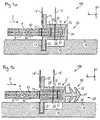
- the Fig. 1a shows a not belonging to the invention composite part 50, which is produced by means of a sewing device 100.
- the composite part 50 comprises a first skin 3, a first skin 4 and a retaining profile 2.
- the retaining profile has a groove 20 which is delimited by side walls 29 and a bottom 24 shown as a bottom. The groove extends in a first direction, which is given here by the y-direction.
- the wing thickness, the depth of the groove and the bottom thickness are measured here along the third direction z.
- the wing width, the width of the side wall and the width of the groove are measured along the second direction x.
- the first skin 3 and the second skin 4 are connected to each other before insertion of the end portions 31, 41 into the groove 20 by means of a functional seam 7.
- the functional seam 7 is introduced by the stitching of a yarn and defines the right side of the functional seam 7 lying end portions 31, 41 and the left
- the functional seam 7 helps to insert the first and second skin and is optional to the first functional seam 70 and to the second functional seam 71.
- the retaining profile 2 also has two adjoining the side walls 29 and each having a first wing 21 and a second wing 22 opposite the first wing 21, which adjoin the open end of the groove.
- the retaining profile is guided and held by means of a throat plate 16 with the skins 3, 4 introduced in the groove.
- the sewing device 100 has a feed dog 18 arranged on the throat plate 16.
- the throat plate 16 has a channel 17 for guiding a wing of the holding profile.
- the first wing 21 is guided in the channel 17.
- the guided by the conveyor 18 holding profile is guided in the region of a first needle 13 'and a second needle 14' of the sewing device 100, wherein the first needle 13 'for introducing the first functional seam 70 and the second needle 14' for introducing the second functional seam 71 is formed.
- the retaining profile 2 has the wings 21, 22, it is not necessary to connect the sections of the skins with the corresponding wings. In the Figures 3 and the following is devoted to the introduction of decorative stitching.
- the Fig. 2a shows a composite part 1, which was prepared according to a variant of the method according to the invention.
- the composite part 1 has a retaining profile 2, a first skin 3, a second skin 4 and a first seam 5 and a second seam 6.
- the first seam 5 and the second seam 6 are hereinafter referred to as decorative seams.
- a functional seam 7 connecting the first skin 3 and the second skin 4 is shown.
- the functional seam 7 is arranged such that it separates the end sections 31 and 41 of the first skin 3 and second skin 4 and the sections 32 and 42 of the first skin 3 and second skin 4, respectively.
- the holding profile 2 has a groove 20 into which the end portions 31 and 41 are inserted.
- the functional seam 7 is arranged such that it lies within the groove 20.
- a first wing 21 and a second wing 22 close.
- the groove 20 extends in the first direction, which in the present case the y-direction is.
- the composite part 1 is thus shown in cross section of the xz plane.
- the first seam 5 and the second seam 6 are introduced, whereby a connection between the first skin 3 and the first wing 21 and the second skin 4 and the second Wing 22 is made.
- the seam is a seam of yarn, which engages behind the respective wing at least in sections.
- a needle of a sewing device which introduces the first or second seam penetrates the first wing 21 and the second wing 22, respectively, so that the respective seam engages behind the respective wing at least in sections.
- a previous material connection between the first and second skin and the retaining profile 2 is not necessary, but may be present.
- the functional seam 7 was introduced and then cut with the aid of a cutting tool, the end portions 31 and 41 to a length of 1 mm.
- the end portions 31, 41 are shortened so that they do not touch the bottom of the groove, so that no bulge is visible.
- the composite part 1 of Fig. 2a Each has only one connected to the first wing 21 and second wing 22 layer of the first skin 3 and second skin 4.
- the view of a two-ply skin in the area of the suture can be achieved either by a surplus of the skin or a corresponding embodiment of the first and second wing.
- the wings can taper away from the groove.
- the composite part 1 ' has the composite part 1, which is arranged on a carrier 8.
- a transition between the carrier 8 and the retaining profile 2 is not visible or noticeable.
- the upper side is in this case the side of the carrier 8 facing the visible side S.
- the Fig. 3a shows a composite part 1, which was prepared according to a variant of the method according to the invention.
- the composite part 1 has the retaining profile 2, the first skin 3, the second skin 4 and a first seam 5 and a second seam 6.
- the first seam 5 and the second seam 6 are hereinafter referred to as decorative seams.
- a functional seam 7 connecting the first skin 3 and the second skin 4 is shown.
- the first functional seam 70 as in the description of FIGS. 1 introduced.
- the first functional seam 70 is arranged below the functional seam 7.
- the Fig. 3b merely shows an alternative arrangement of the first functional seam 70 and the composite part used in a carrier 8.
- the holding profile 2 is shown in a three-dimensional representation.
- the first wing 21 and the second wing 22 each have slits 25 extending along the x-axis.
- the slots 25 By incorporating the slots 25 in the wings, it is particularly easy to follow curvatures of the coating formed from a first skin and second skin. In particular, small radii of curvature can be realized.
- the groove 20 of the retaining profile 2 is substantially rectangular, other geometries may be used. Thus, for example, lying in the negative z-direction bottom of the groove 20 is formed rounded be, or the side walls of the groove, which extend along the z-axis, can be inclined to each other, so that the groove assumes a triangular shape.
- the groove should have a geometric shape, so that a possibly introduced functional seam 7 is still visible from the visible side.
- FIG. 4b An alternative geometry of a holding profile is in the Fig. 4b shown.
- the retaining profile 2 ' has a groove 20' extending in a first direction, wherein the groove 20 'is again rectangular. Furthermore, the retaining profile 2 'has two wings 21' and 22 'adjoining the side walls of the groove 20', wherein the wings 21 'and 22' have a multiplicity of teeth 26 '.
- the function of the teeth 26 ' can be compared with that of the slots 25. It can easily be seen that, given a curvature of the retaining profile 2 'in the xy plane, the recesses of the wings 21' or 22 'due to the teeth 26' result in a simplified introduction of a curvature.
- the wings 21 'and 22' also include parts of the side walls of the groove 20 ', which is particularly illustrated by the projection 23'.
- a recess arranged in a carrier adapts to the corresponding design of the underside of the holding profile.
- rhombic cutouts can also be provided, with the axis of a rhombus preferably extending along the second direction.
- the retaining profile 2 ' is inserted into a carrier such that the pin 27' with the anchors 28 'in a second stage of a recess of a Support is anchored.
- the holding profile 2 ' is shown in cross-section perpendicular to the first direction. It can be clearly seen that the wings taper away from the groove tapering from the height H to the height h. As a result, when connecting the first and second skin, the impression of a two-ply skin is awakened for the viewer. However, the holding profile 2 'is not visible to the viewer due to the overlap by the first and second skin.
- the wing may also have a constant wall thickness, such as in the Fig. 2a shown.
- FIGS. 5a-c reference should be made to further aspects of the method, in particular in connection with an embodiment of a sewing device for introducing the decorative seams in the first and / or second wings.
- a suturing device 10 which has a needle plate 11, a first needle 13, a second needle 14 and a conveyor 15 includes.
- the throat plate 11 also has a channel 12 in which, for example, the holding profile 2 can be held and guided by means of the conveyor 15.
- the conveyor 15 transports the holding profile 2 held in the channel 12 in the direction of the first and second needle 13 and 14, respectively.
- the holding profile 2 is arranged in the channel 12 which is open in the z-direction such that the groove is likewise open in the z-direction, wherein the first and second needles 13, 14 are also aligned along the z-direction.
- the wings 21, 22 have a width along the x-direction and run as well as the introduced seams along the y-direction.
- FIG. 5a only the retaining profile 2 without the first and second skin 3 and 4 is shown.
- the presence of the skins is in the Fig. 5b shown.
- Fig. 5b which form a section IIIb through the composite part of the Fig. 5a shows, guided in the channel 12 of the needle plate 11 holding profile 2 with the not yet connected to the retaining profile 2 first skin 3 and second skin 4 are shown.
- the first skin 3 and the second skin 4 which are connected by means of the functional seam 7, held with a center guide 16 in the groove 20 of the retaining profile 2.
- the thus held in the groove 20 first skin 3 and second skin 4 is pulled by means of the conveyor 15 together with the holding profile 2 in the direction of the first needle 13 and the second needle 14.
- the corresponding seams 5 and 6 are introduced.
- FIG. 5c An alternative embodiment of a throat plate is in the Fig. 5c shown.
- the throat plate 11 ' also shown in cross section to the first direction y of the holding profile 2'. That in the FIGS. 2b and 2c shown retaining profile 2 ', a pin 27' with anchors 28 'on.
- the channel 12 'for guiding the holding profile 2' formed deeper, so that the pin 27 'is held in this without the first wing 21' and second wing 22 'from the surface of the needle plate 11' and the transporters 15 'is lifted, ie the wings 21, 22 abut the surface of the throat plate.
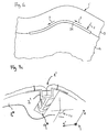
- FIG. 6 2 shows the underside of the first skin 3, the underside of the first skin 4 and the underside 24 of the retaining profile 2.
- the retaining profile 2 is surmounted by the composite of the first skin 3 and the second skin 4 in the first direction y, ie the direction of the course of the groove of the retaining profile 2.
- the composite part 1 "produced in this way is connected to a carrier, wherein the carrier has a As a result of this, the seam position with respect to the carrier is determined and the rejects are further reduced.
- Fig. 7a-c be different embodiments of a composite part according to the invention with a holding profile 2 as in the FIGS. 1 shown, but the functional seam 70 is not incorporated.
- the composite part 1 "'of Fig. 7a comprises a carrier 8 'made of natural fibers, which has a recess 9' for receiving the holding profile 2 " otherwise designated, the same numerals designate the same components as in the FIGS. 1 and 2 ,
- the same numerals designate the same components as in the FIGS. 1 and 2 .
- a sinking of the wings in the carrier is achieved, so that the wings close almost flush with the support surface.
- the milling must not be exactly planar, since the comparatively large contact surface of the underside of the wing compensates or corrects bumps. Even without milling, a satisfactory result is already achieved.
- the retaining profile consists of a one-piece extruded plastic profile of Shore A hardness of 55, the first and second skin 3, 4 are each made of leather. There is no further layer between the wearer and the skin. However, an additional foam layer can also be arranged as on the surface of the carrier. Suitable carrier materials are plastics such as polypropylene (PP) or glass fiber reinforced PP (PPLGF), natural fiber materials or polyurethane foams.
- PP polypropylene
- PPLGF glass fiber reinforced PP
- natural fiber materials or polyurethane foams.
- FIG. 7b A variant of a carrier 8 "of a composite part 1""is shown, which is provided outside the region of the recess with a spacer fabric 91.
- the carrier 8" itself consists of a natural fiber / plastic mixture.
- the natural fiber / plastic mixture projects as far as the visible side surface of the carrier in order to ensure sufficient stability of the recess when the holding profile is pressed into the recess Bottom of the wings directly on the natural fiber / plastic compound of the carrier.
- a further variant of a carrier 8 * is shown.
- Fig. 7c also discloses that a second direction x 'along the first direction y along which the wings extend must not be perpendicular to the mirror axis of symmetry of the holding profile, ie to the third direction z, but adapted according to the surface condition, ie the curvature of the composite part can.
- the length of a holding profile or the draft angle of the recess of the carrier is also dependent on the choice of material of the wearer. If a plastic such as PPLGF is selected as the material, the retaining profile or a journal of the retaining profile can have up to 3, preferably 2, superposed anchors and the journal can have a length between 3 mm and 10 mm. Accordingly, the depth of the recess of the carrier is chosen, which is greater than the composite length of the pin and the depth of the groove of the holding profile is.
- the draft angle can be between 90 ° +/- 30 °.
- the holding profile preferably has only one anchor, wherein the pin has a length between 2 mm and 6 mm and the depth of the recess is selected accordingly. Accordingly, the depth of the recess of the carrier is selected, which is greater than the composite length of the pin and the depth of the groove of the retaining profile.
- the draft angle can be between 90 ° +/- 15 °.
- the mass density of the carrier is less than 3000 g / m 2, preferably less than 2000 g / m 2, more preferably between 900 g / m 2 and 1400 or 1800 g / m 2.
Landscapes
- Engineering & Computer Science (AREA)
- Mechanical Engineering (AREA)
- Sewing Machines And Sewing (AREA)
- Lining Or Joining Of Plastics Or The Like (AREA)
- Vehicle Interior And Exterior Ornaments, Soundproofing, And Insulation (AREA)
Claims (14)
- Profilé de maintien (2 ; 2') avec une rainure (20 ; 20') limitée par des parois latérales (29 ; 29') et un fond (24), pour le positionnement d'une première et d'une deuxième membrane (3, 4), la rainure (20) s'étendant dans une première direction (y) et un axe étant raccordé au côté du fond (24) opposé à la rainure,
une première ailette (21 ; 21') prolongeant la première paroi latérale et une deuxième ailette (22 ; 22') prolongeant la deuxième paroi latérale et les ailettes s'étendant le long d'une deuxième direction (x) globalement perpendiculaire à la première direction, la première et la deuxième ailette (21, 22 ; 21', 22') s'étendant de l'extrémité ouverte de la rainure le long de la deuxième direction (x), caractérisé en ce qu'une portion (32) de la
première membrane (3) est reliée avec une première (21 ; 21') des au moins deux ailettes du profilé de maintien (2 ; 2') au moyen d'au moins une couture (5) comprenant au moins un fil et/ou
une portion (42) de la deuxième membrane (4) est reliée avec une deuxième (22, 22') de l'au moins deux ailettes du profilé de maintien (2 ; 2') au moyen d'une deuxième couture (6) comprenant au moins un fil. - Profilé de maintien selon la revendication 1, caractérisé en ce que l'axe (27') comprend au moins un ancrage (28').
- Profilé de maintien selon l'une des revendications précédentes, caractérisé en ce que la première et la deuxième ailette présentent une épaisseur d'ailette (21, 22 ; 21', 22') entre 0,05 mm et 1 mm, de préférence entre 0,2 mm et 0,6 mm et l'épaisseur de paroi de la première et de la deuxième ailette est de préférence essentiellement constante.
- Procédé de fabrication d'un élément composite (1 ; 1' ; 1" ; 1'" ; 1"") qui comprend les étapes suivantes :a) introduction d'une portion d'extrémité (31) d'une première membrane (3) et d'une portion d'extrémité (41) d'une deuxième membrane (4) dans une rainure (20 ; 20') s'étendant le long d'une première direction (y) et limitée par des parois latérales (29 ; 29') et un fond (24), d'un profilé de maintien (2 ; 2'), qui comprend au moins deux ailettes (21, 22 ; 21', 22'), qui prolongent les parois latérales et qui s'étendent d'une extrémité ouverte de la rainure, le long de la deuxième direction (x) perpendiculairement à la première direction ;caractérisé par l'étape supplémentaire suivante :b) liaison d'une portion (32), prolongeant la portion d'extrémité (31), de lapremière membrane (3) avec une première (21 ; 21') des au moins deux ailettes du profilé de maintien (2 ; 2') au moyen d'une première couture (5) comprenant au moins un fil, et/ouliaison d'une portion (42), prolongeant la portion d'extrémité (41), de la deuxième membrane (4) avec une deuxième (22 ; 22') des au moins deux ailettes du profilé de maintien (2 ; 2') au moyen d'une deuxième couture (6) comprenant au moins un fil (6).
- Procédé selon la revendication 4, caractérisé en ce que la première et la deuxième membranes (3, 4) sont reliées entre elles avec une couture fonctionnelle (7) disposée entre leurs portions (32, 42) respectives et leurs portions d'extrémité (31, 41) respectives, de préférence avant l'introduction des portions d'extrémité (31, 41) dans la rainure (20 ; 20').
- Procédé selon l'une des revendications 4 ou 5, caractérisé en ce que les portions d'extrémité (31, 41) de la première et de la deuxième membranes (3, 4) présentent une longueur entre 0,5 mm et 3 mm.
- Procédé selon l'une des revendications 4 à 6, caractérisé en ce que la première et la deuxième membranes (3, 4), reliées avec le profilé de maintien (2 ; 2'), dépassent du profilé de maintien (2 ; 2') dans la première direction (y).
- Procédé selon l'une des revendications 4 à 7, caractérisé en ce que, après l'introduction de la première couture fonctionnelle (70) dans la rainure (20 ; 20'), le profilé de maintien est inséré dans un évidement (9) d'un support (8) et le profilé de maintien (2 ; 2') est relié, de préférence par complémentarité de forme et/ou par liaison de matière avec le support (8).
- Procédé selon l'une des revendications 4 à 8, caractérisé en ce que le profilé de maintien (2 ; 2') est constitué d'une matière plastique qui présente une dureté Shore A entre 25 et 100, de préférence entre 50 et 100.
- Procédé selon l'une des revendications 4 à 9, caractérisé en ce que la première et/ou la deuxième membrane (3, 4) est constituée d'un cuir, d'un cuir artificiel, d'une matière plastique, d'un tissu ou d'un tricot.
- Procédé selon l'une des revendications 4 à 10, caractérisé en ce que le profilé de maintien et des parties optionnelles des portions d'extrémité sont raccourcies à une distance définie par rapport à l'extension de la première couture fonctionnelle.
- Élément composite (1 ; 1' ; 1" ; 1"'1 ; 1"") avec une première membrane (3), une deuxième membrane (4) et un profilé de maintien (2 ; 2') relié avec la première et la deuxième membranes au moyen d'une couture (70),
le profilé de maintien (2 ; 2') comprenant une rainure (20; 20') s'étendant dans une première direction (y) et limitée par des parois latérales (29 ; 29') et un fond (24), une portion d'extrémité (31) de la première membrane (3), une portion d'extrémité (41) de la deuxième membrane (4) et la couture, qui est conçue de préférence comme une première couture fonctionnelle (70) comprenant au moins un fil, étant disposées dans la rainure (20 ; 20'),
le profilé de maintien comprenant au moins deux ailettes, une ailette prolongeant la première paroi latérale et s'étendant de l'extrémité ouverte de la rainure le long d'une deuxième direction (x) essentiellement perpendiculaire à la première direction, caractérisé en ce que
une portion (32) de la première membrane (3) est reliée avec une première (21 ; 21') des au moins deux ailettes du profilé de maintien (2 ; 2') au moyen d'une première couture (5) comprenant au moins un fil et/ou
une portion (42) de la deuxième membrane (4) est reliée avec une deuxième (22 ; 22') des au moins deux ailettes (2 ; 2') au moyen d'une couture (6) comprenant au moins un fil. - Élément composite selon la revendication 12, caractérisé en ce qu'un support (9) comprend un évidement (8), le profilé de maintien (2 ; 2') étant inséré dans l'évidement (9).
- Élément composite selon la revendication 12, caractérisé en ce que l'évidement (9) du support (8) est conçu de façon à ce que l'au moins une ailette (21, 22) s'appuie à l'extérieur de l'évidement (9) contre la surface du support.
Priority Applications (1)
| Application Number | Priority Date | Filing Date | Title |
|---|---|---|---|
| EP10710248.5A EP2408649B1 (fr) | 2009-03-18 | 2010-03-18 | Profilé de retenue et pièce composite pour l'habillage d'un intérieur de véhicule automobile |
Applications Claiming Priority (5)
| Application Number | Priority Date | Filing Date | Title |
|---|---|---|---|
| DE200910013863 DE102009013863A1 (de) | 2009-03-18 | 2009-03-18 | Verbundteil zur Verkleidung von Kraftfahrzeuginnenräumen |
| DE200910013862 DE102009013862A1 (de) | 2009-03-18 | 2009-03-18 | Verbundteil zur Verkleidung von Kraftfahrzeuginnenräumen |
| EP09075335.1A EP2230132B1 (fr) | 2009-03-18 | 2009-07-27 | Pièce composite pour l'habillage d'intérieurs de véhicules automobiles |
| PCT/EP2010/001890 WO2010105855A2 (fr) | 2009-03-18 | 2010-03-18 | Profil de retenue et pièce composite pour l'habillage de l'habitacle d'un véhicule automobile |
| EP10710248.5A EP2408649B1 (fr) | 2009-03-18 | 2010-03-18 | Profilé de retenue et pièce composite pour l'habillage d'un intérieur de véhicule automobile |
Publications (2)
| Publication Number | Publication Date |
|---|---|
| EP2408649A2 EP2408649A2 (fr) | 2012-01-25 |
| EP2408649B1 true EP2408649B1 (fr) | 2016-10-12 |
Family
ID=41600793
Family Applications (2)
| Application Number | Title | Priority Date | Filing Date |
|---|---|---|---|
| EP09075335.1A Active EP2230132B1 (fr) | 2009-03-18 | 2009-07-27 | Pièce composite pour l'habillage d'intérieurs de véhicules automobiles |
| EP10710248.5A Active EP2408649B1 (fr) | 2009-03-18 | 2010-03-18 | Profilé de retenue et pièce composite pour l'habillage d'un intérieur de véhicule automobile |
Family Applications Before (1)
| Application Number | Title | Priority Date | Filing Date |
|---|---|---|---|
| EP09075335.1A Active EP2230132B1 (fr) | 2009-03-18 | 2009-07-27 | Pièce composite pour l'habillage d'intérieurs de véhicules automobiles |
Country Status (2)
| Country | Link |
|---|---|
| EP (2) | EP2230132B1 (fr) |
| WO (1) | WO2010105855A2 (fr) |
Cited By (2)
| Publication number | Priority date | Publication date | Assignee | Title |
|---|---|---|---|---|
| DE102019109390A1 (de) * | 2019-04-10 | 2020-10-15 | Dr. Ing. H.C. F. Porsche Aktiengesellschaft | Innenraumkomponente für ein Kraftfahrzeug |
| US11628781B2 (en) | 2021-05-14 | 2023-04-18 | Faurecia Interior Systems, Inc. | Vehicle interior panel and method of manufacture |
Families Citing this family (28)
| Publication number | Priority date | Publication date | Assignee | Title |
|---|---|---|---|---|
| DE102010045729A1 (de) | 2010-09-15 | 2012-03-15 | Faurecia Innenraum Systeme Gmbh | Verbundteil sowie Verfahren zur Herstellung eines Verbundteils |
| DE102010045719A1 (de) | 2010-09-15 | 2012-03-15 | Faurecia Innenraum Systeme Gmbh | Halteprofil zum Positionieren einer ersten und einer zweiten Haut, Verbundteil mit einer ersten und einer zweiten Haut sowie einem Halteprofil und Schneidevorrichtung zum Beschneiden eines Halteprofils |
| DE102010053149B4 (de) | 2010-11-30 | 2015-02-26 | Faurecia Innenraum Systeme Gmbh | Werkzeug zum Positionieren einer Haut |
| DE202010016550U1 (de) | 2010-12-09 | 2011-03-03 | Faurecia Innenraum Systeme Gmbh | Verbundteil mit Schweißverbindung |
| DE102011119320B4 (de) | 2011-11-17 | 2024-12-24 | Faurecia Innenraum Systeme Gmbh | Verkleidungsteil mit einem Halteprofil zum Positionieren einer zwei Dekorschichten verbindenden Naht |
| DE102012210734B9 (de) | 2012-06-25 | 2017-02-23 | Faurecia Innenraum Systeme Gmbh | Verfahren zur Kürzung eines Halteprofils, Verwendung einer Nähvorrichtung sowie Nähvorrichtung |
| DE102014225944A1 (de) | 2014-12-15 | 2016-06-16 | Faurecia Innenraum Systeme Gmbh | Formteil, Fahrzeuginnenverkleidungsteil sowie Vorrichtung und Verfahren zur Herstellung des Formteils bzw. des Fahrzeuginnenverkleidungsteils |
| HUE049212T2 (hu) * | 2015-01-20 | 2020-09-28 | Smp Deutschland Gmbh | Bõrkárpit-sablon |
| DE202015002525U1 (de) | 2015-04-08 | 2015-05-28 | Leather Components Vertriebs-Ug (Haftungsbeschränkt) | Fixierhilfe zum einfachen Fixieren von Nähkleidern auf Trägerteilen |
| DE102015226306A1 (de) | 2015-12-21 | 2017-06-22 | Faurecia Innenraum Systeme Gmbh | Halteprofil, Verwendung eines Halteprofils und Verbundteil |
| DE102016211650B4 (de) * | 2016-06-28 | 2025-02-27 | Faurecia Innenraum Systeme Gmbh | Verfahren zur Herstellung eines Formteils für ein Fahrzeuginnenverkleidungsteil und Formteil |
| DE102016217957A1 (de) | 2016-09-20 | 2018-03-22 | Faurecia Innenraum Systeme Gmbh | Verfahren zur Herstellung eines Bauteils zur Aufnahme eines Dekorteils für ein Fahrzeuginnenverkleidungsteil und Bauteil |
| KR101837964B1 (ko) * | 2017-07-21 | 2018-03-13 | 전학수 | 보조부를 포함하는 차량용 내장재 |
| CN109334586A (zh) * | 2017-08-24 | 2019-02-15 | 阿尔特汽车技术股份有限公司 | 内饰表皮缝纫线定位结构及其定位方法 |
| DE102017215206A1 (de) | 2017-08-30 | 2019-02-28 | Faurecia Innenraum Systeme Gmbh | Hautanordnung, Fahrzeuginnenverkleidungsteil und Verfahren zur Herstellung einer Hautanordnung |
| DE102017215205A1 (de) | 2017-08-30 | 2019-02-28 | Faurecia Innenraum Systeme Gmbh | Hautanordnung, Fahrzeuginnenverkleidungsteil und Verfahren zur Herstellung einer Hautanordnung |
| US12269384B2 (en) | 2021-03-31 | 2025-04-08 | Lear Corporation | Seat support |
| US12319183B2 (en) | 2021-03-31 | 2025-06-03 | Lear Corporation | Seat support |
| US11807143B2 (en) | 2021-12-02 | 2023-11-07 | Lear Corporation | Vehicle seating system and method for producing same |
| US12325168B2 (en) | 2021-12-20 | 2025-06-10 | Lear Corporation | System and method of making a mesh cushion |
| US12479143B2 (en) | 2021-12-20 | 2025-11-25 | Lear Corporation | System and method of making a mesh cushion |
| US12384094B2 (en) | 2022-03-08 | 2025-08-12 | Lear Corporation | Method for producing a vehicle interior component |
| US12454111B2 (en) | 2022-05-11 | 2025-10-28 | Lear Corporation | Tool to manufacture a cushion |
| US12509343B2 (en) | 2023-02-28 | 2025-12-30 | Lear Corporation | Automated trench manufacturing and assembly for attaching trim covers to a cushion assembly |
| US12325624B2 (en) | 2023-03-06 | 2025-06-10 | Lear Corporation | Seat assembly, cushion, and tool and method of forming |
| US12286044B2 (en) | 2023-05-12 | 2025-04-29 | Lear Corporation | Method and apparatus for producing a vehicle interior component |
| DK182040B1 (en) * | 2023-06-15 | 2025-06-11 | Lear Corp | SEAT ASSEMBLY, CLAMP AND MANUFACTURING METHOD |
| CN118166489A (zh) * | 2023-12-04 | 2024-06-11 | 常州新泉汽车零部件有限公司 | 一种带胶条的仪表台表皮缝纫、包覆自动生产工艺与设备 |
Family Cites Families (4)
| Publication number | Priority date | Publication date | Assignee | Title |
|---|---|---|---|---|
| JP4080671B2 (ja) * | 2000-02-07 | 2008-04-23 | 名古屋油化株式会社 | 多色内装材の製造方法 |
| DE102004053133A1 (de) * | 2004-10-29 | 2006-05-04 | Faurecia Innenraum Systeme Gmbh | Überzug zur Verkleidung von Kraftfahrzeug-Innenräumen und Formteil mit einem solchen Überzug |
| JP4851194B2 (ja) * | 2006-02-03 | 2012-01-11 | テイ・エス テック株式会社 | 車両用内装材及び該車両用内装材の製造方法 |
| JP2008213768A (ja) * | 2007-03-07 | 2008-09-18 | Toyoda Gosei Co Ltd | 表皮被覆品における表皮材の接合部固定構造 |
-
2009
- 2009-07-27 EP EP09075335.1A patent/EP2230132B1/fr active Active
-
2010
- 2010-03-18 WO PCT/EP2010/001890 patent/WO2010105855A2/fr not_active Ceased
- 2010-03-18 EP EP10710248.5A patent/EP2408649B1/fr active Active
Cited By (2)
| Publication number | Priority date | Publication date | Assignee | Title |
|---|---|---|---|---|
| DE102019109390A1 (de) * | 2019-04-10 | 2020-10-15 | Dr. Ing. H.C. F. Porsche Aktiengesellschaft | Innenraumkomponente für ein Kraftfahrzeug |
| US11628781B2 (en) | 2021-05-14 | 2023-04-18 | Faurecia Interior Systems, Inc. | Vehicle interior panel and method of manufacture |
Also Published As
| Publication number | Publication date |
|---|---|
| EP2230132B1 (fr) | 2016-05-25 |
| WO2010105855A3 (fr) | 2010-11-25 |
| EP2408649A2 (fr) | 2012-01-25 |
| EP2230132A1 (fr) | 2010-09-22 |
| WO2010105855A2 (fr) | 2010-09-23 |
Similar Documents
| Publication | Publication Date | Title |
|---|---|---|
| EP2408649B1 (fr) | Profilé de retenue et pièce composite pour l'habillage d'un intérieur de véhicule automobile | |
| DE69301162T2 (de) | Verfahren zur Herstellung eine Fasernverstärkung für ein Teil aus Verbundmaterial und Verbundteil aus einer solchen Verstärkung | |
| DE112012002886B4 (de) | Fahrzeuginnenraumkomponentennähverfahren und mit dem Verfahren erzeugtes Fahrzeuginnenraumverkleidungsstück | |
| DE112016001778B4 (de) | Strukturbaugruppe für eine Fahrzeugsitz-Rückenlehne | |
| DE112014006462B4 (de) | Gegossener Flächenhaftverschluss, Polsterkörper, Verfahren zur Herstellung eines Polsterkörpers und Gießform | |
| DE102011050003A1 (de) | Gelochtes Kunststoff-Formteil mit Dekormaterial sowie Vorrichtung und Verfahren zu dessen Herstellung | |
| DE102011075720A1 (de) | Trägerloses Interieurteil | |
| EP1651477B1 (fr) | Procede de travail d'une structure textile, structure textile, revetement et dispositif pourvu d'un tel revetement, notamment siege de vehicule | |
| DE102009013863A1 (de) | Verbundteil zur Verkleidung von Kraftfahrzeuginnenräumen | |
| WO2001032406A1 (fr) | Procede et dispositif de production de demi-produits a structure de renforcement par fibres pour la fabrication de composants composites fibres-plastiques | |
| DE102010045729A1 (de) | Verbundteil sowie Verfahren zur Herstellung eines Verbundteils | |
| DE102013222356B4 (de) | Verfahren zum Herstellen eines integralen Faserverbundbauteils mit Einlegeelement | |
| EP3483002A1 (fr) | Housse de siège, siège de véhicule et procédé de fabrication d'une housse de siège | |
| DE102008012431B4 (de) | Verfahren zur Herstellung eines Verbundteils mit mehrteiliger Deckschicht und Verbundteil | |
| EP3755516B1 (fr) | Élément structural comprenant plusieurs plaques de composite thermoplastique renforcé de fibres et son procédé de fabrication | |
| DE19629044C2 (de) | Flächige Struktur aus Faserverbundwerkstoffen und Verfahren zu ihrer Herstellung | |
| DE102011119320B4 (de) | Verkleidungsteil mit einem Halteprofil zum Positionieren einer zwei Dekorschichten verbindenden Naht | |
| DE102009013862A1 (de) | Verbundteil zur Verkleidung von Kraftfahrzeuginnenräumen | |
| DE102014111538A1 (de) | Verfahren zum Ausbilden einer Ziernaht | |
| DE102010045719A1 (de) | Halteprofil zum Positionieren einer ersten und einer zweiten Haut, Verbundteil mit einer ersten und einer zweiten Haut sowie einem Halteprofil und Schneidevorrichtung zum Beschneiden eines Halteprofils | |
| DE102017121659A1 (de) | Innenteil und verfahren zum herstellen desselben | |
| DE102008060817A1 (de) | Innenverkleidungsteil mit Nahtpositionierung | |
| DE102011109514B4 (de) | Verbundteil | |
| DE102017215206A1 (de) | Hautanordnung, Fahrzeuginnenverkleidungsteil und Verfahren zur Herstellung einer Hautanordnung | |
| DE102018214016B4 (de) | Fahrradsattel |
Legal Events
| Date | Code | Title | Description |
|---|---|---|---|
| PUAI | Public reference made under article 153(3) epc to a published international application that has entered the european phase |
Free format text: ORIGINAL CODE: 0009012 |
|
| 17P | Request for examination filed |
Effective date: 20111017 |
|
| AK | Designated contracting states |
Kind code of ref document: A2 Designated state(s): AT BE BG CH CY CZ DE DK EE ES FI FR GB GR HR HU IE IS IT LI LT LU LV MC MK MT NL NO PL PT RO SE SI SK SM TR |
|
| DAX | Request for extension of the european patent (deleted) | ||
| 17Q | First examination report despatched |
Effective date: 20150416 |
|
| GRAP | Despatch of communication of intention to grant a patent |
Free format text: ORIGINAL CODE: EPIDOSNIGR1 |
|
| INTG | Intention to grant announced |
Effective date: 20160421 |
|
| GRAS | Grant fee paid |
Free format text: ORIGINAL CODE: EPIDOSNIGR3 |
|
| GRAA | (expected) grant |
Free format text: ORIGINAL CODE: 0009210 |
|
| AK | Designated contracting states |
Kind code of ref document: B1 Designated state(s): AT BE BG CH CY CZ DE DK EE ES FI FR GB GR HR HU IE IS IT LI LT LU LV MC MK MT NL NO PL PT RO SE SI SK SM TR |
|
| REG | Reference to a national code |
Ref country code: GB Ref legal event code: FG4D Free format text: NOT ENGLISH |
|
| REG | Reference to a national code |
Ref country code: CH Ref legal event code: EP |
|
| REG | Reference to a national code |
Ref country code: AT Ref legal event code: REF Ref document number: 836183 Country of ref document: AT Kind code of ref document: T Effective date: 20161015 |
|
| REG | Reference to a national code |
Ref country code: IE Ref legal event code: FG4D Free format text: LANGUAGE OF EP DOCUMENT: GERMAN |
|
| REG | Reference to a national code |
Ref country code: DE Ref legal event code: R096 Ref document number: 502010012550 Country of ref document: DE |
|
| REG | Reference to a national code |
Ref country code: LT Ref legal event code: MG4D |
|
| REG | Reference to a national code |
Ref country code: NL Ref legal event code: MP Effective date: 20161012 |
|
| REG | Reference to a national code |
Ref country code: FR Ref legal event code: PLFP Year of fee payment: 8 |
|
| PG25 | Lapsed in a contracting state [announced via postgrant information from national office to epo] |
Ref country code: LV Free format text: LAPSE BECAUSE OF FAILURE TO SUBMIT A TRANSLATION OF THE DESCRIPTION OR TO PAY THE FEE WITHIN THE PRESCRIBED TIME-LIMIT Effective date: 20161012 |
|
| PG25 | Lapsed in a contracting state [announced via postgrant information from national office to epo] |
Ref country code: SE Free format text: LAPSE BECAUSE OF FAILURE TO SUBMIT A TRANSLATION OF THE DESCRIPTION OR TO PAY THE FEE WITHIN THE PRESCRIBED TIME-LIMIT Effective date: 20161012 Ref country code: GR Free format text: LAPSE BECAUSE OF FAILURE TO SUBMIT A TRANSLATION OF THE DESCRIPTION OR TO PAY THE FEE WITHIN THE PRESCRIBED TIME-LIMIT Effective date: 20170113 Ref country code: LT Free format text: LAPSE BECAUSE OF FAILURE TO SUBMIT A TRANSLATION OF THE DESCRIPTION OR TO PAY THE FEE WITHIN THE PRESCRIBED TIME-LIMIT Effective date: 20161012 Ref country code: NO Free format text: LAPSE BECAUSE OF FAILURE TO SUBMIT A TRANSLATION OF THE DESCRIPTION OR TO PAY THE FEE WITHIN THE PRESCRIBED TIME-LIMIT Effective date: 20170112 |
|
| PG25 | Lapsed in a contracting state [announced via postgrant information from national office to epo] |
Ref country code: ES Free format text: LAPSE BECAUSE OF FAILURE TO SUBMIT A TRANSLATION OF THE DESCRIPTION OR TO PAY THE FEE WITHIN THE PRESCRIBED TIME-LIMIT Effective date: 20161012 Ref country code: HR Free format text: LAPSE BECAUSE OF FAILURE TO SUBMIT A TRANSLATION OF THE DESCRIPTION OR TO PAY THE FEE WITHIN THE PRESCRIBED TIME-LIMIT Effective date: 20161012 Ref country code: PL Free format text: LAPSE BECAUSE OF FAILURE TO SUBMIT A TRANSLATION OF THE DESCRIPTION OR TO PAY THE FEE WITHIN THE PRESCRIBED TIME-LIMIT Effective date: 20161012 Ref country code: NL Free format text: LAPSE BECAUSE OF FAILURE TO SUBMIT A TRANSLATION OF THE DESCRIPTION OR TO PAY THE FEE WITHIN THE PRESCRIBED TIME-LIMIT Effective date: 20161012 Ref country code: IS Free format text: LAPSE BECAUSE OF FAILURE TO SUBMIT A TRANSLATION OF THE DESCRIPTION OR TO PAY THE FEE WITHIN THE PRESCRIBED TIME-LIMIT Effective date: 20170212 Ref country code: FI Free format text: LAPSE BECAUSE OF FAILURE TO SUBMIT A TRANSLATION OF THE DESCRIPTION OR TO PAY THE FEE WITHIN THE PRESCRIBED TIME-LIMIT Effective date: 20161012 Ref country code: PT Free format text: LAPSE BECAUSE OF FAILURE TO SUBMIT A TRANSLATION OF THE DESCRIPTION OR TO PAY THE FEE WITHIN THE PRESCRIBED TIME-LIMIT Effective date: 20170213 |
|
| REG | Reference to a national code |
Ref country code: DE Ref legal event code: R097 Ref document number: 502010012550 Country of ref document: DE |
|
| PG25 | Lapsed in a contracting state [announced via postgrant information from national office to epo] |
Ref country code: CZ Free format text: LAPSE BECAUSE OF FAILURE TO SUBMIT A TRANSLATION OF THE DESCRIPTION OR TO PAY THE FEE WITHIN THE PRESCRIBED TIME-LIMIT Effective date: 20161012 Ref country code: DK Free format text: LAPSE BECAUSE OF FAILURE TO SUBMIT A TRANSLATION OF THE DESCRIPTION OR TO PAY THE FEE WITHIN THE PRESCRIBED TIME-LIMIT Effective date: 20161012 Ref country code: RO Free format text: LAPSE BECAUSE OF FAILURE TO SUBMIT A TRANSLATION OF THE DESCRIPTION OR TO PAY THE FEE WITHIN THE PRESCRIBED TIME-LIMIT Effective date: 20161012 Ref country code: SK Free format text: LAPSE BECAUSE OF FAILURE TO SUBMIT A TRANSLATION OF THE DESCRIPTION OR TO PAY THE FEE WITHIN THE PRESCRIBED TIME-LIMIT Effective date: 20161012 Ref country code: EE Free format text: LAPSE BECAUSE OF FAILURE TO SUBMIT A TRANSLATION OF THE DESCRIPTION OR TO PAY THE FEE WITHIN THE PRESCRIBED TIME-LIMIT Effective date: 20161012 |
|
| PLBE | No opposition filed within time limit |
Free format text: ORIGINAL CODE: 0009261 |
|
| STAA | Information on the status of an ep patent application or granted ep patent |
Free format text: STATUS: NO OPPOSITION FILED WITHIN TIME LIMIT |
|
| PG25 | Lapsed in a contracting state [announced via postgrant information from national office to epo] |
Ref country code: BG Free format text: LAPSE BECAUSE OF FAILURE TO SUBMIT A TRANSLATION OF THE DESCRIPTION OR TO PAY THE FEE WITHIN THE PRESCRIBED TIME-LIMIT Effective date: 20170112 Ref country code: IT Free format text: LAPSE BECAUSE OF FAILURE TO SUBMIT A TRANSLATION OF THE DESCRIPTION OR TO PAY THE FEE WITHIN THE PRESCRIBED TIME-LIMIT Effective date: 20161012 Ref country code: SM Free format text: LAPSE BECAUSE OF FAILURE TO SUBMIT A TRANSLATION OF THE DESCRIPTION OR TO PAY THE FEE WITHIN THE PRESCRIBED TIME-LIMIT Effective date: 20161012 |
|
| 26N | No opposition filed |
Effective date: 20170713 |
|
| REG | Reference to a national code |
Ref country code: CH Ref legal event code: PL |
|
| PG25 | Lapsed in a contracting state [announced via postgrant information from national office to epo] |
Ref country code: MC Free format text: LAPSE BECAUSE OF FAILURE TO SUBMIT A TRANSLATION OF THE DESCRIPTION OR TO PAY THE FEE WITHIN THE PRESCRIBED TIME-LIMIT Effective date: 20161012 Ref country code: SI Free format text: LAPSE BECAUSE OF FAILURE TO SUBMIT A TRANSLATION OF THE DESCRIPTION OR TO PAY THE FEE WITHIN THE PRESCRIBED TIME-LIMIT Effective date: 20161012 |
|
| REG | Reference to a national code |
Ref country code: IE Ref legal event code: MM4A |
|
| PG25 | Lapsed in a contracting state [announced via postgrant information from national office to epo] |
Ref country code: LU Free format text: LAPSE BECAUSE OF NON-PAYMENT OF DUE FEES Effective date: 20170318 |
|
| REG | Reference to a national code |
Ref country code: FR Ref legal event code: PLFP Year of fee payment: 9 |
|
| PG25 | Lapsed in a contracting state [announced via postgrant information from national office to epo] |
Ref country code: CH Free format text: LAPSE BECAUSE OF NON-PAYMENT OF DUE FEES Effective date: 20170331 Ref country code: IE Free format text: LAPSE BECAUSE OF NON-PAYMENT OF DUE FEES Effective date: 20170318 Ref country code: LI Free format text: LAPSE BECAUSE OF NON-PAYMENT OF DUE FEES Effective date: 20170331 |
|
| REG | Reference to a national code |
Ref country code: BE Ref legal event code: MM Effective date: 20170331 |
|
| REG | Reference to a national code |
Ref country code: AT Ref legal event code: MM01 Ref document number: 836183 Country of ref document: AT Kind code of ref document: T Effective date: 20170318 |
|
| PG25 | Lapsed in a contracting state [announced via postgrant information from national office to epo] |
Ref country code: BE Free format text: LAPSE BECAUSE OF NON-PAYMENT OF DUE FEES Effective date: 20170331 |
|
| PG25 | Lapsed in a contracting state [announced via postgrant information from national office to epo] |
Ref country code: AT Free format text: LAPSE BECAUSE OF NON-PAYMENT OF DUE FEES Effective date: 20170318 |
|
| PG25 | Lapsed in a contracting state [announced via postgrant information from national office to epo] |
Ref country code: MT Free format text: LAPSE BECAUSE OF FAILURE TO SUBMIT A TRANSLATION OF THE DESCRIPTION OR TO PAY THE FEE WITHIN THE PRESCRIBED TIME-LIMIT Effective date: 20161012 |
|
| PG25 | Lapsed in a contracting state [announced via postgrant information from national office to epo] |
Ref country code: HU Free format text: LAPSE BECAUSE OF FAILURE TO SUBMIT A TRANSLATION OF THE DESCRIPTION OR TO PAY THE FEE WITHIN THE PRESCRIBED TIME-LIMIT; INVALID AB INITIO Effective date: 20100318 |
|
| PG25 | Lapsed in a contracting state [announced via postgrant information from national office to epo] |
Ref country code: CY Free format text: LAPSE BECAUSE OF NON-PAYMENT OF DUE FEES Effective date: 20161012 |
|
| PG25 | Lapsed in a contracting state [announced via postgrant information from national office to epo] |
Ref country code: MK Free format text: LAPSE BECAUSE OF FAILURE TO SUBMIT A TRANSLATION OF THE DESCRIPTION OR TO PAY THE FEE WITHIN THE PRESCRIBED TIME-LIMIT Effective date: 20161012 |
|
| PG25 | Lapsed in a contracting state [announced via postgrant information from national office to epo] |
Ref country code: TR Free format text: LAPSE BECAUSE OF FAILURE TO SUBMIT A TRANSLATION OF THE DESCRIPTION OR TO PAY THE FEE WITHIN THE PRESCRIBED TIME-LIMIT Effective date: 20161012 |
|
| PGFP | Annual fee paid to national office [announced via postgrant information from national office to epo] |
Ref country code: GB Payment date: 20260219 Year of fee payment: 17 |
|
| PGFP | Annual fee paid to national office [announced via postgrant information from national office to epo] |
Ref country code: DE Payment date: 20260219 Year of fee payment: 17 |
|
| PGFP | Annual fee paid to national office [announced via postgrant information from national office to epo] |
Ref country code: FR Payment date: 20260219 Year of fee payment: 17 |