EP2409082B1 - Dispositif destiné au montage d'un élément de bouclier thermique - Google Patents
Dispositif destiné au montage d'un élément de bouclier thermique Download PDFInfo
- Publication number
- EP2409082B1 EP2409082B1 EP20100702474 EP10702474A EP2409082B1 EP 2409082 B1 EP2409082 B1 EP 2409082B1 EP 20100702474 EP20100702474 EP 20100702474 EP 10702474 A EP10702474 A EP 10702474A EP 2409082 B1 EP2409082 B1 EP 2409082B1
- Authority
- EP
- European Patent Office
- Prior art keywords
- heat shield
- screw
- shield element
- mounting device
- mounting
- Prior art date
- Legal status (The legal status is an assumption and is not a legal conclusion. Google has not performed a legal analysis and makes no representation as to the accuracy of the status listed.)
- Not-in-force
Links
- 238000000034 method Methods 0.000 claims description 8
- 239000007789 gas Substances 0.000 claims description 5
- 239000000567 combustion gas Substances 0.000 claims description 4
- 239000000446 fuel Substances 0.000 claims 1
- 239000007788 liquid Substances 0.000 claims 1
- 239000000919 ceramic Substances 0.000 description 5
- 238000002485 combustion reaction Methods 0.000 description 5
- 238000001816 cooling Methods 0.000 description 4
- 101100441413 Caenorhabditis elegans cup-15 gene Proteins 0.000 description 3
- 239000012809 cooling fluid Substances 0.000 description 3
- 230000000712 assembly Effects 0.000 description 2
- 238000000429 assembly Methods 0.000 description 2
- 238000010276 construction Methods 0.000 description 2
- 239000004575 stone Substances 0.000 description 2
- 230000008719 thickening Effects 0.000 description 2
- 238000013022 venting Methods 0.000 description 2
- 241001295925 Gegenes Species 0.000 description 1
- 230000006978 adaptation Effects 0.000 description 1
- 239000002390 adhesive tape Substances 0.000 description 1
- 230000008878 coupling Effects 0.000 description 1
- 238000010168 coupling process Methods 0.000 description 1
- 238000005859 coupling reaction Methods 0.000 description 1
- 230000001419 dependent effect Effects 0.000 description 1
- 230000000994 depressogenic effect Effects 0.000 description 1
- 239000013013 elastic material Substances 0.000 description 1
- 239000000834 fixative Substances 0.000 description 1
- 239000002184 metal Substances 0.000 description 1
Images
Classifications
-
- F—MECHANICAL ENGINEERING; LIGHTING; HEATING; WEAPONS; BLASTING
- F23—COMBUSTION APPARATUS; COMBUSTION PROCESSES
- F23R—GENERATING COMBUSTION PRODUCTS OF HIGH PRESSURE OR HIGH VELOCITY, e.g. GAS-TURBINE COMBUSTION CHAMBERS
- F23R3/00—Continuous combustion chambers using liquid or gaseous fuel
- F23R3/007—Continuous combustion chambers using liquid or gaseous fuel constructed mainly of ceramic components
-
- F—MECHANICAL ENGINEERING; LIGHTING; HEATING; WEAPONS; BLASTING
- F23—COMBUSTION APPARATUS; COMBUSTION PROCESSES
- F23M—CASINGS, LININGS, WALLS OR DOORS SPECIALLY ADAPTED FOR COMBUSTION CHAMBERS, e.g. FIREBRIDGES; DEVICES FOR DEFLECTING AIR, FLAMES OR COMBUSTION PRODUCTS IN COMBUSTION CHAMBERS; SAFETY ARRANGEMENTS SPECIALLY ADAPTED FOR COMBUSTION APPARATUS; DETAILS OF COMBUSTION CHAMBERS, NOT OTHERWISE PROVIDED FOR
- F23M5/00—Casings; Linings; Walls
- F23M5/04—Supports for linings
-
- F—MECHANICAL ENGINEERING; LIGHTING; HEATING; WEAPONS; BLASTING
- F23—COMBUSTION APPARATUS; COMBUSTION PROCESSES
- F23R—GENERATING COMBUSTION PRODUCTS OF HIGH PRESSURE OR HIGH VELOCITY, e.g. GAS-TURBINE COMBUSTION CHAMBERS
- F23R2900/00—Special features of, or arrangements for continuous combustion chambers; Combustion processes therefor
- F23R2900/00017—Assembling combustion chamber liners or subparts
Definitions
- the invention relates to a mounting device for mounting a heat shield element, a method for mounting a heat shield element and a use of the mounting device with the mentioned in the preamble of each independent claims features.
- High performance ceramic heat shields are used in many engineering applications to withstand temperatures up to 1600 degrees Celsius.
- the heat shields of turbine engines such as gas turbines and turbine engines, such as those used in power-generating power plants and in larger aircraft, have correspondingly large shielded by heat shields surfaces inside their combustion chambers.
- the shield must be composed of a plurality of individual ceramic heat shield elements spaced apart from one another with sufficient clearance. This gap provides the heat shield elements with sufficient space for thermal expansion.
- a cooling fluid in the form of cooling air is blown through cooling passages as an effective countermeasure through the gaps in the direction of the combustion chamber.
- This cooling air is also used to selectively blow the metal brackets, with which the ceramic heat shield elements (CHS, Ceramic Heat Shields) are clamped to the support structure, and thus to cool.
- CHS Ceramic Heat Shields
- brackets In order to carry out the brackets as simply and integrally as possible, a construction is known in which these brackets on the one hand in the support structure encircling circular and parallel groove inserted and on the other hand clamped with trained gripping portions in holder grooves be formed in lateral edges of the ceramic heat shield elements.
- the heat shield elements are successively inserted with the holders in the grooves of the support structure, wherein the trailing elements obstruct the previously positioned in their positions.
- a circular series of heat shield elements can be formed in a combustion chamber of a gas turbine.
- the last remaining heat shield element can no longer be mounted in this way because the mutually present adjacent heat shield elements block a tangentially directed assembly movement.
- a last heat shield element is referred to as a dummy plate or dummy. Consequently, solutions are used with screws for attaching the last heat shield element, which allow mounting of the heat shield element in the direction of the surface normal of the support structure.
- a known screw used for this purpose four screws which engage in the recess formed in lateral edges of the heat shield element for this purpose.
- This solution is often disadvantaged because the assembly brings a handling problem with it.
- the handling of the four screws enforces, for example, the use of fixatives such as bonding or adhesive tape, which are not reliable, so that the screws can be lost and must necessarily be found because of high risk of damage.
- an overhead mounting unfavorable because the screws can tilt by fixing with tape and thus can not be inserted into the holes provided. Since this is the last heat shield element, the screw can not be positioned by hand, but must be threaded into the holes using an Allen key - without sight.
- EP 1 701 095 A1 and EP 0 558 540 B1 describe by way of example a heat shield as described above with the described advantages and disadvantages.
- the heat shield elements are often referred to as stones and retaining elements holding them stone holder.
- EP 1555 443 describes a device for mounting a heat shield element.
- the object of the present invention is to make the mounting of a heat shield element in the direction of the surface normal of the support structure of a heat shield constructed from a plurality of heat shield elements safe and uncomplicated.
- the invention according to a first aspect of a mounting device for mounting a planar-shaped heat shield element of a plurality of adjacently arranged heat shield elements having heat shield by means of at least one screw on a support structure.
- the mounting direction in the direction of the surface normal of the support structure.
- the heat shield element has four openings for passing through four screwdrivers.
- a frame is provided with means for holding four screwing tools and at least one holding device for holding the heat shield element to the frame, such that the position of the four screwing tools and at least one holding device with respect to each other is maintained.
- the holding device for holding the heat shield element to the frame is designed as a suction cup with which a good suction connection can be achieved on the usually smooth surface of the heat shield element.
- the holding device for holding the heat shield element to the frame can be firmly connected to the frame.
- the holding device for holding the heat shield element to the frame with the frame can be connected in height adjustable. This allows an adaptation of the mounting device to the task.
- At least one means for holding at least one screwing tool is designed to be rotatable and / or tiltable and / or translationally displaceable relative to the frame.
- the means for holding at least one screwing tool is preferably designed as a ball joint, and the ball joint is acted upon by a defined predetermined stiffness or friction, whereby the screwing tool is flexibly adjustable and at the same time fixable in an reached position.
- the mounting device according to the invention is adapted to mount existing dummy heat shield elements with four screw connections when four screwing tools are provided for four respectively corresponding fastening screws.
- the four screwdrivers are equipped with a handle for manual operation of the screwdriving tools.
- This handle is designed for example in the simplest case as a cylindrical thickening of the head portion of the screwing.
- each screwing tool with its tool tip can be inserted into a recess formed in the head of a fastening screw mold cavity.
- the shape of the recess corresponding to the screw fastening screw of the screw of the heat shield element is preferably designed as a Allen, cross or transverse slot coupling or a differently formed engagement recess.
- the objects according to the invention are achieved by a method for mounting a heat shield element with the aid of a mounting device according to a preferred embodiment described above.
- the objects according to the invention are achieved by using the mounting device for mounting a last heat shield element of a heat shield, which terminates a series of preassembled neighboring heat shield elements.
- the heat shield is preferably used for lining a wall of a turbine engine which has been flown by hot combustion gases and which can be designed, in particular, as a gas turbine.
- turbine engines are used as drive units of power generators in power plants or as engines in large aircraft.
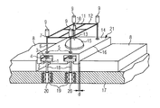
- the preferred embodiment of the mounting device according to the invention shown in Figure 1 is mounted on a heat shield element 14 of known construction.
- the heat shield element 14 is designed for vertical screwing to the support structure 17 and has for this purpose on two opposite side edges in each case two recesses 4, which are preferably rectangular in this case, so that they are respectively inserted into them discs or angle plates 2 are fixed against rotation ,
- Each recess 4 further has a lateral recess 1, in which the rod body of a fastening screw 18 is inserted laterally.
- the fastening screw 18 with the disk or the Wikelblech 2 can thus be inserted laterally into the lateral recess 1 and recess 4.
- a mold cavity for receiving a correspondingly shaped tool tip of a screwing tool is provided in the head of the fastening screw 18.
- This mold recess and the tool tip is preferably designed as one of the known Inbusstecktagenen, but may also have other shapes, such as cross or transverse slot.
- the diameter of this access opening 5 is substantially smaller than the diameter of the head 2 of the fastening screw 18 and is dimensioned such that it is sufficient to allow a screwing tool 6 to pass.
- hot combustion gases therefore pass only to a limited extent through the minimized in size access openings 5 in the wells 4 to the metallic discs 2 and heads 3 of the mounting screws 18.
- the wells 4 are flushed by the cooling fluid through the intermediate column d is blown from the support structure 17 into the combustion chamber to lock the wells 4 against the entry of hot gas.
- a part of the cooling fluid which is usually present as cooling air, can also pass through the access opening 5 into the combustion chamber.
- the intermediate gap d is provided, the thermal Extension of individual Hitzschild elements 8, 14 to provide sufficient space.
- Each fastening screw 18 is screwed into a screw connection in the support structure 17, which in the present example is designed in each case as a cup spring assembly 19.
- a threaded nut (not shown) serves to compress the disc spring assembly 19.
- the biased plate spring assemblies 19 provide a resiliently yielding attachment of the heat shield element 14, which is required to z. B. due to thermal and thermoacoustic conditions induced movements compensate.
- the four mounting screws 18 must be inserted laterally with the discs 2 in the respective lateral recesses 4 and recesses 1 and secured against falling out during assembly.
- the mounting device has a frame 12, which has, for example, a holding cross 11 as a centrally arranged carrier. In the center of the holding cross 11 is perpendicular to the frame 12, a rod 13 as a holding device for a suction cup 15 fixed or arranged height-adjustable in a preferred embodiment.
- the height adjustment can be realized for example by means of a thread applied to the rod 13.
- a handle 10 in the form of a cylindrical thickening serves to rotate the rod 13 and thus the height adjustment of the holding device 15th
- each have a screwing tool 6 is attached, wherein the positions of these screwing tools 6 are selected so that they correspond to the positions of the four screw connections in the support structure 17.
- Each screwing tool 6 is preferably tiltable, rotatable and height-adjustable or arranged vertically displaceable in the respective corner region of the frame 12. This is carried out in a preferred embodiment, for example by a ball joint, in which the screwing 6 is also arranged vertically translationally displaceable. Preferably, all movements are acted upon by a preset friction with a desired stiffness, which equally a free movement of the screwing tool for adjusting the position for rotating the screwing tool 6 and for moving the screwing tool 6 in height, as well as a fixation in an reached position is possible , By such a fixation, the operator can insert one after the other all four screwdrivers 6 in the respective heads 2 of the mounting screws, without having to hold all four at the same time.
- Each screwing tool 6 has at its outer end a handle 9, which facilitates the manual handling of the screwing tool 6.
- An assembly process is designed, for example, such that the operator first inserts a heat shield element 14 with the four fastening screws with respective disks 2 in each of the four lateral recesses 4 and recesses 1 and preferably positioned with the hot side 21 upwards.
- the mounting device preferably from above with the four screwdrivers, one after the other in each case an access opening 5 and puts the respective tool tip into the mold cavity of the head 3 of the mounting screw 18.
- the operator fits the Height of the rod 13 such that the suction cup 15 comes into contact with the hot side 21 of the heat shield element 14 and a suction connection is formed by pressing the suction cup.
- the frame 12 can be depressed, whereby the screwing tools 6 are moved in their brackets against the frictional force.
- the suction cup 15 are brought by pressing into a suction connection with the hot side 21 of the heat shield element 14 and then the individual screwing 6 are inserted into their brackets by tilting, turning and moving in the heads 2 of the mounting screws.
- the heat shield element 14 mounted in this way on the mounting device can now be lifted by a single operator and inserted in an arbitrarily aligned mounting position between preassembled adjacent heat shields 8.
- the operator can comfortably thread one after the other, the fastening screws 18 by tilting, turning and moving the screwdrivers 6 in the respective plate spring assemblies 19 and the threaded connection by screwing the screwdrivers 6 as far forward, as this allow the manually generated torques.
- the mounting device can be removed by releasing the suction cup made of an elastic material.
- the suction cup for example, have a venting and venting valve with lever operation or simply raised manually.
- the operator can tighten the mounting bolts 18 to a predefined torque using a torque wrench.
Landscapes
- Engineering & Computer Science (AREA)
- Chemical & Material Sciences (AREA)
- Combustion & Propulsion (AREA)
- Mechanical Engineering (AREA)
- General Engineering & Computer Science (AREA)
- Ceramic Engineering (AREA)
- Cooling Or The Like Of Electrical Apparatus (AREA)
- Connection Of Plates (AREA)
- Thermal Insulation (AREA)
- Heat-Exchange Devices With Radiators And Conduit Assemblies (AREA)
Claims (11)
- Dispositif ( 1 ) de montage ayant au moins un outil ( 6 ) de boulonnage pour le montage d'un élément ( 14 ) de bouclier thermique, constitué à la manière d'une surface, d'un bouclier thermique ayant une pluralité d'éléments de bouclier thermique disposés en étant voisins, à l'aide d'au moins un boulonnage ( 18 ) dans la direction d'une normale à la surface d'une structure ( 17 ) porteuse, les éléments ( 14 ) du bouclier thermique ayant au moins une ouverture ( 5 ) d'accès pour la traversée du au moins un outil ( 6 ) de boulonnage, caractérisé par
un cadre ( 12 ) ayant des moyens de maintien du au moins un outil ( 6 ) de boulonnage et d'au moins un dispositif ( 13, 15 ) de maintien constitué pour maintenir un élément ( 14 ) du bouclier thermique sur le cadre ( 12 ), de manière à pouvoir conserver la position du au moins un outil ( 6 ) de boulonnage et du au moins un dispositif ( 13, 15 ) de maintien l'un par rapport à l'autre, le au moins un outil ( 6 ) de boulonnage pouvant, dans sa fixation par sa pointe d'outil, être enfilé dans une cavité de forme formée dans la tête ( 3 ) d'un boulonnage ( 18 ), et le dispositif ( 13, 15 ) de maintien étant, pour maintenir l'élément ( 14 ) du bouclier thermique sur le cadre ( 12 ), réalisé sous la forme d'une ventouse ( 15 ) et au moins un moyen de maintien d'au moins un outil ( 6 ) de boulonnage étant réalisé tournant et/ou basculant et/ou déplaçable en translation par rapport au cadre ( 12 ), et il est prévu quatre outils ( 6 ) de boulonnage pour quatre boulons de fixation correspondantes respectivement et/ou paquets ( 19 ) de ressorts à disque. - Dispositif de montage suivant la revendication 1,
caractérisé en ce que
le dispositif ( 13 ) de maintien, pour maintenir l'élément ( 14 ) du bouclier thermique sur le cadre ( 12 ), est relié fixement au cadre ( 12 ). - Dispositif de montage suivant l'une des revendications précédentes,
caractérisé en ce que
le dispositif ( 13, 15 ) de maintien est, pour la fixation de l'élément ( 14 ) du bouclier thermique au cadre ( 12 ), réglable en hauteur avec le cadre ( 12 ). - Dispositif de montage suivant l'une des revendications précédentes,
caractérisé en ce que
le moyen de maintien d'au moins un outil ( 6 ) de boulonnage est réalisé sous la forme d'une rotule ( 7 ). - Dispositif de montage suivant la revendication 4,
caractérisé en ce que
la rotule ( 7 ) est soumise à des épreuves de dureté et/ou à un frottement défini donné à l'avance, grâce à quoi l'outil ( 6 ) de boulonnage peut être déplacé et immobilisé dans une position atteinte. - Dispositif de montage suivant l'une des revendications précédentes,
caractérisé en ce que
les outils ( 6 ) de boulonnage sont équipés d'une poignée ( 9 ) pour l'actionnement manuel. - Dispositif de montage suivant les revendications 1 à 6,
caractérisé en ce que
la cavité de forme du boulon ( 18 ) de fixation correspondant à l'outil ( 6 ) de boulonnage du au moins un boulonnage ( 18 ) de l'élément ( 14 ) du bouclier thermique est constituée sous la forme d'une fente à six pans, cruciforme ou transversale ou d'une cavité de pénétration autrement constituée. - Procédé de montage d'un élément de bouclier thermique à l'aide d'un dispositif de montage suivant l'une des revendications précédentes,
caractérisé en ce que- on enfile le au moins un boulon ( 18 ) de fixation de l'élément ( 14 ) de bouclier thermique comme boulonnage dans un évidement ( 1 ) et/ou dans une cavité ( 4 ) prévue pour le boulon ( 18 ) de fixation,- on met la au moins une ventouse ( 15 ) du dispositif ( 13, 15 ) de maintien pour la fixation de l'élément ( 14 ) du bouclier thermique sur le cadre ( 12 ) du dispositif de montage en l'appliquant suivant une liaison par aspiration à la surface du côté ( 21 ) chaud de l'élément ( 14 ) du bouclier thermique,- on enfile le au moins un outil ( 6 ) de boulonnage dans la cavité de forme constituée dans la tête ( 3 ) du boulon ( 18 ) de fixation,- on met, dans la position qui lui est prévue, l'élément ( 14 ) du bouclier thermique avec le dispositif de montage qui lui est adjoint, suivant un déplacement de montage dirigé suivant une normale à la surface de la structure ( 17 ) porteuse du bouclier thermique et- on introduit le au moins un boulon ( 18 ) de fixation, à l'aide de l'outil ( 6 ) de boulonnage qui lui est relié, dans un trou ( 20 ) de boulonnage correspondant constitué dans la structure ( 17 ) porteuse, de manière à préparer l'opération de boulonnage,- on introduit et/ou on boulonne le au moins un boulon ( 18 ) de fixation, à l'aide de l'outil ( 6 ) de boulonnage qui lui est relié, dans le trou ( 20 ) de boulonnage et- on retire le dispositif de montage de l'élément ( 14 ) du bouclier thermique en enlevant la ventouse ( 15 ) et on retire le au moins un outil ( 6 ) de boulonnage de la cavité de forme du au moins un boulon ( 18 ) de fixation. - Procédé suivant la revendication 8,
caractérisé en ce que
on effectue le montage de l'élément ( 14 ) du bouclier thermique dans une orientation ou position souhaitée quelconque, également sous un angle d'inclinaison quelconque, ou suivant une position au-dessus de la tête quelconque. - Utilisation d'un dispositif de montage constitué suivant l'une des revendications 1 à 7, pour le montage d'un dernier élément ( 14 ) d'un bouclier thermique fermant une série d'éléments ( 8 ) de bouclier thermique voisins montés auparavant.
- Utilisation suivant la revendication 10, dans laquelle le bouclier thermique sert à habiller une paroi léchée par des gaz de combustion chauds d'une turbomachine, qui est réalisée notamment sous la forme d'une turbine à gaz ou d'une turbine à combustible liquide.
Priority Applications (1)
| Application Number | Priority Date | Filing Date | Title |
|---|---|---|---|
| EP20100702474 EP2409082B1 (fr) | 2009-03-18 | 2010-01-29 | Dispositif destiné au montage d'un élément de bouclier thermique |
Applications Claiming Priority (3)
| Application Number | Priority Date | Filing Date | Title |
|---|---|---|---|
| EP09155447A EP2230454A1 (fr) | 2009-03-18 | 2009-03-18 | Dispositif destiné au montage d'un élément de bouclier thermique |
| EP20100702474 EP2409082B1 (fr) | 2009-03-18 | 2010-01-29 | Dispositif destiné au montage d'un élément de bouclier thermique |
| PCT/EP2010/051091 WO2010105871A1 (fr) | 2009-03-18 | 2010-01-29 | Dispositif pour le montage d'un élément pare-feu |
Publications (2)
| Publication Number | Publication Date |
|---|---|
| EP2409082A1 EP2409082A1 (fr) | 2012-01-25 |
| EP2409082B1 true EP2409082B1 (fr) | 2015-05-06 |
Family
ID=40941763
Family Applications (2)
| Application Number | Title | Priority Date | Filing Date |
|---|---|---|---|
| EP09155447A Withdrawn EP2230454A1 (fr) | 2009-03-18 | 2009-03-18 | Dispositif destiné au montage d'un élément de bouclier thermique |
| EP20100702474 Not-in-force EP2409082B1 (fr) | 2009-03-18 | 2010-01-29 | Dispositif destiné au montage d'un élément de bouclier thermique |
Family Applications Before (1)
| Application Number | Title | Priority Date | Filing Date |
|---|---|---|---|
| EP09155447A Withdrawn EP2230454A1 (fr) | 2009-03-18 | 2009-03-18 | Dispositif destiné au montage d'un élément de bouclier thermique |
Country Status (4)
| Country | Link |
|---|---|
| EP (2) | EP2230454A1 (fr) |
| CN (1) | CN102356276B (fr) |
| RU (1) | RU2526416C2 (fr) |
| WO (1) | WO2010105871A1 (fr) |
Families Citing this family (3)
| Publication number | Priority date | Publication date | Assignee | Title |
|---|---|---|---|---|
| EP2423596A1 (fr) * | 2010-08-27 | 2012-02-29 | Siemens Aktiengesellschaft | Elément de bouclier thermique |
| EP2591881A1 (fr) * | 2011-11-09 | 2013-05-15 | Siemens Aktiengesellschaft | Dispositif, procédé et vis en fonte pour l'échange sécurisé de plaques de bouclier thermique de turbines à gaz |
| EP2711630A1 (fr) | 2012-09-21 | 2014-03-26 | Siemens Aktiengesellschaft | Dispositif de refroidissement d'une structure porteuse d'un bouclier thermique et bouclier thermique |
Family Cites Families (12)
| Publication number | Priority date | Publication date | Assignee | Title |
|---|---|---|---|---|
| JPH0739859B2 (ja) | 1990-11-29 | 1995-05-01 | シーメンス アクチエンゲゼルシヤフト | 支持構造のセラミック製熱遮蔽体 |
| DE4238922C2 (de) * | 1992-11-19 | 1996-08-08 | Gutehoffnungshuette Man | Verfahren und Vorrichtung zum Spannen und Lösen von Zugankern bei mehrteilig zusammengesetzten Gasturbinenrotoren |
| US5683526A (en) * | 1995-01-30 | 1997-11-04 | Foamseal, Inc. | Method and apparatus for holding wall panel against adhesive |
| US5565217A (en) * | 1995-03-16 | 1996-10-15 | Tcg International Inc. | Windshield repair apparatus |
| US5704208A (en) * | 1995-12-05 | 1998-01-06 | Brewer; Keith S. | Serviceable liner for gas turbine engine |
| DE19623300A1 (de) * | 1996-06-11 | 1997-12-18 | Siemens Ag | Hitzeschildanordnung, insbesondere für Strukturteile von Gasturbinenanlagen, mit geschichtetem Aufbau |
| DE10134043A1 (de) * | 2001-07-12 | 2003-01-30 | Alstom Switzerland Ltd | Vorrichtung zur Isolation und Verfahren zur Montage |
| EP1467151A1 (fr) * | 2003-04-10 | 2004-10-13 | Siemens Aktiengesellschaft | Bouclier thermique |
| EP1533574A1 (fr) * | 2003-11-24 | 2005-05-25 | Siemens Aktiengesellschaft | Chambre de combustion pour turbine à gaz avec des éléments de revêtement et procédé pour appliquer ou enlever ces éléments |
| US7338244B2 (en) * | 2004-01-13 | 2008-03-04 | Siemens Power Generation, Inc. | Attachment device for turbine combustor liner |
| ES2378375T3 (es) | 2005-02-07 | 2012-04-11 | Siemens Aktiengesellschaft | Pantalla térmica |
| DE102005058492A1 (de) * | 2005-12-02 | 2007-06-06 | Maschinenfabrik Otto Baier Gmbh | Einrichtung zum Positionieren eines Werkzeuges und zugehörige handhabbare Vorrichtung zum Bearbeiten von Werkstücken |
-
2009
- 2009-03-18 EP EP09155447A patent/EP2230454A1/fr not_active Withdrawn
-
2010
- 2010-01-29 RU RU2011142027/06A patent/RU2526416C2/ru not_active IP Right Cessation
- 2010-01-29 CN CN201080012115.2A patent/CN102356276B/zh not_active Expired - Fee Related
- 2010-01-29 WO PCT/EP2010/051091 patent/WO2010105871A1/fr not_active Ceased
- 2010-01-29 EP EP20100702474 patent/EP2409082B1/fr not_active Not-in-force
Also Published As
| Publication number | Publication date |
|---|---|
| RU2526416C2 (ru) | 2014-08-20 |
| RU2011142027A (ru) | 2013-04-27 |
| EP2409082A1 (fr) | 2012-01-25 |
| EP2230454A1 (fr) | 2010-09-22 |
| WO2010105871A1 (fr) | 2010-09-23 |
| CN102356276A (zh) | 2012-02-15 |
| CN102356276B (zh) | 2014-12-17 |
Similar Documents
| Publication | Publication Date | Title |
|---|---|---|
| EP2270395B1 (fr) | Agencement d'élément de bouclier thermique et procédé de montage d'un élément de bouclier thermique | |
| EP2440851B1 (fr) | Agencement d'élément d'un bouclier thermique doté d'un moyen de guidance de vis et procédé de montage d'un élément d'un bouclier thermique | |
| DE102014112843B4 (de) | Nullpunkt-Spannsystem | |
| EP0419487B1 (fr) | Bouclier thermique n'exigeant que peu de fluide de refroidissement | |
| EP0558540B1 (fr) | Ecran thermique en ceramique monte sur une structure portante | |
| EP2812142B1 (fr) | Outil à visser et logement d'outil pour un tel outil à visser | |
| EP2236928A1 (fr) | Elément de bouclier thermique | |
| DE102014112845A1 (de) | Spannbacken-Schnellverschluss, insbesondere eines Nullpunkt-Spannsystems | |
| DE202014104201U1 (de) | Führung eines Schnellspannsystems | |
| EP2596290B1 (fr) | Élément de protection thermique | |
| DE3625056C2 (de) | Feuerfeste Auskleidung, insbesondere für Brennkammern von Gasturbinenanlagen | |
| EP0156231B1 (fr) | Dispositif pour traiter des pièces d'oeuvre par faisceau d'énergie à puissance volumique très élevée, notamment un faisceau laser de laser à CO2 | |
| DE10228503A1 (de) | Werkzeug zur spanenden Bearbeitung von Ventilsitzen | |
| EP2409082B1 (fr) | Dispositif destiné au montage d'un élément de bouclier thermique | |
| EP3587644B1 (fr) | Monture d'outil de tricotage | |
| EP1706654B1 (fr) | Bague filetee | |
| EP1815939B1 (fr) | Element de positionement pour unité de fixation avec des plaques de positionement et une console coulissant par un système rainure-ecrou en T ; Unité de fixation avec un tel élément de positionement | |
| WO2004016379A1 (fr) | Outil de coupe concu pour effectuer un usinage par enlevement de copeaux | |
| DE2526345C2 (de) | Scheibenfräser | |
| DE102015119431A1 (de) | Lochsäge | |
| EP1884713B1 (fr) | Ensemble écran thermique, en particulier pour une turbine à gaz | |
| EP3746664B1 (fr) | Unité de montage | |
| EP1507117A1 (fr) | Chambre de combustion, notamment chambre de combustion pour turbine à gaz | |
| WO2022253825A1 (fr) | Paroi pour four, brique réfractaire pour paroi d'un four, four, système de fixation, procédé de fixation d'une brique réfractaire dans une rainure et procédé de fabrication d'une paroi pour un four | |
| DE60119507T2 (de) | Druckreduzierscheiben in haltevorrichtung mit konischen löchern |
Legal Events
| Date | Code | Title | Description |
|---|---|---|---|
| PUAI | Public reference made under article 153(3) epc to a published international application that has entered the european phase |
Free format text: ORIGINAL CODE: 0009012 |
|
| 17P | Request for examination filed |
Effective date: 20110914 |
|
| AK | Designated contracting states |
Kind code of ref document: A1 Designated state(s): AT BE BG CH CY CZ DE DK EE ES FI FR GB GR HR HU IE IS IT LI LT LU LV MC MK MT NL NO PL PT RO SE SI SK SM TR |
|
| DAX | Request for extension of the european patent (deleted) | ||
| RAP1 | Party data changed (applicant data changed or rights of an application transferred) |
Owner name: SIEMENS AKTIENGESELLSCHAFT |
|
| GRAP | Despatch of communication of intention to grant a patent |
Free format text: ORIGINAL CODE: EPIDOSNIGR1 |
|
| INTG | Intention to grant announced |
Effective date: 20141128 |
|
| GRAS | Grant fee paid |
Free format text: ORIGINAL CODE: EPIDOSNIGR3 |
|
| GRAA | (expected) grant |
Free format text: ORIGINAL CODE: 0009210 |
|
| AK | Designated contracting states |
Kind code of ref document: B1 Designated state(s): AT BE BG CH CY CZ DE DK EE ES FI FR GB GR HR HU IE IS IT LI LT LU LV MC MK MT NL NO PL PT RO SE SI SK SM TR |
|
| REG | Reference to a national code |
Ref country code: GB Ref legal event code: FG4D Free format text: NOT ENGLISH |
|
| REG | Reference to a national code |
Ref country code: CH Ref legal event code: EP |
|
| REG | Reference to a national code |
Ref country code: IE Ref legal event code: FG4D Free format text: LANGUAGE OF EP DOCUMENT: GERMAN |
|
| REG | Reference to a national code |
Ref country code: AT Ref legal event code: REF Ref document number: 725975 Country of ref document: AT Kind code of ref document: T Effective date: 20150615 |
|
| REG | Reference to a national code |
Ref country code: DE Ref legal event code: R096 Ref document number: 502010009478 Country of ref document: DE Effective date: 20150618 |
|
| REG | Reference to a national code |
Ref country code: NL Ref legal event code: MP Effective date: 20150506 |
|
| REG | Reference to a national code |
Ref country code: LT Ref legal event code: MG4D |
|
| PG25 | Lapsed in a contracting state [announced via postgrant information from national office to epo] |
Ref country code: FI Free format text: LAPSE BECAUSE OF FAILURE TO SUBMIT A TRANSLATION OF THE DESCRIPTION OR TO PAY THE FEE WITHIN THE PRESCRIBED TIME-LIMIT Effective date: 20150506 Ref country code: PT Free format text: LAPSE BECAUSE OF FAILURE TO SUBMIT A TRANSLATION OF THE DESCRIPTION OR TO PAY THE FEE WITHIN THE PRESCRIBED TIME-LIMIT Effective date: 20150907 Ref country code: NO Free format text: LAPSE BECAUSE OF FAILURE TO SUBMIT A TRANSLATION OF THE DESCRIPTION OR TO PAY THE FEE WITHIN THE PRESCRIBED TIME-LIMIT Effective date: 20150806 Ref country code: ES Free format text: LAPSE BECAUSE OF FAILURE TO SUBMIT A TRANSLATION OF THE DESCRIPTION OR TO PAY THE FEE WITHIN THE PRESCRIBED TIME-LIMIT Effective date: 20150506 Ref country code: HR Free format text: LAPSE BECAUSE OF FAILURE TO SUBMIT A TRANSLATION OF THE DESCRIPTION OR TO PAY THE FEE WITHIN THE PRESCRIBED TIME-LIMIT Effective date: 20150506 Ref country code: LT Free format text: LAPSE BECAUSE OF FAILURE TO SUBMIT A TRANSLATION OF THE DESCRIPTION OR TO PAY THE FEE WITHIN THE PRESCRIBED TIME-LIMIT Effective date: 20150506 |
|
| PG25 | Lapsed in a contracting state [announced via postgrant information from national office to epo] |
Ref country code: LV Free format text: LAPSE BECAUSE OF FAILURE TO SUBMIT A TRANSLATION OF THE DESCRIPTION OR TO PAY THE FEE WITHIN THE PRESCRIBED TIME-LIMIT Effective date: 20150506 Ref country code: BG Free format text: LAPSE BECAUSE OF FAILURE TO SUBMIT A TRANSLATION OF THE DESCRIPTION OR TO PAY THE FEE WITHIN THE PRESCRIBED TIME-LIMIT Effective date: 20150806 Ref country code: IS Free format text: LAPSE BECAUSE OF FAILURE TO SUBMIT A TRANSLATION OF THE DESCRIPTION OR TO PAY THE FEE WITHIN THE PRESCRIBED TIME-LIMIT Effective date: 20150906 Ref country code: GR Free format text: LAPSE BECAUSE OF FAILURE TO SUBMIT A TRANSLATION OF THE DESCRIPTION OR TO PAY THE FEE WITHIN THE PRESCRIBED TIME-LIMIT Effective date: 20150807 |
|
| PG25 | Lapsed in a contracting state [announced via postgrant information from national office to epo] |
Ref country code: DK Free format text: LAPSE BECAUSE OF FAILURE TO SUBMIT A TRANSLATION OF THE DESCRIPTION OR TO PAY THE FEE WITHIN THE PRESCRIBED TIME-LIMIT Effective date: 20150506 Ref country code: EE Free format text: LAPSE BECAUSE OF FAILURE TO SUBMIT A TRANSLATION OF THE DESCRIPTION OR TO PAY THE FEE WITHIN THE PRESCRIBED TIME-LIMIT Effective date: 20150506 |
|
| REG | Reference to a national code |
Ref country code: DE Ref legal event code: R097 Ref document number: 502010009478 Country of ref document: DE |
|
| PG25 | Lapsed in a contracting state [announced via postgrant information from national office to epo] |
Ref country code: RO Free format text: LAPSE BECAUSE OF NON-PAYMENT OF DUE FEES Effective date: 20150506 Ref country code: CZ Free format text: LAPSE BECAUSE OF FAILURE TO SUBMIT A TRANSLATION OF THE DESCRIPTION OR TO PAY THE FEE WITHIN THE PRESCRIBED TIME-LIMIT Effective date: 20150506 Ref country code: PL Free format text: LAPSE BECAUSE OF FAILURE TO SUBMIT A TRANSLATION OF THE DESCRIPTION OR TO PAY THE FEE WITHIN THE PRESCRIBED TIME-LIMIT Effective date: 20150506 Ref country code: SK Free format text: LAPSE BECAUSE OF FAILURE TO SUBMIT A TRANSLATION OF THE DESCRIPTION OR TO PAY THE FEE WITHIN THE PRESCRIBED TIME-LIMIT Effective date: 20150506 |
|
| PLBE | No opposition filed within time limit |
Free format text: ORIGINAL CODE: 0009261 |
|
| STAA | Information on the status of an ep patent application or granted ep patent |
Free format text: STATUS: NO OPPOSITION FILED WITHIN TIME LIMIT |
|
| 26N | No opposition filed |
Effective date: 20160209 |
|
| PG25 | Lapsed in a contracting state [announced via postgrant information from national office to epo] |
Ref country code: BE Free format text: LAPSE BECAUSE OF NON-PAYMENT OF DUE FEES Effective date: 20160131 Ref country code: SI Free format text: LAPSE BECAUSE OF FAILURE TO SUBMIT A TRANSLATION OF THE DESCRIPTION OR TO PAY THE FEE WITHIN THE PRESCRIBED TIME-LIMIT Effective date: 20150506 |
|
| PG25 | Lapsed in a contracting state [announced via postgrant information from national office to epo] |
Ref country code: LU Free format text: LAPSE BECAUSE OF FAILURE TO SUBMIT A TRANSLATION OF THE DESCRIPTION OR TO PAY THE FEE WITHIN THE PRESCRIBED TIME-LIMIT Effective date: 20160129 |
|
| REG | Reference to a national code |
Ref country code: CH Ref legal event code: PL |
|
| GBPC | Gb: european patent ceased through non-payment of renewal fee |
Effective date: 20160129 |
|
| PG25 | Lapsed in a contracting state [announced via postgrant information from national office to epo] |
Ref country code: MC Free format text: LAPSE BECAUSE OF FAILURE TO SUBMIT A TRANSLATION OF THE DESCRIPTION OR TO PAY THE FEE WITHIN THE PRESCRIBED TIME-LIMIT Effective date: 20150506 |
|
| REG | Reference to a national code |
Ref country code: FR Ref legal event code: ST Effective date: 20160930 |
|
| PG25 | Lapsed in a contracting state [announced via postgrant information from national office to epo] |
Ref country code: CH Free format text: LAPSE BECAUSE OF NON-PAYMENT OF DUE FEES Effective date: 20160131 Ref country code: GB Free format text: LAPSE BECAUSE OF NON-PAYMENT OF DUE FEES Effective date: 20160129 Ref country code: LI Free format text: LAPSE BECAUSE OF NON-PAYMENT OF DUE FEES Effective date: 20160131 |
|
| REG | Reference to a national code |
Ref country code: IE Ref legal event code: MM4A |
|
| PG25 | Lapsed in a contracting state [announced via postgrant information from national office to epo] |
Ref country code: FR Free format text: LAPSE BECAUSE OF NON-PAYMENT OF DUE FEES Effective date: 20160201 |
|
| PG25 | Lapsed in a contracting state [announced via postgrant information from national office to epo] |
Ref country code: IE Free format text: LAPSE BECAUSE OF NON-PAYMENT OF DUE FEES Effective date: 20160129 |
|
| REG | Reference to a national code |
Ref country code: AT Ref legal event code: MM01 Ref document number: 725975 Country of ref document: AT Kind code of ref document: T Effective date: 20160129 |
|
| PGFP | Annual fee paid to national office [announced via postgrant information from national office to epo] |
Ref country code: DE Payment date: 20170320 Year of fee payment: 8 |
|
| PG25 | Lapsed in a contracting state [announced via postgrant information from national office to epo] |
Ref country code: AT Free format text: LAPSE BECAUSE OF NON-PAYMENT OF DUE FEES Effective date: 20160129 |
|
| PG25 | Lapsed in a contracting state [announced via postgrant information from national office to epo] |
Ref country code: SE Free format text: LAPSE BECAUSE OF FAILURE TO SUBMIT A TRANSLATION OF THE DESCRIPTION OR TO PAY THE FEE WITHIN THE PRESCRIBED TIME-LIMIT Effective date: 20150506 Ref country code: NL Free format text: LAPSE BECAUSE OF FAILURE TO SUBMIT A TRANSLATION OF THE DESCRIPTION OR TO PAY THE FEE WITHIN THE PRESCRIBED TIME-LIMIT Effective date: 20150506 |
|
| PGFP | Annual fee paid to national office [announced via postgrant information from national office to epo] |
Ref country code: IT Payment date: 20170127 Year of fee payment: 8 |
|
| PG25 | Lapsed in a contracting state [announced via postgrant information from national office to epo] |
Ref country code: MT Free format text: LAPSE BECAUSE OF FAILURE TO SUBMIT A TRANSLATION OF THE DESCRIPTION OR TO PAY THE FEE WITHIN THE PRESCRIBED TIME-LIMIT Effective date: 20150506 |
|
| PG25 | Lapsed in a contracting state [announced via postgrant information from national office to epo] |
Ref country code: HU Free format text: LAPSE BECAUSE OF FAILURE TO SUBMIT A TRANSLATION OF THE DESCRIPTION OR TO PAY THE FEE WITHIN THE PRESCRIBED TIME-LIMIT; INVALID AB INITIO Effective date: 20100129 Ref country code: CY Free format text: LAPSE BECAUSE OF FAILURE TO SUBMIT A TRANSLATION OF THE DESCRIPTION OR TO PAY THE FEE WITHIN THE PRESCRIBED TIME-LIMIT Effective date: 20150506 Ref country code: SM Free format text: LAPSE BECAUSE OF FAILURE TO SUBMIT A TRANSLATION OF THE DESCRIPTION OR TO PAY THE FEE WITHIN THE PRESCRIBED TIME-LIMIT Effective date: 20150506 |
|
| PG25 | Lapsed in a contracting state [announced via postgrant information from national office to epo] |
Ref country code: MK Free format text: LAPSE BECAUSE OF FAILURE TO SUBMIT A TRANSLATION OF THE DESCRIPTION OR TO PAY THE FEE WITHIN THE PRESCRIBED TIME-LIMIT Effective date: 20150506 Ref country code: TR Free format text: LAPSE BECAUSE OF FAILURE TO SUBMIT A TRANSLATION OF THE DESCRIPTION OR TO PAY THE FEE WITHIN THE PRESCRIBED TIME-LIMIT Effective date: 20150506 |
|
| REG | Reference to a national code |
Ref country code: DE Ref legal event code: R119 Ref document number: 502010009478 Country of ref document: DE |
|
| PG25 | Lapsed in a contracting state [announced via postgrant information from national office to epo] |
Ref country code: DE Free format text: LAPSE BECAUSE OF NON-PAYMENT OF DUE FEES Effective date: 20180801 |
|
| PG25 | Lapsed in a contracting state [announced via postgrant information from national office to epo] |
Ref country code: IT Free format text: LAPSE BECAUSE OF NON-PAYMENT OF DUE FEES Effective date: 20180129 |