EP2409140B1 - Diffusion raman anti-stokes coherente - Google Patents
Diffusion raman anti-stokes coherente Download PDFInfo
- Publication number
- EP2409140B1 EP2409140B1 EP10711255.9A EP10711255A EP2409140B1 EP 2409140 B1 EP2409140 B1 EP 2409140B1 EP 10711255 A EP10711255 A EP 10711255A EP 2409140 B1 EP2409140 B1 EP 2409140B1
- Authority
- EP
- European Patent Office
- Prior art keywords
- pulse
- light
- cars
- pulses
- sample
- Prior art date
- Legal status (The legal status is an assumption and is not a legal conclusion. Google has not performed a legal analysis and makes no representation as to the accuracy of the status listed.)
- Not-in-force
Links
Images






Classifications
-
- G—PHYSICS
- G01—MEASURING; TESTING
- G01N—INVESTIGATING OR ANALYSING MATERIALS BY DETERMINING THEIR CHEMICAL OR PHYSICAL PROPERTIES
- G01N21/00—Investigating or analysing materials by the use of optical means, i.e. using sub-millimetre waves, infrared, visible or ultraviolet light
- G01N21/62—Systems in which the material investigated is excited whereby it emits light or causes a change in wavelength of the incident light
- G01N21/63—Systems in which the material investigated is excited whereby it emits light or causes a change in wavelength of the incident light optically excited
- G01N21/65—Raman scattering
-
- G—PHYSICS
- G01—MEASURING; TESTING
- G01J—MEASUREMENT OF INTENSITY, VELOCITY, SPECTRAL CONTENT, POLARISATION, PHASE OR PULSE CHARACTERISTICS OF INFRARED, VISIBLE OR ULTRAVIOLET LIGHT; COLORIMETRY; RADIATION PYROMETRY
- G01J3/00—Spectrometry; Spectrophotometry; Monochromators; Measuring colours
- G01J3/02—Details
-
- G—PHYSICS
- G01—MEASURING; TESTING
- G01J—MEASUREMENT OF INTENSITY, VELOCITY, SPECTRAL CONTENT, POLARISATION, PHASE OR PULSE CHARACTERISTICS OF INFRARED, VISIBLE OR ULTRAVIOLET LIGHT; COLORIMETRY; RADIATION PYROMETRY
- G01J3/00—Spectrometry; Spectrophotometry; Monochromators; Measuring colours
- G01J3/02—Details
- G01J3/0205—Optical elements not provided otherwise, e.g. optical manifolds, diffusers, windows
- G01J3/0224—Optical elements not provided otherwise, e.g. optical manifolds, diffusers, windows using polarising or depolarising elements
-
- G—PHYSICS
- G01—MEASURING; TESTING
- G01J—MEASUREMENT OF INTENSITY, VELOCITY, SPECTRAL CONTENT, POLARISATION, PHASE OR PULSE CHARACTERISTICS OF INFRARED, VISIBLE OR ULTRAVIOLET LIGHT; COLORIMETRY; RADIATION PYROMETRY
- G01J3/00—Spectrometry; Spectrophotometry; Monochromators; Measuring colours
- G01J3/28—Investigating the spectrum
- G01J3/44—Raman spectrometry; Scattering spectrometry ; Fluorescence spectrometry
-
- G—PHYSICS
- G01—MEASURING; TESTING
- G01N—INVESTIGATING OR ANALYSING MATERIALS BY DETERMINING THEIR CHEMICAL OR PHYSICAL PROPERTIES
- G01N21/00—Investigating or analysing materials by the use of optical means, i.e. using sub-millimetre waves, infrared, visible or ultraviolet light
- G01N21/62—Systems in which the material investigated is excited whereby it emits light or causes a change in wavelength of the incident light
- G01N21/63—Systems in which the material investigated is excited whereby it emits light or causes a change in wavelength of the incident light optically excited
- G01N21/65—Raman scattering
- G01N2021/653—Coherent methods [CARS]
Definitions
- the invention relates to the field of probing material with electromagnetic radiation to acquire information about the material.
- CARS Coherent anti-Stokes Raman spectroscopy
- CARS systems utilise separate pulsed lasers to provide the pump and Stokes beams. These beams must be aligned optically and made incident upon the same volume within the target sample and the pulses from the two lasers must arrive at that volume at the same time. CARS systems of this type require expert attention in order to achieve the aforementioned spatial and temporal alignment of the delivery of the laser radiation and are often fragile in that this alignment can easily be upset (e.g., by physical shock).
- it is known to use a single laser source to provide both the pump and Stokes beams as reported in for example in Physical Chemistry Chemical Physics 10, 609 (2008 ) and the documents referenced therein.
- this tuning is achieved by using diffraction gratings and liquid crystal arrays or similar to select desired probed CARS frequencies from broadband laser emissions. Again, such tuning arrangements can be awkward and sensitive to disruption.
- Pegoraro A F et al Optics Express, Vol. 17, 2984-2996 (16.02.2009 ) discloses performing CARS microscopy on live cells and tissues with user variable spectral resolution and broad Raman tuneability (2500-4100 cm -1 ), using a femtosecond Ti:Sapphire pump and photonic crystal fibre output for the broadband synchronised Stokes pulse.
- Spectral chirp of the fs laser pulses was a user variable parameter for optimization in a spectral focussing implementation of multimodal CARS microscopy.
- converting means for converting a pulse from the light source into a plurality of derived light pulses distributed in time positioned upstream of separating means for separating each derived pulse into a pump pulse and a stokes pulse, respectively.
- the invention relates to Coherent anti-Stokes Raman spectroscopy (CARS). More precisely, the invention relates to a CARS apparatus as defined in claim 1 and a CARS method as defined in claim 14.
- a single light source is used to generate pump and Stokes beams of interrogating light. Pump and Stokes beams are chirped in various ways to produce various effects in the CARS light that is produced. Components of pulses of interrogation light are delayed relative to others to allow multiple investigations to be performed in the same apparatus. Fourier analysis may be used to derive differential results from the multiple investigations.
- FIG. 1 illustrates a CARS system 10 that comprises a chirp unit 12 that modifies broadband light from a laser 14 to create interrogation light that is delivered to a microscope 16 to stimulate a target sample (not shown) within the microscope 16 to emit CARS light.
- the laser 14 emits linearly polarised light in pulses of duration of less than 10fs and consisting of broadband light covering a wavelength range of 700 to 950nm.
- the microscope 16 is a standard confocal fluorescence microscope. The nature of the chirp unit 12 will now be discussed.
- the chirp unit 12 light from the laser is incident upon a dichroic beam splitter 18 that splits the laser light into two beams 20 and 22, each containing a different sub-band of the frequencies contained in the laser emissions.
- Beam 20 shall be called the Stokes beam and beam 22 shall be called the pump beam.
- the Stokes beam 20 passes through a dispersive glass block 24, reflects from a retroreflector 26 of corner cube type, reflects again from the dichroic beam splitter 18, passes through a further dispersive glass block 28 and enters the microscope 16.
- the pump beam 22 passes through a dispersive glass block 30, reflects from a retroreflector 32 of corner cube type, passes through the dichroic beam splitter 18, passes through the dispersive glass block 28 and enters the microscope 16.
- the dichroic beam splitter 18 is positioned such that the pump and Stokes beams 22 and 24 enter the microscope 16 along the same optical path.
- the retroreflector 32 is mounted on a linear motor 34.
- the motor 34 can move the retroreflector 32 back and forth along the optical path from the laser 14 to lengthen or shorten the travel time from the laser 14 to the microscope 16 of a pulse in the pump beam 22.
- the glass blocks 24, 28 and 30 cause dispersion in the laser pulses. That is to say, they delay the different frequencies of the laser pulses by different amounts of time. The amount of dispersion that the blocks 24, 28 and 30 are designed to cause will shortly be described.
- Figure 2 illustrates the spectrum of a pulse from the laser 14 and Figure 3 illustrates the filtering effect of the dichroic beam splitter 18.
- the spectrum of Figure 2 is overlaid as a dashed outline for comparison purposes and the spectra of the Stokes and pump beams 20 and 22 are indicated 38 and 36, respectively.
- a laser pulse that passes through the dichroic beam splitter 18 is divided into a "Stokes pulse” and a "pump pulse”.
- the Stokes pulse is the part of the laser pulse that has spectrum 38 and forms part of the Stokes beam 20.
- the pump pulse is the part of the laser pulse that has spectrum 36 and forms part of the pump beam 22.
- FIG. 4 shows the effect of the glass blocks 24, 28 and 30 on pair of Stokes and pump pulses 40 and 42 derived from the same laser pulse.
- Figure 4 shows the pulses 40 and 42 in the form in which they enter the microscope 16 for application to the target sample.
- the glass blocks 24 and 28 are designed to have a cumulative dispersive effect on the Stokes pulse 40 that causes that pulse to undergo a linear chirp of frequency versus time with a particular gradient.
- the glass blocks 30 and 28 are designed to have a cumulative dispersive effect on the pump pulse 42 that causes that pulse to undergo a linear chirp of frequency versus time with a gradient substantially equal to the gradient of the Stokes pulse chirp.
- the lowest frequency components of the Stokes and pump pulses 40 and 42 reach the microscope at the same time. This alignment is achieved by adjusting the position of retroreflector 32 to adjust the travel time of the pump pulse 42 back to the splitter 18 relative to the travel time of the Stokes pulse 40 back to the splitter 18.
- Figure 4 also shows the pulse 44 of CARS light that is emitted by the target sample in response to the Stokes and pump pulses 40 and 42.
- the instantaneous frequency difference (IFD) between the Stokes and pump pulses 40 and 42 is constant.
- the CARS pulse 44 corresponds to a vibrational mode in the target sample whose resonant frequency ⁇ v is equal to the IFD. Since the CARS pulse 44 corresponds to a single vibrational mode in the target sample, it suffices to detect the CARS pulse 44 with a simple photomultiplier tube (not shown) within the microscope 16.
- the microscope 16 also includes a filter (not shown) for rejecting any light emanating from the sample whose frequency falls within the bandwidth of the laser 14.
- Figure 5 illustrates the effect of varying the travel time of the pump beam 22 using the motor 34.
- Figure 5 includes a reproduction, indicated 46, of the spectrum of Figure 3 and a reproduction, indicated 48 of the graph of Figure 4 .
- ⁇ which is a measure of time elapsing between the arrival at the microscope 16 of the low frequency end of chirped pump pulse 42 and the arrival of the high frequency end of the Stokes pulse 40.
- the IFD is also shown in graph 48.
- the graph indicated 50 shows the effect of reducing ⁇ by moving the retroreflector 32. With ⁇ reduced, it is apparent that the IFD is still constant but has a lower value.
- the CARS pulse that is produced in this situation is indicated 52.
- the retroreflector 32 can be moved backward or forwards along the path of the pump beam 22 as necessary to tune the IFD to correspond to the resonant frequency ⁇ v of a vibrational mode within the target sample that the user wishes to investigate.
- the selection of the desired resonant frequency ⁇ v is achieved relatively easily by operating the motor 34 and the use of a retroreflector 32 prevents minor irregularities in the motion imposed by the motor 34 from causing misalignment of the light beams.
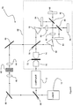
- FIG. 6 illustrates a CARS system 54 that is a variant of CARS system 10 of Figure 1 .
- a beam splitter 56 diverts part of the output of the laser 14 away from the chirp unit 12 to form a beam that is reflected from a mirror 58 and then focussed by a lens 60 into a small volume within non-linear element 62 such as a sapphire plate or a high refractive index liquid.
- Light emerging from the focal volume within the non-linear element 62 results from a third-order mixing process within the non-linear element 62 (e.g. the optical Kerr effect).
- Light emerging from the focal volume within the non-linear element 62 is then focussed back into a beam by lens 64.
- the beam from lens 64 is then reflected from mirror 66 and into microscope 68 as a reference beam.
- the microscope 68 includes an objective lens 70 for focussing the Stokes and pump pulses from the chirp unit 12 into a volume within the sample 72.
- a further objective lens 74 collects CARS pulse light from the targeted volume within the sample 72 and projects it as a beam onto a beam splitter 76. Also incident upon beam splitter 76 is the reference beam from the non-linear element 62.
- Some (ideally half) of the light from the objective lens 74 is transmitted through the beam splitter 76 to a prism 78 and some of the light from the reference beam is reflected from the beam splitter 76 to the prism 78.
- the beam emerging from the prism 78 is focussed by a lens 80 and is divided into two orthogonally polarised components by polarising beam splitter 82.
- the polarised components are then detected by respective line scan cameras 84 and 86 lying in the image plane of the lens 80.
- the prism 78 creates a wavelength dispersion in the light received from the beam splitter 76 and the lens 80 translates the wavelength dispersion into a range of positions along each of the line scan cameras 84 and 86.
- Some (ideally half) of the light from objective lens 74 is reflected by the beam splitter 76 to a prism 88 and some of the light from the reference beam is transmitted through the beam splitter 76 to the prism 88.
- the beam emerging from the prism 88 is focussed by a lens 90 and is divided into two orthogonally polarised components by polarising beam splitter 92.
- the polarised components are then detected by respective line scan cameras 94 and 96 lying in the image plane of the lens 90.
- the prism 88 creates a wavelength dispersion in the light received from the beam splitter 76 and the lens 90 translates the wavelength dispersion into a range of positions along each of the line scan cameras 94 and 96.
- the polarised components travelling to line scan cameras 86 and 96 have parallel polarisations.
- the interference between CARS light and reference beam creates a spectral intensity interference pattern on each line scan camera 84, 86 94 and 96.
- the images from a pair of cameras receiving the same polarisation e.g. cameras 84 and 94
- the spectral amplitude and phase of the CARS light can be retrieved by spectral interferometry ( J. Opt.
- the glass blocks 24, 28 and 30 are redesigned such that, although both the Stokes and pump beams are still given linear chirps, the rate of change of frequency of a Stokes beam pulse is now very different to the rate of change of frequency of a pump beam pulse.
- the Stokes beam pulses are chirped only slightly, in order to reduce the peak power applied to the sample material.
- the pump beam pulses are strongly chirped such that the frequencies in a pump beam pulse arrive at the sample over a relatively long period of time, comparable to the vibrational dephasing times. The effect of these changes to the chirp unit 12 is illustrated in Figure 7 .
- that diagram illustrates the option of redesigning the dichroic beam splitter 18 to use a smaller frequency sub-band for the pump beam than previously.
- This sub-band is located at the upper end of the band of output frequencies of the laser 14 such that a relatively large central sub-band of the band of output frequencies of the laser 14 is not used to illuminate the sample in the microscope 16. This reduces the power to which the sample material is exposed and therefore reduces the risk of damaging the sample material.
- Figure 7 shows in graph 98 the sub-bands of the output band of the laser 14 that are now used for the Stokes and pump beams.
- the dashed line represents, as in Figure 3 , the band of output frequencies of the laser 14.
- the adjusted sub-band that is allocated to the pump beam is indicated 99. It will be apparent that the gap between sub-band 99 and the sub-band 36 that is used for the Stokes beam is now wider than the gap between sub-bands 38 and 36 in Figure 3 , representing a reduction in the power that is applied to the sample achieved through the optional redesign of the dichroic beam splitter 18.
- Figure 7 also provides a graph 100 illustrating the modified forms now taken by a Stokes pulse 102 and a pump pulse 104 derived from the same pulse from the laser 14.
- CARS light produced in response to pulses 102 and 104 consists of a collection of CARS pulses 106 to 110 that each relate to a different resonant frequency of the sample material.
- Each of the CARS pulses 106 to 110 endures for a period of time determined by the coherence time of its vibrational mode. The vibrational coherence time decreases from pulse 106 to pulse 108 to pulse 110.
- the CARS light gathered by objective 74 in response to Stokes pulse 102 and pump pulse 104 is shown again in graph 112 in Figure 8 .
- the microscope 68 detects the CARS light in terms of its amplitude and phase
- mathematical techniques such as those described in OPTICS LETTERS 31, 1543 (2006 ) can be applied to mathematical data representing the CARS light detected by the microscope 68 in order to flatten the slopes of pulses 106 to 110 that are due to the chirping of the pump pulse 104.
- This recovers a spectrum as shown in graph 114 in which the different vibrational modes that have been excited within the sample can be distinguished: pulses 106 to 110 have been flattened into pulses 116 to 120, respectively.
- the spectral of the temporal CARS response can be retrieved in amplitude and phase, which can be used to retrieve the chemical composition by linear decomposition, as opposed to measuring the CARS intensity only.
- CARS system 122 is shown in Figure 9 .
- CARS system 122 is a variant of CARS system 10 in which a pulse replicating unit 124 has been inserted between the laser 14 and the chirp unit 12.
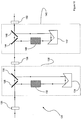
- the pulse replicating unit 124 is shown in greater detail in Figure 10 .
- the beam from the laser 14 enters the pulse replicating unit 124 and passes through a half wave plate 126.
- the laser beam then proceeds to a polarising beam splitter 128 which splits the laser beam into orthogonally polarised components.
- One of these components is a "transmitted component” that is transmitted through the polarising beam splitter 128 to a second polarising beam splitter 130.
- the other component is a "reflected component” that is reflected through a dispersive glass block 132 and is then reflected by a mirror pair 134 to the second polarising beam splitter 130.
- the half-wave plate 126 is orientated to rotate the linear polarization of the input laser beam to give desired relative intensities to the transmitted and reflected components produced by the polarizing beam splitter 128.
- the second polarising beam splitter is orientated to transmit the transmitted component and to reflect the reflected component to travel in the same direction.
- the recombined polarisations of the laser beam then travel from the polarising beam splitter 130 to a half wave plate 136.
- the polarising beam splitters 128 and 130, the glass block 132 and the mirror pair 134 constitute a first delay arm 138 that delays the reflected component of the laser beam by an amount T 1 relative to the transmitted component of the laser beam.
- the reflected component undergoes dispersion in the delay arm 138 by an extent determined by the properties of the glass block 132, and the effects of this dispersion will be described later.
- the laser beam proceeds through a further delay arm 140 having a construction analogous to that of arm 138.
- the half wave plate 136 is orientated to give desired relative intensities to the orthogonally polarised components produced by polarising beam splitter 144.
- Delay arm 140 imposes a delay of T 2 on the component of the laser beam that travels to mirror pair 142 relative to the component that travels straight through polarising beam splitters 144 and 146.
- the component of the laser beam that travels through glass block 148 undergoes additional dispersion.
- the laser beam travels through a quarter wave plate 150 and then into the chirping unit 12.
- Figures 11a to 11h show the effect of the pulse replicating unit 124 on an arbitrary pulse from the laser 14.
- Each of Figures 11a to 11h provides a pair of graphs of intensity versus time.
- the upper graph in each pair shows intensity in the polarisation parallel to that of the reflected component produced by polarising beam splitter 128 and the lower graph in each pair shows intensity in the orthogonal polarisation parallel to the transmitted component of polarising beam splitter 128.
- the two orthogonal polarisations shown in Figures 11a to 11h shall henceforth be referred to as the "reference polarisations".
- the time axes of the upper and lower graphs are aligned to some common zero time.
- the polarisations of the transmitted components of polarising beam splitters 128 and 144 are parallel and that the polarisations of the reflected components produced by polarising beam splitters 128 and 144 are parallel.
- Figure 11a shows the output of the half wave plate 126 in response to an arbitrary pulse from the laser 14.
- the half wave plate 126 is positioned to rotate the linear polarisation of the arriving laser pulse so that its intensity is split equally between the reference polarisations giving orthogonally polarised pulses 151 and 153.
- Figure 11b shows the output of polarising beam splitter 128 towards block 132, i.e. just pulse 151.
- Figure 11c shows the output of polarising beam splitter 128 towards splitter 130, i.e. just pulse 153.
- Figure 11d shows the output of polarising beam splitter 130, i.e. pulse 153 and, a time T 1 later, pulse 151.
- the light from polarising beam splitter 130 travels towards half wave plate 136.
- the half wave plate 136 is angled so as to divide pulse 153 equally between the reference polarisations to create pulses 152 and 154, as shown in Figure 11e .
- delayed pulse 151 is divided equally into pulses 158 and 156, again as shown in Figure 11e.
- Figure 11f shows the output of polarising beam splitter 144 towards block 148, i.e. just pulses 154 and 158.
- Figure 11g shows the output of polarising beam splitter 144 towards splitter 146, i.e. just pulses 152 and 156.
- Figure 11h shows the output of polarising beam splitter 146, i.e.
- the delays T 1 and T 2 are constrained such that all four pulses fall within a pulse repetition period T REP of the laser 14 (1/T REP being the rate at which the laser emits pulses).
- the quarter wave plate 150 converts the linear polarisations of pulses 152 to 158 into circular polarisations so that, when pulses 152 to 158 are applied to a sample, the CARS response that they elicit, when time-averaged, is independent of the specific orientation between the polarisation of the pulses and the structure of the sample.
- Figure 12 shows not only the effect of that dispersion but also the effect of dichroic beam splitter 18 in the chirp unit 12 on the pulses 152 to 158. Accordingly, Figure 12 shows pulse 152 split by the dichroic beam splitter 18 into a Stokes pulse 152a and a pump pulse 152b. Likewise, pulses 154 to 158 are split into respective Stokes pulses 154a to 158a and respective pump pulses 154b to 158b.
- Pulse 154 has been dispersed by glass block 148 and therefore "leans forward" in Figure 12 , as indicated by the dashed line connecting pulses 154a and 154b.
- the onset of the pump pulse 154b is delayed slightly with respect to the onset of the Stokes pulse 154a. This delay alters the size of parameter ⁇ (see Figure 5 and the corresponding description) and hence the IFD that pulses 154a and b would otherwise target according to the current position of adjustable retroreflector 32 and the dispersion introduced by glass blocks 24, 28 and 30.
- the delay between the start of Stokes pulse 154a and the start of pump pulse 154b adjusts the resonant frequency ⁇ v , that pulse 154 targets.
- the start of pump pulse 156b is delayed with respect to the start of Stokes pulse 156a by the dispersion of glass block 132 and the start of pump pulse 158b is delayed with respect to the start of Stokes pulse 158a by the dispersion of glass blocks 132 and 148. Accordingly, all four pulses 152 to 158, due to their differing degrees of dispersion, target different resonant frequencies in the sample.
- the chirping of the pulses 152a to 158b by the glass blocks 24, 28 and 30 and the delaying effect of the path difference in the routes to mirrors 26 and 32 is not illustrated in Figure 12 in order to avoid complicating the diagram.
- the repetition period T REP of the pulses from the laser 14 is again shown in Figure 12 .
- the microscope 16 detects CARS pulses from the sample using a photomultiplier which transduces the intensity of the received CARS light into an electrical signal, I(t).
- I(t) an electrical signal
- Each of 152 to 158 can produce a corresponding pulse of CARS light and these CARS pulses are short compared to the time resolution of this photomultiplier such that the CARS pulses can be considered instantaneous in the electrical signal I(t) Therefore, ignoring noise and the like, the signal I(t) has the form of a series of delta functions that repeats every T REP .
- the magnitudes A 1 , A 2 , A 3 and A 4 of the four CARS pulses 152 to 158 can be recovered.
- Figure 13 shows an electrical circuit 160 within the microscope 16 for processing the photomultiplier signal I(t) to deduce a 0 2 , , a 1 , b 1 and a 2 .
- the signal I(t) from the photomultiplier is applied on input line 162.
- Input line 164 receives an electrical signal that is derived from a photodiode (not shown) within the laser 14 and which consists of a delta function repeated at the pulsing frequency of the laser 14 (limited by the bandwidth of the photodiode which , just to clarify, is typically about 500MHz, i.e. 8 ⁇ 1 ).
- the electrical signal applied to line 164 is therefore also a Fourier series of the same frequencies that are contained in I(t).
- the circuit 160 also contains a number of low pass filters 174 to 188. Filters 174 to 180 block frequencies above ⁇ 1 2 , filters 182 and 184 block frequencies above 3 ⁇ 1 2 and filters 186 and 188 block frequencies above 5 ⁇ 1 2 .
- the circuit also includes a delay line 190 for delaying the signal exiting filter 182 by T REP 4 to phase shift that signal by ⁇ 2 radians.
- the circuit 160 also includes a number of mixers 192 to 196, each arranged to perform frequency down conversion.
- the signals supplied to the circuit 160 contain only frequencies that satisfy the relation k ⁇ 1 , where k is an integer (including zero). Therefore, the output of mixer 192 contains a d.c. component that is proportional to a 1 , the output of mixer 194 contains a d.c. component that is proportional to b 1 and the output of mixer 196 contains a d.c. component that is proportional to a 2 .
- the proportionality constants for a 1 , b 1 and a 2 are determined by the losses of mixers 192 to 196 and by the amplitude of the signal on line 164.
- Coefficient a 1 is a measure of the difference in size between CARS pulse heights A 1 and A 2 and can therefore be used in a differential measuring technique, as will now be described.
- this CARS pulse will include CARS light from the vibrational mode whose resonant frequency, call it f 0 , is targeted by the IFD to which pulse 152 corresponds.
- the CARS pulse will also include non-resonant CARS light from all the vibrational modes of the material lying within the focal volume of the microscope 16 that have a resonant frequency of greater than f 0 , and also from purely electronic contributions.
- This non-resonant CARS light is a background CARS signal that tends to mask the wanted CARS signal that is the CARS light from the vibrational mode whose resonant frequency is f 0 .
- pulse 152 which, it will be recalled, draws a CARS response of magnitude A 1
- pulse 154 which, it will be recalled, draws a CARS response of magnitude A 2
- the half wave plate 126 is are adjusted to alter the magnitudes of peaks 152 and 156 so that the CARS pulse magnitudes A 1 and A 3 are substantially equal and a 1 (the output signal of filter 176) is substantially zero. In this situation, the CARS pulse magnitudes A 1 and A 2 are due entirely to non-resonant CARS light. Then, the sample material is located within the focal volume. Any change that results in the output signal of filter 176 is thus attributable to resonant CARS light from the vibrational mode of interest that has a resonant frequency of f 1 .
- the nulling of the output signal of filter 176 by adjusting the half wave plate 126 has the effect of compensating the non-resonant CARS background signal from water when the microscope is used to investigate a real sample. Since all four pulses are derived from the same laser pulse, they do not exhibit equal classical intensity fluctuations, which are completely suppressed in the balanced signal a 1 , which can therefore be limited only by the shot-noise of the signal. This enables a sensitive detection of small changes in material composition. A similar argument holds for the coefficients a 2,3 , so that in total three balanced signals are extracted.
- the CARS system 122 can be adapted to perform some other measurements, as will now be explained.
- the beam directions of the four pulses 152 to 158 can all be made slightly different by the tip/tilt of beam splitters 146 and 130 Then, the microscope will focus the pulses into laterally displaced focal volumes within the sample.
- the CARS pulses produced in response to pulses 152 to 158 relate to different locations within the sample.
- the coefficient a 1 represents a spatial gradient in the CARS response within the sample (since A 1 and A 3 now relate to different locations within the sample). Similar arguments hold for a 2.3 .
- the additional half wave plate can of course be rotated to rotate the two orthogonal polarisations of the pulses 152 to 158 relative to the sample material.
Landscapes
- Physics & Mathematics (AREA)
- Spectroscopy & Molecular Physics (AREA)
- General Physics & Mathematics (AREA)
- Health & Medical Sciences (AREA)
- Nuclear Medicine, Radiotherapy & Molecular Imaging (AREA)
- Life Sciences & Earth Sciences (AREA)
- Chemical & Material Sciences (AREA)
- Analytical Chemistry (AREA)
- Biochemistry (AREA)
- General Health & Medical Sciences (AREA)
- Immunology (AREA)
- Pathology (AREA)
- Investigating, Analyzing Materials By Fluorescence Or Luminescence (AREA)
Claims (14)
- Appareil CARS (122) pour étudier un échantillon, l'appareil comprenant :- une source de lumière (14) pour émettre une lumière pulsée ;- des moyens de conversion (124) pour convertir une impulsion de lumière provenant de la source en une pluralité d'impulsions de lumière dérivées réparties dans le temps ;- des moyens de séparation pour séparer chaque impulsion de lumière dérivée en une première impulsion d'interrogation consistant en un sous-ensemble des fréquences de l'impulsions de lumière dérivée et une deuxième impulsion d'interrogation consistant en un sous-ensemble différent de ces fréquences ;- des moyens de modulation en fréquence pour moduler en fréquence les première et deuxième impulsions d'interrogation de chaque impulsion de lumière dérivée ;- des moyens d'application pour appliquer les première et deuxième impulsions d'interrogation modulées en fréquence de chaque impulsion de lumière dérivée à l'échantillon de manière superposée dans le temps ; et- des moyens de détection pour détecter une lumière stimulée qui est stimulée à partir de l'échantillon par l'interaction des première et deuxième impulsions d'interrogation modulées en fréquence de chaque impulsion de lumière dérivée.
- Appareil CARS selon la revendication 1, dans lequel les moyens de modulation en fréquence sont agencés pour moduler en fréquence la première impulsion d'interrogation de chaque impulsion de lumière dérivée en introduisant dans celle-ci une première dispersion sensiblement linéaire sur au moins une bande de fréquences de celle-ci et sont agencés pour moduler en fréquence la deuxième impulsion d'interrogation de chaque impulsion de lumière dérivée en introduisant dans celle-ci une deuxième dispersion sensiblement linéaire sur au moins une bande de fréquences de celle-ci.
- Appareil CARS selon la revendication 2, dans lequel les première et deuxième dispersions linéaires ont sensiblement le même taux de variation de retard avec la fréquence.
- Appareil CARS selon la revendication 3, dans lequel les moyens de détection produisent un signal enregistrant la lumière stimulée détectée dans le temps et l'appareil comprend en outre des moyens de calcul pour calculer au moins une quantité, la ou chaque quantité étant au moins indicative d'un coefficient respectif d'une série de Fourier représentant le signal.
- Appareil CARS selon l'une quelconque des revendications 1 à 4, dans lequel les moyens de conversion comprennent des moyens de division pour diviser l'impulsion provenant de la source en des parties qui se propagent le long de trajets de différentes longueurs pour atteindre l'échantillon.
- Appareil CARS selon l'une quelconque des revendications 1 à 5, comprenant en outre des moyens de déflexion pour créer une différence dans la direction de propagation entre les première et deuxième impulsions de lumière dérivées de sorte que les première et deuxième impulsions d'interrogation modulées en fréquence de la première impulsion de lumière dérivée stimulent la lumière provenant d'un premier emplacement dans l'échantillon et que les première et deuxième impulsions d'interrogation modulées en fréquence de la deuxième impulsion de lumière dérivée stimulent la lumière provenant d'un emplacement différent dans l'échantillon.
- Appareil CARS selon l'une quelconque des revendications 1 à 6, dans lequel les moyens d'application comprennent des moyens d'ajustement pour appliquer un ajustement commun à la période entre les arrivées au niveau de l'échantillon des débuts des première et deuxième impulsions d'interrogation modulées en fréquence, pour la totalité desdites impulsions de lumière dérivées.
- Appareil CARS selon l'une quelconque des revendications précédentes, dans lequel les moyens de modulation en fréquence comprennent un verre dispersif dans les trajets parcourus par les première et deuxième impulsions d'interrogation.
- Appareil CARS selon l'une quelconque des revendications précédentes, dans lequel les moyens de détection sont agencés pour détecter la lumière stimulée à partir de l'échantillon en termes de son amplitude et de sa phase.
- Appareil CARS selon la revendication 9, dans lequel les moyens de détection comprennent en outre des moyens de traitement agencés pour dériver, d'un enregistrement de la lumière stimulée à partir de l'échantillon en termes de son amplitude et de sa phase, un spectre de la lumière stimulée à partir de l'échantillon.
- Appareil CARS selon l'une quelconque des revendications précédentes, dans lequel la source de lumière comprend un laser large bande pulsé.
- Appareil CARS selon l'une quelconque des revendications précédentes, dans lequel les moyens de détection comprennent des moyens de discrimination pour discriminer la lumière CARS dans ladite lumière qui est stimulée à partir de l'échantillon.
- Appareil CARS selon l'une quelconque des revendications précédentes, dans lequel les moyens de détection sont agencés pour discriminer la lumière stimulée à partir de l'échantillon dans une polarisation linéaire donnée.
- Procédé CARS d'étude d'un échantillon, le procédé comprenant :- la fourniture d'une lumière pulsée provenant d'une source ;- la conversion d'une impulsion de lumière provenant de la source en une pluralité d'impulsions de lumière dérivées réparties dans le temps ;- la séparation de chaque impulsion de lumière dérivée en une première impulsion d'interrogation consistant en un sous-ensemble des fréquences de l'impulsion de lumière dérivée et une deuxième impulsion d'interrogation consistant en un sous-ensemble différent de ces fréquences ;- la modulation en fréquence des première et deuxième impulsions d'interrogation de chaque impulsion de lumière dérivée ;- l'application des première et deuxième impulsions d'interrogation modulées en fréquence de chaque impulsion de lumière dérivée à l'échantillon d'une manière superposée dans le temps ; et- la détection de la lumière stimulée qui est stimulée à partir de l'échantillon par l'interaction des première et deuxième impulsions d'interrogation modulées en fréquence de chaque impulsion de lumière dérivée.
Applications Claiming Priority (2)
| Application Number | Priority Date | Filing Date | Title |
|---|---|---|---|
| GB0904739A GB0904739D0 (en) | 2009-03-19 | 2009-03-19 | Coherent anti-stokes raman spectroscopy |
| PCT/GB2010/050473 WO2010106376A1 (fr) | 2009-03-19 | 2010-03-19 | Spectroscopie raman anti-stokes cohérente |
Publications (2)
| Publication Number | Publication Date |
|---|---|
| EP2409140A1 EP2409140A1 (fr) | 2012-01-25 |
| EP2409140B1 true EP2409140B1 (fr) | 2016-05-04 |
Family
ID=40639817
Family Applications (1)
| Application Number | Title | Priority Date | Filing Date |
|---|---|---|---|
| EP10711255.9A Not-in-force EP2409140B1 (fr) | 2009-03-19 | 2010-03-19 | Diffusion raman anti-stokes coherente |
Country Status (5)
| Country | Link |
|---|---|
| US (1) | US9128059B2 (fr) |
| EP (1) | EP2409140B1 (fr) |
| JP (1) | JP5705825B2 (fr) |
| GB (1) | GB0904739D0 (fr) |
| WO (1) | WO2010106376A1 (fr) |
Families Citing this family (9)
| Publication number | Priority date | Publication date | Assignee | Title |
|---|---|---|---|---|
| JP5736325B2 (ja) * | 2012-02-21 | 2015-06-17 | 株式会社日立製作所 | 光学装置 |
| DE102013112750B4 (de) * | 2013-11-19 | 2016-03-31 | Leica Microsystems Cms Gmbh | Einrichtung und Verfahren zum Beleuchten einer Probe |
| JP6324709B2 (ja) * | 2013-11-27 | 2018-05-16 | 株式会社日立ハイテクノロジーズ | 光計測装置及び光計測方法 |
| US10866189B2 (en) | 2015-11-24 | 2020-12-15 | Hitachi, Ltd. | Optical measurement apparatus and optical measurement method |
| FR3048503A1 (fr) | 2016-03-01 | 2017-09-08 | Centre Nat Rech Scient | Dispositif optique d'excitation pour generer des processus raman stimules, ensemble de mesure de processus raman stimules et procede d'excitation optique pour generer des processus raman stimules |
| CN113631897B (zh) * | 2019-04-29 | 2024-07-16 | Atonarp株式会社 | 混合光学系统 |
| CN110646402B (zh) * | 2019-10-16 | 2021-11-02 | 华东师范大学重庆研究院 | 一种超分辨快速扫描的相干拉曼散射成像方法 |
| WO2022093750A1 (fr) * | 2020-10-30 | 2022-05-05 | Arizona Board Of Regents On Behalf Of The University Of Arizona | Double peigne à cavité unique à fibre unique pour spectroscopie de diffusion raman anti-stokes cohérente fondée sur la focalisation spectrale |
| EP4413355A1 (fr) * | 2021-10-06 | 2024-08-14 | Atonarp Inc. | Procédé et système d'acquisition de spectre de cars |
Family Cites Families (8)
| Publication number | Priority date | Publication date | Assignee | Title |
|---|---|---|---|---|
| JP4854878B2 (ja) * | 2001-07-03 | 2012-01-18 | オリンパス株式会社 | レーザー顕微鏡 |
| US7256885B2 (en) | 2003-01-29 | 2007-08-14 | Yeda Research And Development Company Ltd. | Coherently controlled nonlinear Raman spectroscopy and microscopy |
| ATE514060T1 (de) | 2004-05-27 | 2011-07-15 | Yeda Res & Dev | Kohärent gesteuerte nichtlineare raman- spektroskopie |
| US7586618B2 (en) * | 2005-02-28 | 2009-09-08 | The Board Of Trustees Of The University Of Illinois | Distinguishing non-resonant four-wave-mixing noise in coherent stokes and anti-stokes Raman scattering |
| US7542137B2 (en) * | 2006-07-24 | 2009-06-02 | University Of Ottawa | Pathogen detection using coherent anti-stokes Raman scattering microscopy |
| US7847933B2 (en) | 2007-05-22 | 2010-12-07 | Stevens Institute Of Technology | Cars microscopy and spectroscopy using ultrafast chirped pulses |
| JP5160372B2 (ja) * | 2008-10-17 | 2013-03-13 | オリンパス株式会社 | レーザ顕微鏡装置 |
| US8610996B2 (en) * | 2010-05-06 | 2013-12-17 | Leica Microsystems Cms Gmbh | Tunable multiple laser pulse scanning microscope and method of operating the same |
-
2009
- 2009-03-19 GB GB0904739A patent/GB0904739D0/en not_active Ceased
-
2010
- 2010-03-19 US US13/257,194 patent/US9128059B2/en not_active Expired - Fee Related
- 2010-03-19 WO PCT/GB2010/050473 patent/WO2010106376A1/fr not_active Ceased
- 2010-03-19 EP EP10711255.9A patent/EP2409140B1/fr not_active Not-in-force
- 2010-03-19 JP JP2012500322A patent/JP5705825B2/ja not_active Expired - Fee Related
Also Published As
| Publication number | Publication date |
|---|---|
| WO2010106376A1 (fr) | 2010-09-23 |
| GB0904739D0 (en) | 2009-05-06 |
| JP5705825B2 (ja) | 2015-04-22 |
| JP2012521001A (ja) | 2012-09-10 |
| US9128059B2 (en) | 2015-09-08 |
| US20120092662A1 (en) | 2012-04-19 |
| EP2409140A1 (fr) | 2012-01-25 |
Similar Documents
| Publication | Publication Date | Title |
|---|---|---|
| EP2409140B1 (fr) | Diffusion raman anti-stokes coherente | |
| US6865014B2 (en) | Apparatus and method for investigating a sample | |
| EP1754033B1 (fr) | Spectroscopie raman non lineaire controlee de façon coherente | |
| EP2211430A2 (fr) | Système d'autocorrélation laser | |
| EP3796068B1 (fr) | Dispositif de génération de paire d'impulsions optiques, dispositif de détection de lumière et procédé de détection de lumière | |
| JP4862164B2 (ja) | パルスレーザ光のタイミング調整装置、調整方法及び光学顕微鏡 | |
| EP2601514B1 (fr) | Procédé et appareil de réduction de fond non résonant dans la spectroscopie par diffusion raman anti-stokes cohérente (cars) | |
| CN110579462B (zh) | 一种基于高重频飞秒激光的时间分辨宽谱cars光谱成像装置 | |
| US11874227B2 (en) | Method and apparatus for terahertz or microwave imaging | |
| US20150204790A1 (en) | Stimulated raman scattering measurement apparatus | |
| US11041760B2 (en) | Optical measurement device and optical measurement method | |
| US11181423B2 (en) | Birefringent interferometer for measuring photoluminescence properties of samples | |
| US6204926B1 (en) | Methods and system for optically correlating ultrashort optical waveforms | |
| JP5508899B2 (ja) | レーザ顕微鏡装置 | |
| KR20160044344A (ko) | 2차원 분광 시스템 및 분석 방법 | |
| US12523611B2 (en) | Method and system for acquiring cars spectrum | |
| US10132754B2 (en) | Device and method for illuminating a sample | |
| US7515262B2 (en) | Crystal grating apparatus | |
| JP2000214082A (ja) | 媒質の非線形光学応答測定装置 | |
| WO2019167478A1 (fr) | Procédé et dispositif de mesure spectroscopique bidimensionnelle | |
| JP2003121334A (ja) | 高分解能顕微鏡、及び位相緩和時間測定法 |
Legal Events
| Date | Code | Title | Description |
|---|---|---|---|
| PUAI | Public reference made under article 153(3) epc to a published international application that has entered the european phase |
Free format text: ORIGINAL CODE: 0009012 |
|
| 17P | Request for examination filed |
Effective date: 20110914 |
|
| AK | Designated contracting states |
Kind code of ref document: A1 Designated state(s): AT BE BG CH CY CZ DE DK EE ES FI FR GB GR HR HU IE IS IT LI LT LU LV MC MK MT NL NO PL PT RO SE SI SK SM TR |
|
| DAX | Request for extension of the european patent (deleted) | ||
| 17Q | First examination report despatched |
Effective date: 20130322 |
|
| GRAP | Despatch of communication of intention to grant a patent |
Free format text: ORIGINAL CODE: EPIDOSNIGR1 |
|
| RIC1 | Information provided on ipc code assigned before grant |
Ipc: G01J 3/44 20060101ALI20151026BHEP Ipc: G01J 3/02 20060101ALI20151026BHEP Ipc: G01N 21/65 20060101AFI20151026BHEP |
|
| INTG | Intention to grant announced |
Effective date: 20151117 |
|
| RAP1 | Party data changed (applicant data changed or rights of an application transferred) |
Owner name: UNIVERSITY COLLEGE CARDIFF CONSULTANTS LTD |
|
| GRAS | Grant fee paid |
Free format text: ORIGINAL CODE: EPIDOSNIGR3 |
|
| GRAA | (expected) grant |
Free format text: ORIGINAL CODE: 0009210 |
|
| AK | Designated contracting states |
Kind code of ref document: B1 Designated state(s): AT BE BG CH CY CZ DE DK EE ES FI FR GB GR HR HU IE IS IT LI LT LU LV MC MK MT NL NO PL PT RO SE SI SK SM TR |
|
| REG | Reference to a national code |
Ref country code: GB Ref legal event code: FG4D |
|
| REG | Reference to a national code |
Ref country code: CH Ref legal event code: EP |
|
| REG | Reference to a national code |
Ref country code: AT Ref legal event code: REF Ref document number: 797352 Country of ref document: AT Kind code of ref document: T Effective date: 20160515 |
|
| REG | Reference to a national code |
Ref country code: IE Ref legal event code: FG4D |
|
| REG | Reference to a national code |
Ref country code: DE Ref legal event code: R096 Ref document number: 602010033028 Country of ref document: DE |
|
| REG | Reference to a national code |
Ref country code: NL Ref legal event code: MP Effective date: 20160504 |
|
| REG | Reference to a national code |
Ref country code: LT Ref legal event code: MG4D |
|
| PG25 | Lapsed in a contracting state [announced via postgrant information from national office to epo] |
Ref country code: LT Free format text: LAPSE BECAUSE OF FAILURE TO SUBMIT A TRANSLATION OF THE DESCRIPTION OR TO PAY THE FEE WITHIN THE PRESCRIBED TIME-LIMIT Effective date: 20160504 Ref country code: NL Free format text: LAPSE BECAUSE OF FAILURE TO SUBMIT A TRANSLATION OF THE DESCRIPTION OR TO PAY THE FEE WITHIN THE PRESCRIBED TIME-LIMIT Effective date: 20160504 Ref country code: NO Free format text: LAPSE BECAUSE OF FAILURE TO SUBMIT A TRANSLATION OF THE DESCRIPTION OR TO PAY THE FEE WITHIN THE PRESCRIBED TIME-LIMIT Effective date: 20160804 Ref country code: FI Free format text: LAPSE BECAUSE OF FAILURE TO SUBMIT A TRANSLATION OF THE DESCRIPTION OR TO PAY THE FEE WITHIN THE PRESCRIBED TIME-LIMIT Effective date: 20160504 |
|
| REG | Reference to a national code |
Ref country code: AT Ref legal event code: MK05 Ref document number: 797352 Country of ref document: AT Kind code of ref document: T Effective date: 20160504 |
|
| PG25 | Lapsed in a contracting state [announced via postgrant information from national office to epo] |
Ref country code: PT Free format text: LAPSE BECAUSE OF FAILURE TO SUBMIT A TRANSLATION OF THE DESCRIPTION OR TO PAY THE FEE WITHIN THE PRESCRIBED TIME-LIMIT Effective date: 20160905 Ref country code: SE Free format text: LAPSE BECAUSE OF FAILURE TO SUBMIT A TRANSLATION OF THE DESCRIPTION OR TO PAY THE FEE WITHIN THE PRESCRIBED TIME-LIMIT Effective date: 20160504 Ref country code: ES Free format text: LAPSE BECAUSE OF FAILURE TO SUBMIT A TRANSLATION OF THE DESCRIPTION OR TO PAY THE FEE WITHIN THE PRESCRIBED TIME-LIMIT Effective date: 20160504 Ref country code: HR Free format text: LAPSE BECAUSE OF FAILURE TO SUBMIT A TRANSLATION OF THE DESCRIPTION OR TO PAY THE FEE WITHIN THE PRESCRIBED TIME-LIMIT Effective date: 20160504 Ref country code: LV Free format text: LAPSE BECAUSE OF FAILURE TO SUBMIT A TRANSLATION OF THE DESCRIPTION OR TO PAY THE FEE WITHIN THE PRESCRIBED TIME-LIMIT Effective date: 20160504 Ref country code: GR Free format text: LAPSE BECAUSE OF FAILURE TO SUBMIT A TRANSLATION OF THE DESCRIPTION OR TO PAY THE FEE WITHIN THE PRESCRIBED TIME-LIMIT Effective date: 20160805 |
|
| PG25 | Lapsed in a contracting state [announced via postgrant information from national office to epo] |
Ref country code: IT Free format text: LAPSE BECAUSE OF FAILURE TO SUBMIT A TRANSLATION OF THE DESCRIPTION OR TO PAY THE FEE WITHIN THE PRESCRIBED TIME-LIMIT Effective date: 20160504 |
|
| PG25 | Lapsed in a contracting state [announced via postgrant information from national office to epo] |
Ref country code: RO Free format text: LAPSE BECAUSE OF FAILURE TO SUBMIT A TRANSLATION OF THE DESCRIPTION OR TO PAY THE FEE WITHIN THE PRESCRIBED TIME-LIMIT Effective date: 20160504 Ref country code: DK Free format text: LAPSE BECAUSE OF FAILURE TO SUBMIT A TRANSLATION OF THE DESCRIPTION OR TO PAY THE FEE WITHIN THE PRESCRIBED TIME-LIMIT Effective date: 20160504 Ref country code: CZ Free format text: LAPSE BECAUSE OF FAILURE TO SUBMIT A TRANSLATION OF THE DESCRIPTION OR TO PAY THE FEE WITHIN THE PRESCRIBED TIME-LIMIT Effective date: 20160504 Ref country code: SK Free format text: LAPSE BECAUSE OF FAILURE TO SUBMIT A TRANSLATION OF THE DESCRIPTION OR TO PAY THE FEE WITHIN THE PRESCRIBED TIME-LIMIT Effective date: 20160504 Ref country code: EE Free format text: LAPSE BECAUSE OF FAILURE TO SUBMIT A TRANSLATION OF THE DESCRIPTION OR TO PAY THE FEE WITHIN THE PRESCRIBED TIME-LIMIT Effective date: 20160504 |
|
| REG | Reference to a national code |
Ref country code: DE Ref legal event code: R097 Ref document number: 602010033028 Country of ref document: DE |
|
| PG25 | Lapsed in a contracting state [announced via postgrant information from national office to epo] |
Ref country code: AT Free format text: LAPSE BECAUSE OF FAILURE TO SUBMIT A TRANSLATION OF THE DESCRIPTION OR TO PAY THE FEE WITHIN THE PRESCRIBED TIME-LIMIT Effective date: 20160504 Ref country code: PL Free format text: LAPSE BECAUSE OF FAILURE TO SUBMIT A TRANSLATION OF THE DESCRIPTION OR TO PAY THE FEE WITHIN THE PRESCRIBED TIME-LIMIT Effective date: 20160504 Ref country code: BE Free format text: LAPSE BECAUSE OF FAILURE TO SUBMIT A TRANSLATION OF THE DESCRIPTION OR TO PAY THE FEE WITHIN THE PRESCRIBED TIME-LIMIT Effective date: 20160504 Ref country code: SM Free format text: LAPSE BECAUSE OF FAILURE TO SUBMIT A TRANSLATION OF THE DESCRIPTION OR TO PAY THE FEE WITHIN THE PRESCRIBED TIME-LIMIT Effective date: 20160504 |
|
| PLBE | No opposition filed within time limit |
Free format text: ORIGINAL CODE: 0009261 |
|
| STAA | Information on the status of an ep patent application or granted ep patent |
Free format text: STATUS: NO OPPOSITION FILED WITHIN TIME LIMIT |
|
| REG | Reference to a national code |
Ref country code: FR Ref legal event code: PLFP Year of fee payment: 8 |
|
| 26N | No opposition filed |
Effective date: 20170207 |
|
| PG25 | Lapsed in a contracting state [announced via postgrant information from national office to epo] |
Ref country code: SI Free format text: LAPSE BECAUSE OF FAILURE TO SUBMIT A TRANSLATION OF THE DESCRIPTION OR TO PAY THE FEE WITHIN THE PRESCRIBED TIME-LIMIT Effective date: 20160504 |
|
| REG | Reference to a national code |
Ref country code: CH Ref legal event code: PL |
|
| PG25 | Lapsed in a contracting state [announced via postgrant information from national office to epo] |
Ref country code: MC Free format text: LAPSE BECAUSE OF FAILURE TO SUBMIT A TRANSLATION OF THE DESCRIPTION OR TO PAY THE FEE WITHIN THE PRESCRIBED TIME-LIMIT Effective date: 20160504 |
|
| REG | Reference to a national code |
Ref country code: IE Ref legal event code: MM4A |
|
| PG25 | Lapsed in a contracting state [announced via postgrant information from national office to epo] |
Ref country code: LU Free format text: LAPSE BECAUSE OF NON-PAYMENT OF DUE FEES Effective date: 20170319 |
|
| PG25 | Lapsed in a contracting state [announced via postgrant information from national office to epo] |
Ref country code: LI Free format text: LAPSE BECAUSE OF NON-PAYMENT OF DUE FEES Effective date: 20170331 Ref country code: CH Free format text: LAPSE BECAUSE OF NON-PAYMENT OF DUE FEES Effective date: 20170331 Ref country code: IE Free format text: LAPSE BECAUSE OF NON-PAYMENT OF DUE FEES Effective date: 20170319 |
|
| REG | Reference to a national code |
Ref country code: FR Ref legal event code: PLFP Year of fee payment: 9 |
|
| PGFP | Annual fee paid to national office [announced via postgrant information from national office to epo] |
Ref country code: DE Payment date: 20180309 Year of fee payment: 9 Ref country code: GB Payment date: 20180201 Year of fee payment: 9 |
|
| PGFP | Annual fee paid to national office [announced via postgrant information from national office to epo] |
Ref country code: FR Payment date: 20180327 Year of fee payment: 9 |
|
| PG25 | Lapsed in a contracting state [announced via postgrant information from national office to epo] |
Ref country code: MT Free format text: LAPSE BECAUSE OF NON-PAYMENT OF DUE FEES Effective date: 20170319 |
|
| PG25 | Lapsed in a contracting state [announced via postgrant information from national office to epo] |
Ref country code: HU Free format text: LAPSE BECAUSE OF FAILURE TO SUBMIT A TRANSLATION OF THE DESCRIPTION OR TO PAY THE FEE WITHIN THE PRESCRIBED TIME-LIMIT; INVALID AB INITIO Effective date: 20100319 |
|
| PG25 | Lapsed in a contracting state [announced via postgrant information from national office to epo] |
Ref country code: BG Free format text: LAPSE BECAUSE OF FAILURE TO SUBMIT A TRANSLATION OF THE DESCRIPTION OR TO PAY THE FEE WITHIN THE PRESCRIBED TIME-LIMIT Effective date: 20160504 |
|
| REG | Reference to a national code |
Ref country code: DE Ref legal event code: R119 Ref document number: 602010033028 Country of ref document: DE |
|
| PG25 | Lapsed in a contracting state [announced via postgrant information from national office to epo] |
Ref country code: CY Free format text: LAPSE BECAUSE OF NON-PAYMENT OF DUE FEES Effective date: 20160504 |
|
| GBPC | Gb: european patent ceased through non-payment of renewal fee |
Effective date: 20190319 |
|
| PG25 | Lapsed in a contracting state [announced via postgrant information from national office to epo] |
Ref country code: MK Free format text: LAPSE BECAUSE OF FAILURE TO SUBMIT A TRANSLATION OF THE DESCRIPTION OR TO PAY THE FEE WITHIN THE PRESCRIBED TIME-LIMIT Effective date: 20160504 |
|
| PG25 | Lapsed in a contracting state [announced via postgrant information from national office to epo] |
Ref country code: DE Free format text: LAPSE BECAUSE OF NON-PAYMENT OF DUE FEES Effective date: 20191001 Ref country code: GB Free format text: LAPSE BECAUSE OF NON-PAYMENT OF DUE FEES Effective date: 20190319 |
|
| PG25 | Lapsed in a contracting state [announced via postgrant information from national office to epo] |
Ref country code: FR Free format text: LAPSE BECAUSE OF NON-PAYMENT OF DUE FEES Effective date: 20190331 |
|
| PG25 | Lapsed in a contracting state [announced via postgrant information from national office to epo] |
Ref country code: TR Free format text: LAPSE BECAUSE OF FAILURE TO SUBMIT A TRANSLATION OF THE DESCRIPTION OR TO PAY THE FEE WITHIN THE PRESCRIBED TIME-LIMIT Effective date: 20160504 |
|
| PG25 | Lapsed in a contracting state [announced via postgrant information from national office to epo] |
Ref country code: IS Free format text: LAPSE BECAUSE OF FAILURE TO SUBMIT A TRANSLATION OF THE DESCRIPTION OR TO PAY THE FEE WITHIN THE PRESCRIBED TIME-LIMIT Effective date: 20160904 |