EP2409169B1 - Système de cellules électriques doté d'un moyen de détection de discontinuités - Google Patents
Système de cellules électriques doté d'un moyen de détection de discontinuités Download PDFInfo
- Publication number
- EP2409169B1 EP2409169B1 EP10710019.0A EP10710019A EP2409169B1 EP 2409169 B1 EP2409169 B1 EP 2409169B1 EP 10710019 A EP10710019 A EP 10710019A EP 2409169 B1 EP2409169 B1 EP 2409169B1
- Authority
- EP
- European Patent Office
- Prior art keywords
- cell system
- power cell
- voltage
- power
- cells
- Prior art date
- Legal status (The legal status is an assumption and is not a legal conclusion. Google has not performed a legal analysis and makes no representation as to the accuracy of the status listed.)
- Active
Links
Images


Classifications
-
- G—PHYSICS
- G01—MEASURING; TESTING
- G01R—MEASURING ELECTRIC VARIABLES; MEASURING MAGNETIC VARIABLES
- G01R31/00—Arrangements for testing electric properties; Arrangements for locating electric faults; Arrangements for electrical testing characterised by what is being tested not provided for elsewhere
- G01R31/50—Testing of electric apparatus, lines, cables or components for short-circuits, continuity, leakage current or incorrect line connections
- G01R31/52—Testing for short-circuits, leakage current or ground faults
-
- G—PHYSICS
- G01—MEASURING; TESTING
- G01R—MEASURING ELECTRIC VARIABLES; MEASURING MAGNETIC VARIABLES
- G01R31/00—Arrangements for testing electric properties; Arrangements for locating electric faults; Arrangements for electrical testing characterised by what is being tested not provided for elsewhere
- G01R31/36—Arrangements for testing, measuring or monitoring the electrical condition of accumulators or electric batteries, e.g. capacity or state of charge [SoC]
- G01R31/382—Arrangements for monitoring battery or accumulator variables, e.g. SoC
- G01R31/3835—Arrangements for monitoring battery or accumulator variables, e.g. SoC involving only voltage measurements
-
- G—PHYSICS
- G01—MEASURING; TESTING
- G01R—MEASURING ELECTRIC VARIABLES; MEASURING MAGNETIC VARIABLES
- G01R31/00—Arrangements for testing electric properties; Arrangements for locating electric faults; Arrangements for electrical testing characterised by what is being tested not provided for elsewhere
- G01R31/50—Testing of electric apparatus, lines, cables or components for short-circuits, continuity, leakage current or incorrect line connections
- G01R31/54—Testing for continuity
-
- H—ELECTRICITY
- H01—ELECTRIC ELEMENTS
- H01M—PROCESSES OR MEANS, e.g. BATTERIES, FOR THE DIRECT CONVERSION OF CHEMICAL ENERGY INTO ELECTRICAL ENERGY
- H01M10/00—Secondary cells; Manufacture thereof
- H01M10/42—Methods or arrangements for servicing or maintenance of secondary cells or secondary half-cells
- H01M10/425—Structural combination with electronic components, e.g. electronic circuits integrated to the outside of the casing
-
- H—ELECTRICITY
- H01—ELECTRIC ELEMENTS
- H01M—PROCESSES OR MEANS, e.g. BATTERIES, FOR THE DIRECT CONVERSION OF CHEMICAL ENERGY INTO ELECTRICAL ENERGY
- H01M10/00—Secondary cells; Manufacture thereof
- H01M10/42—Methods or arrangements for servicing or maintenance of secondary cells or secondary half-cells
- H01M10/48—Accumulators combined with arrangements for measuring, testing or indicating the condition of cells, e.g. the level or density of the electrolyte
- H01M10/482—Accumulators combined with arrangements for measuring, testing or indicating the condition of cells, e.g. the level or density of the electrolyte for several batteries or cells simultaneously or sequentially
-
- H—ELECTRICITY
- H01—ELECTRIC ELEMENTS
- H01M—PROCESSES OR MEANS, e.g. BATTERIES, FOR THE DIRECT CONVERSION OF CHEMICAL ENERGY INTO ELECTRICAL ENERGY
- H01M8/00—Fuel cells; Manufacture thereof
- H01M8/04—Auxiliary arrangements, e.g. for control of pressure or for circulation of fluids
- H01M8/04298—Processes for controlling fuel cells or fuel cell systems
- H01M8/04313—Processes for controlling fuel cells or fuel cell systems characterised by the detection or assessment of variables; characterised by the detection or assessment of failure or abnormal function
- H01M8/04537—Electric variables
- H01M8/04544—Voltage
- H01M8/04559—Voltage of fuel cell stacks
-
- H—ELECTRICITY
- H01—ELECTRIC ELEMENTS
- H01M—PROCESSES OR MEANS, e.g. BATTERIES, FOR THE DIRECT CONVERSION OF CHEMICAL ENERGY INTO ELECTRICAL ENERGY
- H01M8/00—Fuel cells; Manufacture thereof
- H01M8/04—Auxiliary arrangements, e.g. for control of pressure or for circulation of fluids
- H01M8/04298—Processes for controlling fuel cells or fuel cell systems
- H01M8/04313—Processes for controlling fuel cells or fuel cell systems characterised by the detection or assessment of variables; characterised by the detection or assessment of failure or abnormal function
- H01M8/04664—Failure or abnormal function
- H01M8/04679—Failure or abnormal function of fuel cell stacks
-
- G—PHYSICS
- G01—MEASURING; TESTING
- G01R—MEASURING ELECTRIC VARIABLES; MEASURING MAGNETIC VARIABLES
- G01R31/00—Arrangements for testing electric properties; Arrangements for locating electric faults; Arrangements for electrical testing characterised by what is being tested not provided for elsewhere
- G01R31/28—Testing of electronic circuits, e.g. by signal tracer
- G01R31/282—Testing of electronic circuits specially adapted for particular applications not provided for elsewhere
- G01R31/2829—Testing of circuits in sensor or actuator systems
-
- G—PHYSICS
- G01—MEASURING; TESTING
- G01R—MEASURING ELECTRIC VARIABLES; MEASURING MAGNETIC VARIABLES
- G01R31/00—Arrangements for testing electric properties; Arrangements for locating electric faults; Arrangements for electrical testing characterised by what is being tested not provided for elsewhere
- G01R31/36—Arrangements for testing, measuring or monitoring the electrical condition of accumulators or electric batteries, e.g. capacity or state of charge [SoC]
- G01R31/396—Acquisition or processing of data for testing or for monitoring individual cells or groups of cells within a battery
-
- H—ELECTRICITY
- H01—ELECTRIC ELEMENTS
- H01M—PROCESSES OR MEANS, e.g. BATTERIES, FOR THE DIRECT CONVERSION OF CHEMICAL ENERGY INTO ELECTRICAL ENERGY
- H01M16/00—Structural combinations of different types of electrochemical generators
- H01M16/003—Structural combinations of different types of electrochemical generators of fuel cells with other electrochemical devices, e.g. capacitors, electrolysers
-
- H—ELECTRICITY
- H01—ELECTRIC ELEMENTS
- H01M—PROCESSES OR MEANS, e.g. BATTERIES, FOR THE DIRECT CONVERSION OF CHEMICAL ENERGY INTO ELECTRICAL ENERGY
- H01M8/00—Fuel cells; Manufacture thereof
- H01M8/10—Fuel cells with solid electrolytes
- H01M2008/1095—Fuel cells with polymeric electrolytes
-
- Y—GENERAL TAGGING OF NEW TECHNOLOGICAL DEVELOPMENTS; GENERAL TAGGING OF CROSS-SECTIONAL TECHNOLOGIES SPANNING OVER SEVERAL SECTIONS OF THE IPC; TECHNICAL SUBJECTS COVERED BY FORMER USPC CROSS-REFERENCE ART COLLECTIONS [XRACs] AND DIGESTS
- Y02—TECHNOLOGIES OR APPLICATIONS FOR MITIGATION OR ADAPTATION AGAINST CLIMATE CHANGE
- Y02E—REDUCTION OF GREENHOUSE GAS [GHG] EMISSIONS, RELATED TO ENERGY GENERATION, TRANSMISSION OR DISTRIBUTION
- Y02E60/00—Enabling technologies; Technologies with a potential or indirect contribution to GHG emissions mitigation
- Y02E60/10—Energy storage using batteries
-
- Y—GENERAL TAGGING OF NEW TECHNOLOGICAL DEVELOPMENTS; GENERAL TAGGING OF CROSS-SECTIONAL TECHNOLOGIES SPANNING OVER SEVERAL SECTIONS OF THE IPC; TECHNICAL SUBJECTS COVERED BY FORMER USPC CROSS-REFERENCE ART COLLECTIONS [XRACs] AND DIGESTS
- Y02—TECHNOLOGIES OR APPLICATIONS FOR MITIGATION OR ADAPTATION AGAINST CLIMATE CHANGE
- Y02E—REDUCTION OF GREENHOUSE GAS [GHG] EMISSIONS, RELATED TO ENERGY GENERATION, TRANSMISSION OR DISTRIBUTION
- Y02E60/00—Enabling technologies; Technologies with a potential or indirect contribution to GHG emissions mitigation
- Y02E60/30—Hydrogen technology
- Y02E60/50—Fuel cells
Definitions
- the present invention relates to the field of electrical power cells such as fuel cell or battery systems, and to means for monitoring the power cells and means for detecting a discontinuity in the monitoring means, especially for detecting an open circuit in a wire or cable of the monitoring means.
- DC power supplies such as fuel cells or batteries only have a low voltage difference per cell. This means the batteries or cells are often connected in series in order to obtain a useful working voltage. It is customary to provide some form of monitoring circuit for such a chain or ladder of cells.
- a fuel cell is a device, which converts chemical energy into electrical energy, where the functionality is as follows: A fuel on the anode side and an oxidant on the cathode side react in the presence of an electrolyte generating a charge difference between the anode side and the cathode side.
- An appliance can now be connected via wires or cables to the anode side and the cathode side.
- a fuel cell system comprises several, at least two fuel cells, wherein each of the fuel cells is connected to the adjacent fuel cell in a serial connection.
- each of the fuel cells is connected to the adjacent fuel cell in a serial connection.
- an appliance can be connected to a number of fuel cells connected in series to provide the appropriate voltage.
- the applied voltage to the appliance is lowered and therefore the function of the appliance is affected. Even worse, the fuel may be supplied to a fuel cell even though it is not functioning correctly. As the fuel is not consumed there is a danger it may be exhausted to the environment.
- CVM cell voltage monitor
- the CVM detects a deviation of the voltage of a fuel cell from an average voltage of a fuel cell system and takes actions like notification of the actual voltage or a shutdown of the fuel cell system.
- the voltage of a fuel cell can drop under the value of 0 V, which means the CVM must be able to distinguish between transient states of the fuel cells, a failure of the CVM or of a fuel celL Hence a connectivity check of the wires or cables of the CVM is required.
- JP 2006/153758 proposes a fuel cell system comprising four fuel cell groups with two fuel cells in each fuel cell group, which are connected in a serial connection comprising a wire connected to each fuel cell.
- Each of the wires is directed to a low-pass filter, which is grounded and supplied with electricity by a separate voltage supply. Since each of the low-pass filters are provided with a separate voltage supply, two switches are needed to charge and discharge the capacitance of the low-pass filters, which makes a connectivity check complex and expensive.
- US 2007/0196707 A1 proposes a fuel cell system, which is divided into several fuel cell portions.
- a connection check is made by measuring the voltage of each fuel cell portion compared to a ground, and amplifying the measured voltage via two band-pass filters to a signal processing unit. The voltage over the fuel cell portion is then compared with a mean voltage of the fuel cell system, wherein a deviation is an indication of a discontinuity of the electricity supply.
- a disadvantage of this embodiment is that only the voltage of a fuel cell portion compared to the ground can be measured and not the voltage of a single fuel cell, which makes it difficult to localize the discontinuity in one of the wires.
- US Patent No 6 255 826 discloses a battery voltage measuring device capable of detecting a breakage in the voltage measuring line in a battery voltage measuring device that detects the battery voltage. Blocks are formed by connecting a plurality of secondary batteries in series and voltage sensors that detect the voltage of each block are provided. In addition, before these voltage sensors noise filters are provided, and in addition, a measuring line breakage detecting resistor for detecting a breakage in the voltage measuring line is connected in parallel to each block.
- the published US Patent Application No 2008/143 298 discloses an abnormality diagnostic device, configured to diagnose an abnormality in a battery pack having a plurality of cells connected in series. Each of a plurality of diagnostic voltage detecting circuits is configured to detect the voltage across a corresponding one of discharging circuits. An abnormality diagnostic control section is configured to perform a first diagnostic operation in which the switches corresponding to alternate ones of the cells are turned on and a second diagnostic operation in which all of the switches are turned on.
- the present invention may be in particular power cell systems using fuel cells and ultracaps. Ultracaps and fuel cells have a common feature distinguishing them from many other electrochemical cells in that zero volts is a normal operating voltage for the former. Detecting connectivity at zero volts across the electrochemical cell is a particular object of the present invention.
- a power cell system e.g. a fuel cell system
- a power cell system comprising a plurality of power cells, e.g. fuel cells and plurality of first resistances, the plurality of power cells and first resistances being connected in the form of a ladder circuit, and electronic filters each having a first connection to a first node between two of the first resistances, each electronic filter comprising a second resistance and a charge storage device connected to the second resistance.
- the resistances may be resistors, a resistor circuit or other types of resistors such as diode connected transistors.
- the resistances can be connected in a shunt resistor network,
- each of the electronic filters is also connected via a second connection to its adjacent electronic filter.
- each electronic filter makes the electronic filters of the fuel cell system work without any separate voltage supplies, because each of the electronic filters is connected to its own power cell, e.g. fuel cell. From this it follows that there is according to each electronic filter only one switch needed, which makes the fuel cell system simpler and cheaper.
- the power cells may be fuel cells, batteries or battery cells, for example.
- the battery cells may be electrolytic cells.
- the charge storage device can be a capacitor, a capacitor network or circuit or any other charge storage device.
- each of the electronic filters is a low-pass filter.
- a low-pass filter has the advantage that it shows no influence on a direct current which is the case for a fuel cell and filters the high frequency portion of voltage changes, which is can be used to perform connectivity checks.
- Each electronic filter is connected to a first or input resistance and since each of the input resistances is a shunt resistor for connection across the corresponding power cell, e.g. fuel cell, and for limiting the output voltage of each power cell, e.g. fuel cell, the fuel cells are never in an open circuit.
- a permanent electrical current flowing through each fuel cell during operation limits carbon corrosion in PEM fuel cells.
- One other advantage is that an input resistance helps to detect the discontinuity in the electric power supply.
- each input resistance is connected to its adjacent input resistance.
- a serial connection of input resistances for connection in parallel to the fuel cells in a ladder circuit provides a voltage divider, where each input resistance generates an input voltage for the corresponding electronic filter, wherein the generated voltage of each of the input resistances are all equal.
- each electronic filter is much smaller compared to the corresponding first or input resistance.
- the effect of the electronic filter on the direct current of the fuel cell is insignificant and an electrical current flowing through the input resistances is also negligible.
- the electronic filter only affects the dynamic response making a connectivity check possible. Accordingly, every input resistance is of equal value, to provide the same constant voltage to each electronic filter.
- an output of each electronic filter is connected to a voltage measuring unit such as an analogue/digital converter, to transmit a value, e.g. a digital voltage value to the CVM.
- an electric switch is arranged for each electronic filter, wherein the switch changes the voltage at the output of the corresponding electronic filter.
- a charge storage device such as a capacitance of the electronic filter is charged/discharged abruptly.
- the charge storage device of the corresponding electronic filter is charged via the corresponding power cell, e.g. fuel cell again.
- the charge storage device of the electronic filter is charged through the adjacent electronic filters, wherein the charging process shows a longer half-life.
- the change in dynamic response of the charge storage device is detected via a voltage measuring unit, e.g. an analogue digital converter of the CVM.
- each of the power cells e.g. fuel cells is for connection with one wire to an input of the corresponding electronic filter, keeping the circuit simple and cheap.
- each of the power cells e.g. fuel cells is for connection to an adjacent power cell, e.g. fuel cell, for establishing a series connection of the power cells that make up the power cell system.
- all the impedances of the electronic filters are equal, to make sure that in case of discontinuity in the electrical supply the output of each electronic filter shows the same output voltage.
- an external voltage source is arranged for connection between one of the switches and a first pole, e.g. a minus pole of the power cell system.
- This arrangement makes it possible to detect a discontinuity in a grounding wire or cable, which is connected to the first pole, e.g. minus pole of the power cell system, since this is not possible without an external voltage source.
- an external voltage source is arranged for connection between each of the switches and the first pole, e.g. the minus pole of the power cell system, to detect a discontinuity of the electrical supply in case of the power cell showing an output voltage of zero volts.
- the switch is arranged for coupling to the power cell comprising the first, e.g. minus pole of the power cell system is connected to the first, e.g. minus pole of the external voltage source, to detect a discontinuity of the electrical supply in case of the power cells show an output voltage of zero volts and a ground wire or cable is disconnected.
- power cell means any kind of cell storing or generating energy like a battery, an electrochemical cell, a fuel cell, a solar cell or an ultracap (an electrochemical double layer capacitor).
- power cell system is meant a system comprising power cells.
- a device A coupled to a device B should not be limited to devices or systems wherein an output of device A is directly connected to an input of device B. It means that there exists a path between an output of A and an input of B which may be a path including other devices or means.
- Fig. 5 shows a schematic arrangement of a Cell Voltage Monitor (CVM) according to an embodiment of the present invention.
- the CVM is for use with a stack of power cells such as fuel cells, battery cells, electrolytic cells or similar.
- the CVM can be a separate device for connection to the power cells and comprises connections to one or more Voltage Scanning Units (VSU) and a main controller.
- VSU Voltage Scanning Units
- the VSU includes a voltage monitoring unit and optionally switches as will be described with reference to Figs. 1 to 4 .
- the VSU can pre-process measured data so that only relevant data is sent on a communication bus to a main controller.
- the pre-processing maybe implemented in software or by another form of programmable logic, e.g. an FPGA.
- a wire disconnection fault in one of the connections results in the CVM giving false readings. It is an object of the present invention to provide a CVM in which connection failures can be distinguished from power cell failures.
- the present invention provides a device for detecting connectivity failures in wires for connecting to a power cell system.
- the present invention also provides a power cell system having such a means for detecting connectivity in wiring to the cells.
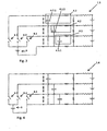
- Fig. 1 shows a circuit of a power cell, e.g. a fuel cell, electrolytic cell or battery system 1.1 according to a first embodiment of the present invention which can be used with a device for detecting connectivity in the CVM.
- Power cells according to the embodiments of the present invention can be used in a wide variety of application, for example, to power automotive vehicles such as buses, cars, motobicycles, scooters, bicycles; or boats, trains, vending machines, vacuum cleaners, motorway road signs, electronic devicess, hospital equipment, wastewater treatment plants, etc.
- a first fuel cell 2.1, a second fuel cell 2.2 and a third fuel cell 2.3 are arranged in the order mentioned in a serial connection.
- a ground wire or cable 3.0 is optionally connected to a first pole, e.g. the minus pole of the first fuel cell 2.1, whereby the minus pole of the first fuel cell is the first pole, e.g. the minus pole of the fuel cell system.
- a first wire 3.1 is connected on one side to the second pole, e.g.
- a first low-pass filter 4.1 which comprises a first charge storage device, e.g. capacitor 4.1.1 and a first active resistance 4.1.2.
- a first input resistance 5.1 is connected to the first wire 3.1 and the ground wire or cable 3.0 and operates as a shunt resistor.
- An earth-resistance 6 connects the ground wire or cable 3.0 and the earth resistance 6, respectively, to the capacitance 4.1.1 of the first low-pass filter 4.1.
- a second wire 3.2 is on one side connected to the second pole, e.g. positive pole of the second fuel cell 2.2 and the first pole, e.g. minus pole of a third fuel cell 2.3, respectively, and on the other side to a second low-pass filter 4.2, which comprises a second charge storage device, e.g. a second capacitance 4.2.1 and a second active resistance 4.2.2.
- the second capacitance 4.2.1 of the second low-pass filter 4.2 is connected to the output of the first low-pass filter 4.1 and a second input resistance 5.2 connects the input of the second low-pass filter 4.2 and the second wire 3.2, respectively, to the input of the first low-pass filter 4.1 and acts as a shunt resistor.
- a third wire 3.3 is on one side connected to the second pole, e.g. positive pole of the third fuel cell 2.3, which is the second pole, e.g. positive pole of the fuel cell system and on the other side to a third low-pass filter 4.3, which comprises a third charge storage device, e.g. a third capacitance 4.3.1 and a third active resistance 4.3.2.
- a third input resistance 5.3 connects the input of the third low-pass filter 4.3 and the third wire 3.3, respectively, to the input of the second low-pass filter 4.2 and acts as a shunt resistor.
- n th wire 3.n is on one side connected to the second pole, e.g. positive pole of the n th fuel cell 2.n, which is the second pole, e.g. positive pole of the fuel cell system and on the other side to an n th low-pass filter 4.n, which comprises an n th charge storage device, e.g. an n th capacitance 4.n.1 and an n th active resistance 4.n.2.
- n th input resistance 5.n connects the input of the n th low-pass filter 4.n and the n th wire 3.n, respectively, to the input of the n-1 th low-pass filter 4.n-1 and acts as a shunt resistor.
- a first differential output 7.1 of the first low-pass filter 4.1 is connected to a first voltage monitoring unit 10.1 that is optionally a first analogue to digital (A/D) converter and can be bypassed by a first switch 8.1.
- a second differential output 7.2 of the second low-pass filter 4.2 is also connected to a second voltage monitoring unit 10.2 that is optionally a second analogue to digital converter and can also be bypassed by a second switch 8.2.
- a third differential output 7.3 of the third low-pass filter 4.3 is connected to a third voltage monitoring unit 10.3 that is optionally a third analogue to digital converter and can be bypassed with a third switch 8.3 too.
- the three voltage monitoring units (that is optionally the three analogue to digital converters) associated to outputs 7.1, 7.2 and 7.3 are part of a CVM. Furthermore, all input resistances 5.1, 5.2 and 5.3 are of equal value, all of the capacitances of the three charge storage devices 4.1.1, 4.2.1 and 4.3.1 are of equal value, and all three of the active resistances 4.1.2, 4.2.2 and 4.3.2 are of equal value. Further, the input resistances 5.1, 5.2 and 5.3 are of much larger value than the corresponding active resistances 4.1.2, 4.2.2 and 4.3.2, e.g. 5 times, 10 times 20 times bigger.
- the switches 8.1, 8.2 and 8.3 need not have ground potential on their normally open pole. An intermediate voltage between the voltage of a power cell and ground or a voltage higher than the voltage of a power cell would also be able to be used.
- an n th differential output 7.n of the n th low-pass filter 4.n is connected to an n th voltage monitoring unit that is optionally a first analogue to digital (A/D) converter and can be bypassed by an n th switch 8.n.
- the n th voltage monitoring unit associated to output 7.n is also part of the CVM.
- the resistance value of the n th input resistance 5.n is the same for all input resistances 5.1, 5.2
- the capacitance of the n th charge storage device is the same as all of the capacitances 4.1.1,4.2.1 and 4.3.1
- the n th active resistance is the same as all of the active resistances 4.1.2, 4.2.2 and 4.3.2.
- the three switches 8.1, 8.2 and 8.3 are closed simultaneously, which leads to an abrupt discharge of the three capacitances 4.1.1, 4.2.1 and 4.3.1.
- the switches 8.1, 8.2 and 8.3 are then opened simultaneously and recharging of the three capacitances 4.1.1, 4.2.1 takes place. If one of the wires, in this case for example the second wire 3.2, is disconnected, the second capacitance 4.2.1 is charged through the adjacent input resistance and low-pass filter of the neighbouring cell, in this case the third input resistance 5.3 and the third low-pass filter 4.3, which leads to a different dynamic response of the voltage on the relevant capacitor, e.g.
- the second voltage monitoring unit e.g. analogue to digital converter, measures the dynamic response, e.g. measures after a predefined time delay after opening of the second switch 8.2, the output voltage of the output 7.2.
- the second output voltage 7.2 indicates a bad connection, in this case for the second wire 3.2, if the dynamic response differs from normal operation, e.g. if the second output voltage 7.2 is at the measuring time lower than the other output voltages.
- the power cells 2.1 to 2.3 are connected in a first ladder circuit comprising the power cells 2.1 to 2.3 and first resistors 5.1 to 5.3.
- the "rungs" of the ladder are formed by the connections 3.0 to 3.3 which form first nodes between the power cells 2.1 to 2.3.
- the resistors 5.1 to 5.3 are also connected in a second ladder circuit with capacitors 4.1.1 to 4.3.1.
- Second nodes between the resistors 5.1 to 5.3 are connected to third nodes between the charge storage devices, e.g. capacitors 4.1.1 to 4.3.1 via second resistors 4.1.2 to 4.3.2.
- the third nodes are connected to voltage monitoring units, e.g.
- analogue to digital converters as described above as well as to short-circuiting switches 8.1 to 8.3. Operation is as described previously. Use is made of the dynamic change of the voltages on the third nodes as measured by the voltage monitoring units, e.g. analogue to digital converters, to determine if there is a discontinuity in the wiring.
- a bad connection in the ground wire 3.0 leads to a differential voltage output of 0 V at output 7.1 which is sufficient to indicate a discontinuity.
- a circuit according to a second embodiment as shown in Fig. 2 is preferred.
- the circuit according to Fig. 2 is equivalent to the circuit according to Fig. 1 , with the difference, that an external voltage source 9 is connected with one pole, e.g. its positive pole to the first switch 8.1 and with its other pole, e.g. its negative pole to the grounding resistance 6, whereby the voltage of the external voltage source 9 can be any suitable arbitrary voltage, e.g. the voltage supply of the voltage monitoring circuit or a reference voltage that differs from the nominal voltage of one power cell.
- the first switch 8.1 If the grounding wire or cable 3.0 is disconnected and the first switch 8.1 is closed an electric current of the external voltage supply 9 flows through the first low-pass filter 4.1, the first input resistance 5.1 and the grounding resistance 6.
- the first capacitance 4.1.1 discharges or charges, whereby the charging/discharging dynamic response is much slower, e.g. the voltage at half-life is much lower than in case of an intact grounding wire or cable 3.0 which can be detected by the relevant voltage monitoring unit, e.g. analogue to digital converter.
- a connectivity check according to Fig. 1 and/or Fig. 2 might give false results.
- a circuit of a power cell e.g. fuel cell system 1.3 according a third embodiment of the present invention as shown to Fig. 3 can be used, where the second pole, e.g. the positive pole of an external voltage source 9 is connected to each of the switches 8.1, 8.2 and 8.3 and the first pole, e.g. negative pole of the external voltage source 9 is connected to the grounding resistance 6.
- the output voltage of the external voltage source 9 can be of any arbitrary voltage.
- the first to third charge storage devices e.g.
- first capacitance 4.1.1, the second capacitance 4.2.1 and the third capacitance 4.3.1 are all connected between the corresponding resistance 4.1.2, 4.2.2 and 4.2.3 and the ground, instead of being connected to the output of the adjacent low-pass filter, which is the case for the circuits 1.1 and 1.2 corresponding to Fig. 1 and Fig. 2 .
- the first to third charge storage devices e.g. the first capacitance 4.1.1, the second capacitance 4.2.1 and the third capacitance 4.3.1 and the corresponding resistances 4.1.2,4.2.2 and 4.2.3 form low pass filters.
- the power cells 2.1 to 2.3 are connected in a first ladder circuit comprising the power cells 2.1 to 2.3 and first resistors 5.1 to 5.3.
- the "rungs" of the ladder are formed by the connections 3.0 to 3.3 which form first nodes between the power cells 2.1 to 2.3.
- Second nodes between the resistors 5.1 to 5.3 are individually connected to ground via series connections of charge storage devices, e.g. capacitors 4.1.1 to 4.3.1 and second resistors 4.1.2 to 4.3.2, in respective pairs.
- the resistors 4.1.2 to 4.3.2 are connected with normally open poles of switches 8.1 to 8.3 via third nodes.
- the third nodes are connected to voltage monitoring units, e.g.
- the second pole e.g. the positive pole of an external voltage source 9 is connected to each of the switches 8.1, 8.2 and 8.3 and the first pole, e.g. negative pole of the external voltage source 9 is connected to the grounding resistance 6.
- the output voltage of the external voltage source 9 can be of any arbitrary voltage.
- the three power cells e.g. fuel cells show a voltage of zero volts the three input resistances 5.1, 5.2 and 5.3 can be considered as short-circuited, in normal operation.
- a transection of the second wire 3.2 for instance, a closed second switch 8.2 makes the electrical current of the external voltage source 9 flow through the second input resistance 5.2 and the third input resistance 5.3, which makes the discharging half-life of the second capacitance 4.2.1 higher than in a normal operation. This fact is detectable by the CVM at the second output 7.2.
- circuit 1.4 the external voltage supply 9 is connected with its second pole, e.g. positive pole only to the second switch 8.2 and the third switch 8.3, but not to the first switch 8.1, and the first pole, e.g. the negative pole of the external voltage source 9 is connected to the first switch 8.1 and the resistance 6.
- the first switch 8.1 is closed the first capacitance 4.1.1 is at zero volts, since both electrodes of the first capacitance 4.1.1 are connected to the same electrical potential. If the first switch 8.1 is opened again the first capacitance 4.1.1 is charged through the first active resistance 4.1.2 and the ground resistance 6, since the first input resistance 5.1 is short-circuited by the first fuel cell 2.1. If the ground wire or cable 3.0 is disconnected the first input resistance 5.1 is not short-circuited anymore and the first capacitance 4.1.1 is charged through the first active resistance 4.1.2, the ground resistance 6 and the first input resistance 5.1, which makes the charging half-life of the first capacitance 4.1.1 much longer. This fact is detectable by the CVM via the first output 7.1.
- the voltage monitoring units include analogue to digital converters. These may be part of a microcontroller, which can also include the three switches as well.
- the external voltage source 9 can also be part of the microcontroller, which simplifies the switching of the external voltage source 9 between the three switches 8.1, 8.2 and 8.3. Hence the switching of the three switches 8.1, 8.2 and 8.3 can also be controlled by the microcontroller.
- the microcontroller can have analog input pins that can be used to monitor the voltages 7.1 to 7.3, e.g. the microcontroller has an anlaogue to digital converter for converting the analogue input values to digital values.
- the analogue inputs can be programmed to temporarily function as digital output pins with a low logic level signal and optionally a high level logic signal.
- the anlogue input pins can be monitoring the voltages 7.1...7.3 of any of the above embodiments (in which case the switches 8.1-3 are open circuit) or they can switch to a low logic level which effectively implements a shorted switch.
- a high level digital output is provided on one pin thus implementing the switching to an external voltage source as for example to switch 8.1 of figure 2 , charging the capacitor 4.1.1 to the microcontroller's power supply.
- the microcontroller not only measures the cell voltages, e.g. via analogue inputs, and also to provide the switching functions of switches 8.1-3 but it is also programmed to adapt the VSU setup to any one of the embodiments shown in Figs. 1 to 4 .
- the microcontroller may include decision software to decide on which setup is most appropriate (e.g. which of the configurations of figures 1, 2 , 3 or 4 is best to implement).
- the monitoring of the dynamic voltage response of the charging capacitors time after opening 8.1..8.3, e.g. up to the time of the acquisition of the voltages 7.1 to 7.3 can easily be performed by the microcontroller. It can also compare the values acquired during the connectivity check to the expected value and report only the state of the connection, e.g. to a main controller (not shown) of the CVM.
- the microcontroller may be implemented as hardware, computer software, or combinations of both.
- the microcontroller may include a general purpose processor, an embedded processor, an application specific integrated circuit (ASIC), a field programmable gate array (FPGA) or other programmable logic device, discrete gate or transistor logic, discrete hardware components, or any combination designed to perform the functions described herein.
- a processor may also be implemented as a combination of computing devices, e.g., a combination of an FPGA and a microprocessor, a plurality of microprocessors, one or more microprocessors in conjunction with an FPGA, or any other such configuration.
- All connectivity checks for all cells in a stack can be performed by all voltage monitoring units simultaneously.
- the result of the connectivity check is only one bit per acquisition channel so the communication overhead to report the results back to the main controller is very limited.
Landscapes
- Engineering & Computer Science (AREA)
- Manufacturing & Machinery (AREA)
- Chemical & Material Sciences (AREA)
- Chemical Kinetics & Catalysis (AREA)
- Electrochemistry (AREA)
- General Chemical & Material Sciences (AREA)
- General Physics & Mathematics (AREA)
- Physics & Mathematics (AREA)
- Sustainable Development (AREA)
- Sustainable Energy (AREA)
- Life Sciences & Earth Sciences (AREA)
- Microelectronics & Electronic Packaging (AREA)
- Fuel Cell (AREA)
- Secondary Cells (AREA)
- Testing Of Short-Circuits, Discontinuities, Leakage, Or Incorrect Line Connections (AREA)
- Charge And Discharge Circuits For Batteries Or The Like (AREA)
Claims (12)
- Système de cellule de puissance (1.1) avec un dispositif pour détecter une discontinuité dans des connexions électriques à des cellules de puissance (2.1, 2.2, ....) dans le système de cellule de puissance (1.1), le système comprenant :une pluralité de cellules de puissance (2.1, 2.2, ....) et une pluralité de filtres électroniques (4.1, 4.2, ...) chacun ayant une connexion à une électrode d'une cellule de puissance, chacun de la pluralité de filtres électroniques comprenant une première résistance (4.1.2, 4.2.4, ...) et un condensateur (4.1.1, 4.1.2, ....) connecté à la première résistance, le système étant conçu pour :décharger simultanément les condensateurs tout en maintenant les connexions aux cellules de puissance,recharger simultanément les condensateurs à partir des cellules de puissance, comprenant en outre une unité de contrôle de tension pour contrôler une tension dynamique sur les condensateurs pour déterminer s'il y a une discontinuité dans des connexions électriques aux cellules de puissance.
- Système de cellule de puissance selon la revendication 1, dans lequel le dispositif pour la détection comprend :une pluralité de n secondes résistances (5.1, 5.2, ...), chacune de la pluralité de n secondes résistances étant connectée en tant que résistance de shunt d'une cellule de puissance associée de sorte que les n cellules de puissance et les n secondes résistances forment un circuit d'échelle,n filtres électroniques (4.1, 4,2, ...), chaque filtre électronique ayant une première connexion à un premier noeud du circuit d'échelle entre deux des secondes résistances (5.1, 5.2, ...), dans lequel le dispositif comprend en outre n commutateurs (8.1, 8.2, ...), chacun des n commutateurs étant connecté à une sortie d'un filtre électronique.
- Système de cellule de puissance selon la revendication 2, dans lequel les filtres électroniques sont fournis en tant que filtres passe-bas.
- Système de cellule de puissance selon la revendication 2 ou 3, dans lequel chacune des premières résistances est respectivement connectée à une première résistance adjacente.
- Système de cellule de puissance selon la revendication 3 ou 4, dans lequel la totalité des premières résistances sont de valeur égale.
- Système de cellule de puissance selon l'une quelconque des revendications précédentes, dans lequel une sortie de chaque filtre électronique est connectée à l'unité de contrôle de tension.
- Système de cellule de puissance selon l'une quelconque des revendications précédentes, dans lequel chacune des cellules de puissance sert à la connexion avec une connexion particulière à une entrée d'un filtre électronique correspondant.
- Système de cellule de puissance selon l'une quelconque des revendications précédentes, dans lequel chacune des cellules de puissance sert à la connexion à une cellule de puissance adjacente dans une connexion en série.
- Système de cellule de puissance selon l'une quelconque des revendications précédentes, dans lequel les impédances des filtres électroniques sont égales les unes aux autres.
- Système de cellule de puissance selon l'une quelconque des revendications 6 à 9, dans lequel une source de tension externe est agencée pour connexion entre un des commutateurs et un pôle moins du système de cellule de puissance.
- Système de cellule de puissance selon l'une quelconque des revendications 6 à 9, dans lequel une source de tension externe est agencée pour connexion entre chacun des commutateurs et un premier pôle du système de cellule de puissance.
- Système de cellule de puissance selon la revendication 11, dans lequel le commutateur pour couplage à la cellule de puissance comprenant le premier pôle du système de cellule de puissance est connecté au premier pôle de la source de tension externe.
Priority Applications (1)
| Application Number | Priority Date | Filing Date | Title |
|---|---|---|---|
| EP10710019.0A EP2409169B1 (fr) | 2009-03-18 | 2010-03-18 | Système de cellules électriques doté d'un moyen de détection de discontinuités |
Applications Claiming Priority (3)
| Application Number | Priority Date | Filing Date | Title |
|---|---|---|---|
| EP20090155534 EP2230529B1 (fr) | 2009-03-18 | 2009-03-18 | Système de cellules électriques doté d'un moyen de détection de discontinuités |
| EP10710019.0A EP2409169B1 (fr) | 2009-03-18 | 2010-03-18 | Système de cellules électriques doté d'un moyen de détection de discontinuités |
| PCT/EP2010/053550 WO2010106141A1 (fr) | 2009-03-18 | 2010-03-18 | Système de piles doté de moyens de détection d'une interruption |
Publications (2)
| Publication Number | Publication Date |
|---|---|
| EP2409169A1 EP2409169A1 (fr) | 2012-01-25 |
| EP2409169B1 true EP2409169B1 (fr) | 2015-09-09 |
Family
ID=41172276
Family Applications (2)
| Application Number | Title | Priority Date | Filing Date |
|---|---|---|---|
| EP20090155534 Active EP2230529B1 (fr) | 2009-03-18 | 2009-03-18 | Système de cellules électriques doté d'un moyen de détection de discontinuités |
| EP10710019.0A Active EP2409169B1 (fr) | 2009-03-18 | 2010-03-18 | Système de cellules électriques doté d'un moyen de détection de discontinuités |
Family Applications Before (1)
| Application Number | Title | Priority Date | Filing Date |
|---|---|---|---|
| EP20090155534 Active EP2230529B1 (fr) | 2009-03-18 | 2009-03-18 | Système de cellules électriques doté d'un moyen de détection de discontinuités |
Country Status (6)
| Country | Link |
|---|---|
| US (2) | US8907676B2 (fr) |
| EP (2) | EP2230529B1 (fr) |
| JP (1) | JP5756078B2 (fr) |
| DK (2) | DK2230529T3 (fr) |
| ES (2) | ES2395695T3 (fr) |
| WO (1) | WO2010106141A1 (fr) |
Families Citing this family (21)
| Publication number | Priority date | Publication date | Assignee | Title |
|---|---|---|---|---|
| DE102011004288A1 (de) * | 2011-02-17 | 2012-08-23 | Robert Bosch Gmbh | Anordnung und Verfahren zur Verbindungsabrisserkennung an einem Schaltungsteil mit kapazitivem Verhalten |
| US9065096B2 (en) | 2011-02-24 | 2015-06-23 | Samsung Sdi Co., Ltd. | Fuel cell stack |
| US9340122B2 (en) | 2011-05-31 | 2016-05-17 | Hitachi Automotive Systems, Ltd. | Battery system monitoring apparatus |
| US9927465B2 (en) | 2011-09-14 | 2018-03-27 | Honda Motor Co., Ltd. | Voltage measuring device |
| JP5775935B2 (ja) * | 2011-10-20 | 2015-09-09 | 日立オートモティブシステムズ株式会社 | 電池システムの監視装置およびこれを備えた蓄電装置 |
| US9448272B2 (en) | 2011-11-09 | 2016-09-20 | Danfoss A/S | Earthed connection detection |
| US9837837B2 (en) * | 2012-11-19 | 2017-12-05 | Byd Company Limited | Protective device and protective system for battery assembly which detects discontinuities through voltage monitoring |
| CN103837831A (zh) * | 2012-11-30 | 2014-06-04 | 凯迈(洛阳)电子有限公司 | 一种电池有效性分析模型 |
| EP2988144B1 (fr) * | 2013-04-19 | 2018-03-07 | Hitachi Automotive Systems, Ltd. | Dispositif de surveillance de système de batterie |
| DE112014002675T5 (de) * | 2013-06-04 | 2016-02-18 | Trw Automotive U.S. Llc | Optimierte Spannungsversorgungsarchitektur |
| LT2866354T (lt) * | 2013-10-25 | 2019-10-10 | Vito Nv (Vlaamse Instelling Voor Technologisch Onderzoek Nv) | Būdas ir sistema energijos bei duomenų impulsams perduoti per magistralę |
| FR3013460B1 (fr) * | 2013-11-21 | 2018-01-05 | Commissariat A L'energie Atomique Et Aux Energies Alternatives | Procede de detection d'un dysfonctionnement d'un systeme de controle de batterie |
| US9945886B2 (en) * | 2014-09-25 | 2018-04-17 | Sanyo Electric Co., Ltd. | Electrical current detection device equipped with shunt resistor, and power supply device |
| CN104316818B (zh) * | 2014-10-29 | 2017-06-16 | 青岛鸿瑞电力工程咨询有限公司 | 电缆断线在线检测方法 |
| JP6268607B2 (ja) | 2014-11-27 | 2018-01-31 | トヨタ自動車株式会社 | 燃料電池の検査方法 |
| JP2017032349A (ja) * | 2015-07-30 | 2017-02-09 | 矢崎総業株式会社 | 二次電池状態検出装置 |
| CN108432082B (zh) * | 2015-12-22 | 2022-05-13 | 威拓股份有限公司 | 一种使用仅一个开关进行的连通性检查的方法和装置 |
| EP3398239A1 (fr) * | 2015-12-29 | 2018-11-07 | Vito NV | Dispositif et procédé de reconfiguration d'un dispositif de stockage d'énergie rechargeable en chaînes de connexion de batteries séparées |
| US10305271B2 (en) | 2016-06-30 | 2019-05-28 | Microsoft Technology Licensing, Llc | Multi-pack and component connectivity detection |
| KR102895998B1 (ko) * | 2019-05-16 | 2025-12-04 | 현대자동차주식회사 | 연료전지의 운전 제어시스템 및 제어방법 |
| WO2023199364A1 (fr) * | 2022-04-15 | 2023-10-19 | Alberto Bauer | Procédé d'estimation de la valeur de tension |
Family Cites Families (19)
| Publication number | Priority date | Publication date | Assignee | Title |
|---|---|---|---|---|
| US4187504A (en) * | 1978-02-03 | 1980-02-05 | Midland-Ross Corporation | Fault monitoring and indicator system |
| US4228394A (en) * | 1978-11-16 | 1980-10-14 | Beckman Instruments, Inc. | Digital ohmmeter with electrical continuity tester |
| US4433294A (en) * | 1981-06-05 | 1984-02-21 | Firing Circuits, Inc. | Method and apparatus for testing a battery |
| US6130530A (en) * | 1997-12-22 | 2000-10-10 | Hd Electric Company | Tester for power transformers and capacitors |
| TW472426B (en) * | 1998-10-06 | 2002-01-11 | Hitachi Ltd | Battery apparatus and control system therefor |
| US6211513B1 (en) * | 1998-10-30 | 2001-04-03 | Avaya Technology Corp. | Automated test system and method for device having circuit and ground connections |
| US6420877B1 (en) * | 1999-04-14 | 2002-07-16 | Group Dekko Services, Llc | Continuity totalizer/analyzer |
| JP3300309B2 (ja) * | 1999-10-19 | 2002-07-08 | 本田技研工業株式会社 | 電池電圧測定装置 |
| JP3696124B2 (ja) * | 2001-05-17 | 2005-09-14 | 三洋電機株式会社 | 組電池の電圧検出回路 |
| US6998819B2 (en) * | 2002-05-28 | 2006-02-14 | Ford Global Technologies, Llc | Current leakage detection in high voltage battery pack |
| JP4842530B2 (ja) | 2004-10-06 | 2011-12-21 | 株式会社日立製作所 | 燃料電池システム及びその異常診断方法 |
| JP4186916B2 (ja) * | 2004-11-18 | 2008-11-26 | 株式会社デンソー | 組電池管理装置 |
| JP4291769B2 (ja) | 2004-11-30 | 2009-07-08 | 本田技研工業株式会社 | 接触検知方法 |
| US7976790B2 (en) | 2005-01-12 | 2011-07-12 | Vasco Cheung | Method and apparatus for the extraction of plant constituents |
| JP4583219B2 (ja) * | 2005-03-30 | 2010-11-17 | 三洋電機株式会社 | 車両用の電源装置 |
| WO2007119682A1 (fr) | 2006-04-13 | 2007-10-25 | Panasonic Corporation | Bloc-batterie et procédé de détection de disjonction du bloc-batterie |
| US7612530B2 (en) * | 2006-11-21 | 2009-11-03 | Industrial Technology Research Institute | Bridge battery voltage equalizer |
| EP1936777B1 (fr) * | 2006-12-18 | 2017-11-01 | Nissan Motor Ltd. | Dispositif de diagnostic d'anomalies |
| US7626359B2 (en) * | 2007-10-23 | 2009-12-01 | IKS Co., Ltd | Apparatus and method for charging and discharging serially-connected batteries |
-
2009
- 2009-03-18 EP EP20090155534 patent/EP2230529B1/fr active Active
- 2009-03-18 ES ES09155534T patent/ES2395695T3/es active Active
- 2009-03-18 DK DK09155534T patent/DK2230529T3/da active
-
2010
- 2010-03-18 JP JP2012500257A patent/JP5756078B2/ja not_active Expired - Fee Related
- 2010-03-18 ES ES10710019.0T patent/ES2553856T3/es active Active
- 2010-03-18 EP EP10710019.0A patent/EP2409169B1/fr active Active
- 2010-03-18 US US13/254,274 patent/US8907676B2/en active Active
- 2010-03-18 DK DK10710019.0T patent/DK2409169T3/en active
- 2010-03-18 WO PCT/EP2010/053550 patent/WO2010106141A1/fr not_active Ceased
-
2014
- 2014-11-06 US US14/534,630 patent/US9638759B2/en not_active Expired - Fee Related
Also Published As
| Publication number | Publication date |
|---|---|
| EP2230529B1 (fr) | 2012-11-14 |
| US20110316549A1 (en) | 2011-12-29 |
| DK2230529T3 (da) | 2012-12-17 |
| US9638759B2 (en) | 2017-05-02 |
| US20150108990A1 (en) | 2015-04-23 |
| DK2409169T3 (en) | 2015-12-21 |
| EP2230529A1 (fr) | 2010-09-22 |
| EP2409169A1 (fr) | 2012-01-25 |
| ES2395695T3 (es) | 2013-02-14 |
| JP5756078B2 (ja) | 2015-07-29 |
| ES2553856T3 (es) | 2015-12-14 |
| US8907676B2 (en) | 2014-12-09 |
| JP2012520996A (ja) | 2012-09-10 |
| WO2010106141A1 (fr) | 2010-09-23 |
Similar Documents
| Publication | Publication Date | Title |
|---|---|---|
| EP2409169B1 (fr) | Système de cellules électriques doté d'un moyen de détection de discontinuités | |
| CN102539993B (zh) | 检测集成电路和多单元电池组之间的开路连接的系统和方法 | |
| CN101752844B (zh) | 保护电池组的设备、系统及方法 | |
| US8163411B2 (en) | Abnormality detection apparatus for battery pack | |
| US9128161B2 (en) | Voltage monitoring device | |
| US11892518B2 (en) | Method of operating battery management systems, corresponding device and vehicle | |
| JP6137007B2 (ja) | 異常検出装置 | |
| US10141752B2 (en) | Drawback resistant battery monitoring unit | |
| EP1585207A2 (fr) | Dispositif d'alimentation de puissance | |
| KR101473395B1 (ko) | 고장 자가 진단 기능을 구비한 절연 저항 측정 장치 및 이를 이용한 고장 자가 진단 방법 | |
| US12571849B2 (en) | Battery measurement device and battery measurement method | |
| JP6695032B2 (ja) | 異常検出装置 | |
| US12174267B2 (en) | Earth leakage detecting device, and vehicular power supply system | |
| CN100413141C (zh) | 带有检测单元的蓄电池组 | |
| ES2869451B2 (es) | Sistema y metodo de localizacion de faltas a tierra en instalaciones electricas de corriente continua | |
| US20250076353A1 (en) | System and method for isolation resistance measurement | |
| CN215728549U (zh) | 一种新能源汽车高压环路互锁检测电路 | |
| KR20240111988A (ko) | 연료전지 제어장치 및 그 방법 | |
| JP2018196293A (ja) | 組電池の故障検出装置 |
Legal Events
| Date | Code | Title | Description |
|---|---|---|---|
| PUAI | Public reference made under article 153(3) epc to a published international application that has entered the european phase |
Free format text: ORIGINAL CODE: 0009012 |
|
| 17P | Request for examination filed |
Effective date: 20111018 |
|
| AK | Designated contracting states |
Kind code of ref document: A1 Designated state(s): AT BE BG CH CY CZ DE DK EE ES FI FR GB GR HR HU IE IS IT LI LT LU LV MC MK MT NL NO PL PT RO SE SI SK SM TR |
|
| DAX | Request for extension of the european patent (deleted) | ||
| REG | Reference to a national code |
Ref country code: DE Ref legal event code: R079 Ref document number: 602010027354 Country of ref document: DE Free format text: PREVIOUS MAIN CLASS: G01R0031360000 Ipc: G01R0031280000 |
|
| GRAP | Despatch of communication of intention to grant a patent |
Free format text: ORIGINAL CODE: EPIDOSNIGR1 |
|
| RIC1 | Information provided on ipc code assigned before grant |
Ipc: G01R 31/02 20060101ALI20140523BHEP Ipc: G01R 31/28 20060101AFI20140523BHEP Ipc: G01R 31/36 20060101ALI20140523BHEP Ipc: H01M 10/42 20060101ALI20140523BHEP Ipc: H01M 8/04 20060101ALI20140523BHEP Ipc: H01M 16/00 20060101ALI20140523BHEP Ipc: H01M 10/48 20060101ALI20140523BHEP Ipc: H01M 8/10 20060101ALI20140523BHEP |
|
| INTG | Intention to grant announced |
Effective date: 20140616 |
|
| GRAP | Despatch of communication of intention to grant a patent |
Free format text: ORIGINAL CODE: EPIDOSNIGR1 |
|
| INTG | Intention to grant announced |
Effective date: 20150109 |
|
| GRAP | Despatch of communication of intention to grant a patent |
Free format text: ORIGINAL CODE: EPIDOSNIGR1 |
|
| INTG | Intention to grant announced |
Effective date: 20150603 |
|
| GRAS | Grant fee paid |
Free format text: ORIGINAL CODE: EPIDOSNIGR3 |
|
| GRAA | (expected) grant |
Free format text: ORIGINAL CODE: 0009210 |
|
| AK | Designated contracting states |
Kind code of ref document: B1 Designated state(s): AT BE BG CH CY CZ DE DK EE ES FI FR GB GR HR HU IE IS IT LI LT LU LV MC MK MT NL NO PL PT RO SE SI SK SM TR |
|
| REG | Reference to a national code |
Ref country code: GB Ref legal event code: FG4D |
|
| REG | Reference to a national code |
Ref country code: AT Ref legal event code: REF Ref document number: 748563 Country of ref document: AT Kind code of ref document: T Effective date: 20150915 Ref country code: CH Ref legal event code: EP |
|
| REG | Reference to a national code |
Ref country code: IE Ref legal event code: FG4D |
|
| REG | Reference to a national code |
Ref country code: DE Ref legal event code: R096 Ref document number: 602010027354 Country of ref document: DE |
|
| REG | Reference to a national code |
Ref country code: ES Ref legal event code: FG2A Ref document number: 2553856 Country of ref document: ES Kind code of ref document: T3 Effective date: 20151214 |
|
| REG | Reference to a national code |
Ref country code: DK Ref legal event code: T3 Effective date: 20151214 |
|
| REG | Reference to a national code |
Ref country code: SE Ref legal event code: TRGR |
|
| PG25 | Lapsed in a contracting state [announced via postgrant information from national office to epo] |
Ref country code: LT Free format text: LAPSE BECAUSE OF FAILURE TO SUBMIT A TRANSLATION OF THE DESCRIPTION OR TO PAY THE FEE WITHIN THE PRESCRIBED TIME-LIMIT Effective date: 20150909 Ref country code: GR Free format text: LAPSE BECAUSE OF FAILURE TO SUBMIT A TRANSLATION OF THE DESCRIPTION OR TO PAY THE FEE WITHIN THE PRESCRIBED TIME-LIMIT Effective date: 20151210 Ref country code: LV Free format text: LAPSE BECAUSE OF FAILURE TO SUBMIT A TRANSLATION OF THE DESCRIPTION OR TO PAY THE FEE WITHIN THE PRESCRIBED TIME-LIMIT Effective date: 20150909 |
|
| REG | Reference to a national code |
Ref country code: NO Ref legal event code: T2 Effective date: 20150909 |
|
| REG | Reference to a national code |
Ref country code: LT Ref legal event code: MG4D Ref country code: NL Ref legal event code: FP |
|
| PG25 | Lapsed in a contracting state [announced via postgrant information from national office to epo] |
Ref country code: HR Free format text: LAPSE BECAUSE OF FAILURE TO SUBMIT A TRANSLATION OF THE DESCRIPTION OR TO PAY THE FEE WITHIN THE PRESCRIBED TIME-LIMIT Effective date: 20150909 |
|
| REG | Reference to a national code |
Ref country code: FR Ref legal event code: PLFP Year of fee payment: 7 |
|
| PG25 | Lapsed in a contracting state [announced via postgrant information from national office to epo] |
Ref country code: EE Free format text: LAPSE BECAUSE OF FAILURE TO SUBMIT A TRANSLATION OF THE DESCRIPTION OR TO PAY THE FEE WITHIN THE PRESCRIBED TIME-LIMIT Effective date: 20150909 Ref country code: SK Free format text: LAPSE BECAUSE OF FAILURE TO SUBMIT A TRANSLATION OF THE DESCRIPTION OR TO PAY THE FEE WITHIN THE PRESCRIBED TIME-LIMIT Effective date: 20150909 Ref country code: IS Free format text: LAPSE BECAUSE OF FAILURE TO SUBMIT A TRANSLATION OF THE DESCRIPTION OR TO PAY THE FEE WITHIN THE PRESCRIBED TIME-LIMIT Effective date: 20160109 |
|
| PGFP | Annual fee paid to national office [announced via postgrant information from national office to epo] |
Ref country code: CZ Payment date: 20160317 Year of fee payment: 7 |
|
| PG25 | Lapsed in a contracting state [announced via postgrant information from national office to epo] |
Ref country code: PL Free format text: LAPSE BECAUSE OF FAILURE TO SUBMIT A TRANSLATION OF THE DESCRIPTION OR TO PAY THE FEE WITHIN THE PRESCRIBED TIME-LIMIT Effective date: 20150909 Ref country code: RO Free format text: LAPSE BECAUSE OF FAILURE TO SUBMIT A TRANSLATION OF THE DESCRIPTION OR TO PAY THE FEE WITHIN THE PRESCRIBED TIME-LIMIT Effective date: 20150909 Ref country code: PT Free format text: LAPSE BECAUSE OF FAILURE TO SUBMIT A TRANSLATION OF THE DESCRIPTION OR TO PAY THE FEE WITHIN THE PRESCRIBED TIME-LIMIT Effective date: 20160111 |
|
| REG | Reference to a national code |
Ref country code: DE Ref legal event code: R097 Ref document number: 602010027354 Country of ref document: DE |
|
| PLBE | No opposition filed within time limit |
Free format text: ORIGINAL CODE: 0009261 |
|
| STAA | Information on the status of an ep patent application or granted ep patent |
Free format text: STATUS: NO OPPOSITION FILED WITHIN TIME LIMIT |
|
| 26N | No opposition filed |
Effective date: 20160610 |
|
| PG25 | Lapsed in a contracting state [announced via postgrant information from national office to epo] |
Ref country code: SI Free format text: LAPSE BECAUSE OF FAILURE TO SUBMIT A TRANSLATION OF THE DESCRIPTION OR TO PAY THE FEE WITHIN THE PRESCRIBED TIME-LIMIT Effective date: 20150909 |
|
| PG25 | Lapsed in a contracting state [announced via postgrant information from national office to epo] |
Ref country code: MC Free format text: LAPSE BECAUSE OF FAILURE TO SUBMIT A TRANSLATION OF THE DESCRIPTION OR TO PAY THE FEE WITHIN THE PRESCRIBED TIME-LIMIT Effective date: 20150909 Ref country code: LU Free format text: LAPSE BECAUSE OF FAILURE TO SUBMIT A TRANSLATION OF THE DESCRIPTION OR TO PAY THE FEE WITHIN THE PRESCRIBED TIME-LIMIT Effective date: 20160318 |
|
| REG | Reference to a national code |
Ref country code: FR Ref legal event code: PLFP Year of fee payment: 8 |
|
| PG25 | Lapsed in a contracting state [announced via postgrant information from national office to epo] |
Ref country code: MT Free format text: LAPSE BECAUSE OF FAILURE TO SUBMIT A TRANSLATION OF THE DESCRIPTION OR TO PAY THE FEE WITHIN THE PRESCRIBED TIME-LIMIT Effective date: 20150909 |
|
| PG25 | Lapsed in a contracting state [announced via postgrant information from national office to epo] |
Ref country code: CZ Free format text: LAPSE BECAUSE OF NON-PAYMENT OF DUE FEES Effective date: 20170318 |
|
| REG | Reference to a national code |
Ref country code: FR Ref legal event code: PLFP Year of fee payment: 9 |
|
| PGFP | Annual fee paid to national office [announced via postgrant information from national office to epo] |
Ref country code: FI Payment date: 20180221 Year of fee payment: 9 |
|
| REG | Reference to a national code |
Ref country code: AT Ref legal event code: UEP Ref document number: 748563 Country of ref document: AT Kind code of ref document: T Effective date: 20150909 |
|
| PG25 | Lapsed in a contracting state [announced via postgrant information from national office to epo] |
Ref country code: CY Free format text: LAPSE BECAUSE OF FAILURE TO SUBMIT A TRANSLATION OF THE DESCRIPTION OR TO PAY THE FEE WITHIN THE PRESCRIBED TIME-LIMIT Effective date: 20150909 Ref country code: HU Free format text: LAPSE BECAUSE OF FAILURE TO SUBMIT A TRANSLATION OF THE DESCRIPTION OR TO PAY THE FEE WITHIN THE PRESCRIBED TIME-LIMIT; INVALID AB INITIO Effective date: 20100318 Ref country code: SM Free format text: LAPSE BECAUSE OF FAILURE TO SUBMIT A TRANSLATION OF THE DESCRIPTION OR TO PAY THE FEE WITHIN THE PRESCRIBED TIME-LIMIT Effective date: 20150909 |
|
| PG25 | Lapsed in a contracting state [announced via postgrant information from national office to epo] |
Ref country code: MT Free format text: LAPSE BECAUSE OF FAILURE TO SUBMIT A TRANSLATION OF THE DESCRIPTION OR TO PAY THE FEE WITHIN THE PRESCRIBED TIME-LIMIT Effective date: 20160331 Ref country code: MK Free format text: LAPSE BECAUSE OF FAILURE TO SUBMIT A TRANSLATION OF THE DESCRIPTION OR TO PAY THE FEE WITHIN THE PRESCRIBED TIME-LIMIT Effective date: 20150909 Ref country code: TR Free format text: LAPSE BECAUSE OF FAILURE TO SUBMIT A TRANSLATION OF THE DESCRIPTION OR TO PAY THE FEE WITHIN THE PRESCRIBED TIME-LIMIT Effective date: 20150909 |
|
| PG25 | Lapsed in a contracting state [announced via postgrant information from national office to epo] |
Ref country code: BG Free format text: LAPSE BECAUSE OF FAILURE TO SUBMIT A TRANSLATION OF THE DESCRIPTION OR TO PAY THE FEE WITHIN THE PRESCRIBED TIME-LIMIT Effective date: 20150909 |
|
| PGFP | Annual fee paid to national office [announced via postgrant information from national office to epo] |
Ref country code: ES Payment date: 20180403 Year of fee payment: 9 |
|
| PG25 | Lapsed in a contracting state [announced via postgrant information from national office to epo] |
Ref country code: FI Free format text: LAPSE BECAUSE OF NON-PAYMENT OF DUE FEES Effective date: 20190318 |
|
| REG | Reference to a national code |
Ref country code: ES Ref legal event code: FD2A Effective date: 20200728 |
|
| PG25 | Lapsed in a contracting state [announced via postgrant information from national office to epo] |
Ref country code: ES Free format text: LAPSE BECAUSE OF NON-PAYMENT OF DUE FEES Effective date: 20190319 |
|
| P01 | Opt-out of the competence of the unified patent court (upc) registered |
Effective date: 20230528 |
|
| PGFP | Annual fee paid to national office [announced via postgrant information from national office to epo] |
Ref country code: DK Payment date: 20250218 Year of fee payment: 16 |
|
| PGFP | Annual fee paid to national office [announced via postgrant information from national office to epo] |
Ref country code: NO Payment date: 20250219 Year of fee payment: 16 |
|
| PGFP | Annual fee paid to national office [announced via postgrant information from national office to epo] |
Ref country code: AT Payment date: 20250220 Year of fee payment: 16 |
|
| PGFP | Annual fee paid to national office [announced via postgrant information from national office to epo] |
Ref country code: IT Payment date: 20250218 Year of fee payment: 16 |
|
| PGFP | Annual fee paid to national office [announced via postgrant information from national office to epo] |
Ref country code: CH Payment date: 20250401 Year of fee payment: 16 |
|
| PGFP | Annual fee paid to national office [announced via postgrant information from national office to epo] |
Ref country code: NL Payment date: 20260219 Year of fee payment: 17 |
|
| PGFP | Annual fee paid to national office [announced via postgrant information from national office to epo] |
Ref country code: SE Payment date: 20260219 Year of fee payment: 17 |
|
| PGFP | Annual fee paid to national office [announced via postgrant information from national office to epo] |
Ref country code: GB Payment date: 20260219 Year of fee payment: 17 |
|
| PGFP | Annual fee paid to national office [announced via postgrant information from national office to epo] |
Ref country code: DE Payment date: 20260219 Year of fee payment: 17 Ref country code: IE Payment date: 20260223 Year of fee payment: 17 |
|
| PGFP | Annual fee paid to national office [announced via postgrant information from national office to epo] |
Ref country code: BE Payment date: 20260219 Year of fee payment: 17 |
|
| PGFP | Annual fee paid to national office [announced via postgrant information from national office to epo] |
Ref country code: FR Payment date: 20260219 Year of fee payment: 17 |