EP2409532B1 - Uplink transmission power control in multi-carrier communication systems - Google Patents
Uplink transmission power control in multi-carrier communication systems Download PDFInfo
- Publication number
- EP2409532B1 EP2409532B1 EP10754056.9A EP10754056A EP2409532B1 EP 2409532 B1 EP2409532 B1 EP 2409532B1 EP 10754056 A EP10754056 A EP 10754056A EP 2409532 B1 EP2409532 B1 EP 2409532B1
- Authority
- EP
- European Patent Office
- Prior art keywords
- pusch
- transmission power
- data
- data channels
- transmission
- Prior art date
- Legal status (The legal status is an assumption and is not a legal conclusion. Google has not performed a legal analysis and makes no representation as to the accuracy of the status listed.)
- Active
Links
Images


Classifications
-
- H—ELECTRICITY
- H04—ELECTRIC COMMUNICATION TECHNIQUE
- H04W—WIRELESS COMMUNICATION NETWORKS
- H04W52/00—Power management, e.g. Transmission Power Control [TPC] or power classes
- H04W52/04—Transmission power control [TPC]
- H04W52/18—TPC being performed according to specific parameters
-
- H—ELECTRICITY
- H04—ELECTRIC COMMUNICATION TECHNIQUE
- H04L—TRANSMISSION OF DIGITAL INFORMATION, e.g. TELEGRAPHIC COMMUNICATION
- H04L5/00—Arrangements affording multiple use of the transmission path
- H04L5/0001—Arrangements for dividing the transmission path
- H04L5/0003—Two-dimensional division
- H04L5/0005—Time-frequency
- H04L5/0007—Time-frequency the frequencies being orthogonal, e.g. OFDM(A) or DMT
-
- H—ELECTRICITY
- H04—ELECTRIC COMMUNICATION TECHNIQUE
- H04L—TRANSMISSION OF DIGITAL INFORMATION, e.g. TELEGRAPHIC COMMUNICATION
- H04L1/00—Arrangements for detecting or preventing errors in the information received
- H04L1/12—Arrangements for detecting or preventing errors in the information received by using return channel
- H04L1/16—Arrangements for detecting or preventing errors in the information received by using return channel in which the return channel carries supervisory signals, e.g. repetition request signals
- H04L1/18—Automatic repetition systems, e.g. Van Duuren systems
- H04L1/1812—Hybrid protocols; Hybrid automatic repeat request [HARQ]
-
- H—ELECTRICITY
- H04—ELECTRIC COMMUNICATION TECHNIQUE
- H04L—TRANSMISSION OF DIGITAL INFORMATION, e.g. TELEGRAPHIC COMMUNICATION
- H04L27/00—Modulated-carrier systems
- H04L27/18—Phase-modulated carrier systems, i.e. using phase-shift keying
-
- H—ELECTRICITY
- H04—ELECTRIC COMMUNICATION TECHNIQUE
- H04L—TRANSMISSION OF DIGITAL INFORMATION, e.g. TELEGRAPHIC COMMUNICATION
- H04L5/00—Arrangements affording multiple use of the transmission path
- H04L5/0001—Arrangements for dividing the transmission path
- H04L5/0003—Two-dimensional division
- H04L5/0005—Time-frequency
- H04L5/0007—Time-frequency the frequencies being orthogonal, e.g. OFDM(A) or DMT
- H04L5/001—Time-frequency the frequencies being orthogonal, e.g. OFDM(A) or DMT the frequencies being arranged in component carriers
-
- H—ELECTRICITY
- H04—ELECTRIC COMMUNICATION TECHNIQUE
- H04L—TRANSMISSION OF DIGITAL INFORMATION, e.g. TELEGRAPHIC COMMUNICATION
- H04L5/00—Arrangements affording multiple use of the transmission path
- H04L5/0091—Signalling for the administration of the divided path, e.g. signalling of configuration information
- H04L5/0092—Indication of how the channel is divided
-
- H—ELECTRICITY
- H04—ELECTRIC COMMUNICATION TECHNIQUE
- H04W—WIRELESS COMMUNICATION NETWORKS
- H04W52/00—Power management, e.g. Transmission Power Control [TPC] or power classes
- H04W52/04—Transmission power control [TPC]
- H04W52/06—TPC algorithms
- H04W52/14—Separate analysis of uplink or downlink
- H04W52/146—Uplink power control
-
- H—ELECTRICITY
- H04—ELECTRIC COMMUNICATION TECHNIQUE
- H04W—WIRELESS COMMUNICATION NETWORKS
- H04W52/00—Power management, e.g. Transmission Power Control [TPC] or power classes
- H04W52/04—Transmission power control [TPC]
- H04W52/18—TPC being performed according to specific parameters
- H04W52/24—TPC being performed according to specific parameters using SIR [Signal to Interference Ratio] or other wireless path parameters
- H04W52/242—TPC being performed according to specific parameters using SIR [Signal to Interference Ratio] or other wireless path parameters taking into account path loss
-
- H—ELECTRICITY
- H04—ELECTRIC COMMUNICATION TECHNIQUE
- H04W—WIRELESS COMMUNICATION NETWORKS
- H04W52/00—Power management, e.g. Transmission Power Control [TPC] or power classes
- H04W52/04—Transmission power control [TPC]
- H04W52/18—TPC being performed according to specific parameters
- H04W52/28—TPC being performed according to specific parameters using user profile, e.g. mobile speed, priority or network state, e.g. standby, idle or non-transmission
- H04W52/281—TPC being performed according to specific parameters using user profile, e.g. mobile speed, priority or network state, e.g. standby, idle or non-transmission taking into account user or data type priority
-
- H—ELECTRICITY
- H04—ELECTRIC COMMUNICATION TECHNIQUE
- H04W—WIRELESS COMMUNICATION NETWORKS
- H04W52/00—Power management, e.g. Transmission Power Control [TPC] or power classes
- H04W52/04—Transmission power control [TPC]
- H04W52/30—Transmission power control [TPC] using constraints in the total amount of available transmission power
- H04W52/32—TPC of broadcast or control channels
- H04W52/325—Power control of control or pilot channels
-
- H—ELECTRICITY
- H04—ELECTRIC COMMUNICATION TECHNIQUE
- H04W—WIRELESS COMMUNICATION NETWORKS
- H04W52/00—Power management, e.g. Transmission Power Control [TPC] or power classes
- H04W52/04—Transmission power control [TPC]
- H04W52/30—Transmission power control [TPC] using constraints in the total amount of available transmission power
- H04W52/34—TPC management, i.e. sharing limited amount of power among users or channels or data types, e.g. cell loading
- H04W52/346—TPC management, i.e. sharing limited amount of power among users or channels or data types, e.g. cell loading distributing total power among users or channels
-
- H—ELECTRICITY
- H04—ELECTRIC COMMUNICATION TECHNIQUE
- H04W—WIRELESS COMMUNICATION NETWORKS
- H04W52/00—Power management, e.g. Transmission Power Control [TPC] or power classes
- H04W52/04—Transmission power control [TPC]
- H04W52/30—Transmission power control [TPC] using constraints in the total amount of available transmission power
- H04W52/36—Transmission power control [TPC] using constraints in the total amount of available transmission power with a discrete range or set of values, e.g. step size, ramping or offsets
- H04W52/362—Aspects of the step size
-
- H—ELECTRICITY
- H04—ELECTRIC COMMUNICATION TECHNIQUE
- H04W—WIRELESS COMMUNICATION NETWORKS
- H04W52/00—Power management, e.g. Transmission Power Control [TPC] or power classes
- H04W52/04—Transmission power control [TPC]
- H04W52/30—Transmission power control [TPC] using constraints in the total amount of available transmission power
- H04W52/36—Transmission power control [TPC] using constraints in the total amount of available transmission power with a discrete range or set of values, e.g. step size, ramping or offsets
- H04W52/367—Power values between minimum and maximum limits, e.g. dynamic range
-
- H—ELECTRICITY
- H04—ELECTRIC COMMUNICATION TECHNIQUE
- H04W—WIRELESS COMMUNICATION NETWORKS
- H04W72/00—Local resource management
- H04W72/04—Wireless resource allocation
- H04W72/044—Wireless resource allocation based on the type of the allocated resource
- H04W72/0446—Resources in time domain, e.g. slots or frames
-
- H—ELECTRICITY
- H04—ELECTRIC COMMUNICATION TECHNIQUE
- H04W—WIRELESS COMMUNICATION NETWORKS
- H04W72/00—Local resource management
- H04W72/12—Wireless traffic scheduling
- H04W72/1263—Mapping of traffic onto schedule, e.g. scheduled allocation or multiplexing of flows
- H04W72/1268—Mapping of traffic onto schedule, e.g. scheduled allocation or multiplexing of flows of uplink data flows
-
- H—ELECTRICITY
- H04—ELECTRIC COMMUNICATION TECHNIQUE
- H04W—WIRELESS COMMUNICATION NETWORKS
- H04W52/00—Power management, e.g. Transmission Power Control [TPC] or power classes
- H04W52/04—Transmission power control [TPC]
- H04W52/18—TPC being performed according to specific parameters
- H04W52/24—TPC being performed according to specific parameters using SIR [Signal to Interference Ratio] or other wireless path parameters
- H04W52/241—TPC being performed according to specific parameters using SIR [Signal to Interference Ratio] or other wireless path parameters taking into account channel quality metrics, e.g. SIR, SNR, CIR or Eb/lo
-
- H—ELECTRICITY
- H04—ELECTRIC COMMUNICATION TECHNIQUE
- H04W—WIRELESS COMMUNICATION NETWORKS
- H04W52/00—Power management, e.g. Transmission Power Control [TPC] or power classes
- H04W52/04—Transmission power control [TPC]
- H04W52/30—Transmission power control [TPC] using constraints in the total amount of available transmission power
- H04W52/34—TPC management, i.e. sharing limited amount of power among users or channels or data types, e.g. cell loading
-
- Y—GENERAL TAGGING OF NEW TECHNOLOGICAL DEVELOPMENTS; GENERAL TAGGING OF CROSS-SECTIONAL TECHNOLOGIES SPANNING OVER SEVERAL SECTIONS OF THE IPC; TECHNICAL SUBJECTS COVERED BY FORMER USPC CROSS-REFERENCE ART COLLECTIONS [XRACs] AND DIGESTS
- Y02—TECHNOLOGIES OR APPLICATIONS FOR MITIGATION OR ADAPTATION AGAINST CLIMATE CHANGE
- Y02D—CLIMATE CHANGE MITIGATION TECHNOLOGIES IN INFORMATION AND COMMUNICATION TECHNOLOGIES [ICT], I.E. INFORMATION AND COMMUNICATION TECHNOLOGIES AIMING AT THE REDUCTION OF THEIR OWN ENERGY USE
- Y02D30/00—Reducing energy consumption in communication networks
- Y02D30/70—Reducing energy consumption in communication networks in wireless communication networks
Definitions
- the present invention is directed generally to wireless communication systems and, more specifically, to transmission power control for data signals and control signals.
- a communication system includes DownLink (DL), which supports signal transmissions from a base station (i.e., a "Node B") to User Equipments (UEs), and UpLink (UL), which supports signal transmissions from UEs to the Node B.
- UEs which are also commonly referred to as a terminal or a mobile station, may be fixed or mobile and may include wireless devices, cellular phones, personal computer devices, etc.
- Node Bs are generally fixed stations and may also be referred to as Base Transceiver Systems (BTS), access points, or other similar terminology.
- BTS Base Transceiver Systems
- UL signals contain data information, which may include Uplink Control Information (UCI).
- UCI Uplink Control Information
- the UCI includes at least ACKnowledgement (ACK) signals, Service Request (SR) signals, Channel Quality Indicator (CQI) signals, Precoding Matrix Indicator (PMI) signals, or Rank Indicator (RI) signals.
- ACK acknowledgement
- SR Service Request
- CQI Channel Quality Indicator
- PMI Precoding Matrix Indicator
- RI Rank Indicator
- UCI may be transmitted individually in the Physical Uplink Control CHannel (PUCCH) or, together with other non-UCI data, in a Physical Uplink Shared CHannel (PUSCH).
- PUCCH Physical Uplink Control CHannel
- PUSCH Physical Uplink Shared CHannel
- HARQ-ACK signals used in association with Hybrid Automatic Repeat reQuests (HARQs), will be referred to as HARQ-ACK signals, and are transmitted in response to correct or incorrect reception of Transport Blocks (TBs) transmitted through a Physical Downlink Shared CHannel (PDSCH).
- SR signals inform the Node B that a UE has additional data for transmission.
- CQI signals inform the Node B of the channel conditions that a UE experiences for DL signal reception, enabling the Node B to perform channel-dependent PDSCH scheduling.
- PMI/RI signals inform the Node B how to combine signal transmissions to a UE through multiple Node B antennas in accordance with a Multiple-Input Multiple-Output (MIMO) principle.
- MIMO Multiple-Input Multiple-Output
- PUSCH or PDSCH transmissions are either dynamically configured through a Scheduling Assignment (SA) transmitted in the Physical Downlink Control CHannel (PDCCH) or periodically configured with parameters set through higher layer signaling.
- SA Scheduling Assignment
- PDCH Physical Downlink Control CHannel
- RRC Radio Resource Control
- a PUSCH transmission structure is shown in FIG. 1 .
- a Transmission Time Interval (TTI) includes one sub-frame 110, which includes two slots.
- Each slot 120 includes N symb UL symbols.
- Each symbol 130 includes a Cyclic Prefix (CP) to mitigate interference due to channel propagation effects.
- the signal transmission in the first slot may be located at the same or different part of the operating BandWidth (BW) than the signal transmission in the second slot.
- BW BandWidth
- One symbol in each slot is used to transmit Reference Signals (RS) 140, which provide a channel estimate to enable coherent demodulation of the received data and/or UCI.
- the transmission BW includes frequency resource units, which will be referred to as Physical Resource Blocks (PRBs).
- PRBs Physical Resource Blocks
- the last symbol of the sub-frame may be used to transmit Sounding RS (SRS) 160 from at least one UE.
- SRS Sounding RS
- the SRS mainly serves to provide a CQI estimate for the UL channel, thereby enabling the Node B to perform channel-dependent PUSCH scheduling.
- the Node B configures the SRS transmission parameters for a UE through RRC signaling.
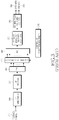
- FIG. 2 illustrates a PUSCH transmitter block diagram.
- Coded CQI bits and/or PMI bits 205 and coded data bits 210 are multiplexed at block 220. If HARQ-ACK bits are also multiplexed, data bits are punctured to accommodate HARQ-ACK bits at block 230. SR information, if any, is included as part of data information.
- IFFT Inverse Fast Fourier Transform
- a CP and filtering are applied to the signal at blocks 270 and 280, respectively, before transmission at block 290.
- additional transmitter circuitry such as digital-to-analog converters, analog filters, amplifiers, and transmitter antennas are not illustrated.
- the PUSCH transmission may occur over clusters of contiguous REs, in accordance with the DFT Spread Orthogonal Frequency Multiple Access (DFT-S-OFDM) principle, which allows signal transmission over one cluster 295A (also known as Single-Carrier Frequency Division Multiple Access (SC-FDMA)), or over multiple clusters 295B.
- DFT-S-OFDM DFT Spread Orthogonal Frequency Multiple Access
- FIG. 3 illustrates the reverse transmitter operations of the transmitter operations illustrated in FIG. 2 .
- RF Radio-Frequency
- FIG. 3 illustrates the reverse transmitter operations of the transmitter operations illustrated in FIG. 2 .
- an antenna receives the Radio-Frequency (RF) analog signal at 310, which may be processed by processing units such as filters, amplifiers, frequency down-converters, and analog-to-digital converters (not illustrated), a digital signal is filtered at block 320 and the CP is removed at block 330.
- RF Radio-Frequency
- FFT Fast Fourier Transform
- IDFT Inverse DFT
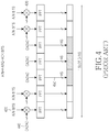
- a structure for the HARQ-ACK signal transmission in the PUCCH in one sub-frame slot is illustrated in FIG. 4 .
- a transmission in the other slot which may be at a different part of the operating BW, may have the same structure as the slot illustrated in FIG. 4 ., or alternatively, as with the PUSCH, the last symbol may be punctured to transmit SRS.
- the PUCCH transmission for each UCI signal is assumed to be within one PRB.
- the HARQ-ACK transmission structure 410 includes the transmission of HARQ-ACK signals and RS.
- the HARQ-ACK bits 420 are modulated, at block 430, according to a "Constant Amplitude Zero Auto-Correlation (CAZAC)" sequence 440, for example with Binary Phase Shift Keying (BPSK) or Quaternary Phase Shift Keying (QPSK) modulation, which is then transmitted after performing the IFFT operation.
- CAZAC Constant Amplitude Zero Auto-Correlation
- BPSK Binary Phase Shift Keying
- QPSK Quaternary Phase Shift Keying
- Each RS 450 is transmitted through the unmodulated CAZAC sequence.
- the CQI transmission structure 510 includes the transmission of CQI signals and RS.
- the CQI bits 520 again are modulated, at block 530, according to a CAZAC sequence 540, for example using QPSK modulation, which is then transmitted after performing the IFFT operation.
- Each RS 550 is again transmitted through the unmodulated CAZAC sequence.
- FIG. 6 shows a transmitter structure for a CAZAC sequence.
- the frequency-domain version of a computer generated CAZAC sequence 610 is described, as an example.
- the REs of the assigned PUCCH PRB are selected at block 620 for mapping, at block 630, the CAZAC sequence
- An IFFT is performed at block 640, and a Cyclic Shift (CS) is applied to the output at block 650.
- CS Cyclic Shift
- a CP and filtering are applied at blocks 660 and 670, respectively, before transmitting the signal at block 680.
- Zero padding is inserted by the reference UE in REs used for the signal transmission by other UEs and in guard REs (not shown).
- additional transmitter circuitry such as digital-to-analog converter, analog filters, amplifiers, and transmitter antennas as they are known in the art, are not shown.
- Reverse (complementary) transmitter operations of the operations illustrated in FIG. 6 are performed for the reception of the CAZAC sequence, as illustrated in FIG. 7 .
- an antenna receives an RF analog signal at block 710.
- processing units such as filters, amplifiers, frequency down-converters, and analog-to-digital converters (not shown)
- the received digital is filtered at block 720 and the CP is removed at block 730.
- the CS is restored at block 740
- a Fast Fourier Transform (FFT) is applied at block 750
- a subcarrier demapping is performed at block 760 to detect the transmitted Res
- the transmitted REs are selected at block 765 based on information from the SA or from higher layer signaling.
- FFT Fast Fourier Transform
- the subsequent correlation 770 with the replica 780 of the CAZAC sequence in order to obtain an estimate of the channel medium (possibly modulated by HARQ-ACK information or CQI information as shown in FIG.4 or FIG.5 , respectively).
- the output 790 is obtained, which can then be passed to a channel estimation unit, such as a time-frequency interpolator, in case of a RS, or can to detect the transmitted information, in case the CAZAC sequence is modulated by HARQ-ACK information or CQI.
- UCI When UCI and data transmission occur in the same sub-frame, UCI may be transmitted together with data in the PUSCH or separately from data in the PUCCH. Including UCI in the PUSCH avoids simultaneous PUSCH and PUCCH transmissions, thereby conserving transmission power and avoiding an increase in the Peak-to-Average Power Ratio (PAPR) or the Cubic Metric (CM) of the combined signal transmission. Conversely, separately transmitting UCI in the PUCCH preserves PUSCH REs for data transmission and utilizes pre-allocated PUCCH resources. The required transmission power can be one of the conditions used to decide whether to simultaneously transmit PUCCH and PUSCH, to transmit UCI with data in the PUSCH, or to even transmit only UCI in the PUCCH and suspend the PUSCH transmission.
- PAPR Peak-to-Average Power Ratio
- CM Cubic Metric
- Transmission Power Control adjusts the PUSCH or PUCCH transmission power to achieve a desired target for the received Signal to Interference and Noise Ratio (SINR) at the Node B, while reducing the interference to neighboring cells and controlling the rise of Interference over Thermal (loT) noise, thereby ensuring the respective reception reliability targets.
- SINR Signal to Interference and Noise Ratio
- LoT Interference over Thermal
- the TPC commands are included either in the SA configuring a dynamic PDSCH reception (TPC command adjusts the subsequent HARQ-ACK signal transmission power) or PUSCH transmission (TPC command adjusts the PUSCH transmission power), or are provided through a channel in the PDCCH carrying TPC commands (TPC channel) for PUSCH or PUCCH transmissions configured to occur periodically.
- a TPC operation is described as follows based on the TPC operation used in 3 rd Generation Partnership Project (3GPP) Evolved- Universal Terrestrial Radio Access (E-UTRA) Long Term Evolution (LTE).
- BWs larger than BWs of a Component Carrier (CC) for legacy systems are needed. These larger BWs can be achieved through the aggregation of multiple legacy CCs. For example, a BW of 60 MHz is achieved by aggregating three 20 MHz CCs.
- a UE may perform multiple PUSCH transmissions during the same sub-frame in the respective UL CCs.
- FIG. 8 illustrates aggregation of multiple legacy CCs, where a UE has three PUSCH transmissions, PUSCH 1 810, PUSCH 2 820 and PUSCH 3 830, in parts of the BW of three respective UL CCs, UC CC1 840, UC CC2 850, and UL CC3 860, during the same sub-frame.
- the TPC operation should therefore be extended to PUSCH transmissions from a UE in multiple UL CCs during the same sub-frame. Additionally, as PUSCH and PUCCH transmissions from a UE in the same sub-frame and in the same or different UL CCs are also supported, the TPC operation should also include the combined operation for the PUSCH TPC and the PUCCH TPC. As a UE may also have multiple PUCCH transmissions in the same sub-frame and in the same or different UL CCs, the PUCCH TPC operation should also include support for multiple PUCCH transmissions. As a UE may have multiple transmitter antennas, the TPC operation should support the signal transmission from multiple antennas.
- LG ELECTRONICS "Uplink multiple channel transmission in case of UE transmit power limitation", 3GPP DRAFT; R1-090655 LTE-A UL TXP LIMITATION, 3RD GENERATION PARTNERSHIP PROJECT (3GPP), MOBILE COMPETENCE CENTRE ; 650, ROUTE DES LUCIOLES ; F-06921 SOPHIA-ANTIPOLIS CEDEX ; FRANCE, no. Athens, Greece; 20090203, 3 February 2009 deals with uplink multiple channel transmission in case of UE transmit power limitation.
- control signaling may be multiplexed with data on a data channel (PUSCH), and control signaling may be transmitted on a control channel (PUCCH) simultaneously with data on a data channel (PUSCH).
- PUSCH data channel
- PUCCH control channel
- the respective transmit powers may be reduced by an equal portion.
- the transmit powers may be reduced by a priority.
- the present invention has been designed to solve at least the aforementioned limitations in the prior art.
- the present invention also provides methods and apparatuses for the TPC application to simultaneous PUSCH transmissions in multiple CCs.
- the present invention is described in relation to an Orthogonal Frequency Division Multiple Access (OFDMA) communication system, the present invention may also be applied to all Frequency Division Multiplexing (FDM) systems generally, including Single-Carrier Frequency Division Multiple Access (SC-FDMA), OFDM, FDMA, Discrete Fourier Transform (DFT)-spread OFDM, DFT-spread OFDMA, SC-OFDMA, and SC-OFDM.
- SC-FDMA Single-Carrier Frequency Division Multiple Access
- DFT Discrete Fourier Transform
- a first aspect of the invention considers a PUSCH TPC operation for multiple PUSCH transmissions from a UE in a sub-frame in the same UL CC and in multiple UL CCs.
- the TPC formula for the PUSCH transmission power in a single CC and over contiguous PRBs also applies, per UL CC, for PUSCH transmission in multiple UL CCs and over contiguous or non-contiguous PRBs.
- Equation (4) is a generalization of the TPC formula for PUSCH transmission in a single UL CC in Equation (1), Equation (4) raises several issues including:
- one option is to reduce the PUSCH transmission power in each UL CC by the same amount so that the total transmission power does not exceed P MAX .
- this reduction option effectively penalizes PUSCH transmissions of higher Spectral Efficiency (SE) more than this reduction option penalizes PUSCH transmissions with lower SE, and therefore, this option is detrimental. Additionally, this reduction option may lead to the suspension of PUSCH transmissions having a low nominal power.
- SE Spectral Efficiency
- the same amount of power reduction may be applied only to PUSCH transmissions in non-contiguous BWs in the same UL CC, which are assumed to have the same SE (or MCS).
- PUSCH transmissions in different UL CCs are allowed to have different SEs (or MCSs) and two approaches are subsequently described herein for adjusting the transmission power when the total UE transmission power exceeds P MAX .
- the same principle applies in each of the two approaches. For some PUSCH transmissions, it is possible to avoid any power reduction while, for the remaining PUSCH transmissions, the adjusted power is proportional to the SINR or to the nominal transmission power.
- the first approach considers that the amount of allocated power is proportional to the SINR of the PUSCH transmission.
- the SE in UL CC k can be expressed as the ratio TBS ( i,k )/ N RE ( i,k ) providing the number of coded information bits per RE.
- SINR i , k 2 TBS i , k N RE i , k ⁇ f ⁇ 1 or, by approximation, SINR i , k ⁇ 2 TBS i , k N RE i , k ⁇ f as the SINR for UEs scheduled PUSCH transmissions in multiple UL CCs is typically sufficiently larger than 1 (in the linear domain).
- a procedure for allocating the power to PUSCH transmissions in multiple UL CCs, when the total nominal transmission power exceeds P MAX includes the following steps:
- the preceding procedure ensures, that in an UL CC where the nominal PUSCH transmission power is lower than the respective transmission power in Equation (6), the nominal PUSCH transmission power is applied according Equation (4) and the sum of nominal PUSCH transmission powers is subtracted from P MAX prior to adjusting the power of PUSCH transmissions in the remaining UL CCs.
- Equation (8) is further refined as Equation (9):
- the procedure can continue from the second sub-step in the same iterative manner with two more sub-sub-steps.
- the mechanisms of the first approach are evident from the preceding description and further details are omitted for clarity and conciseness.
- the UE applies the previous procedure for the PUSCH transmission power allocation in each CC.
- P PUSCH adjust i ,3 ⁇ P PUSCH i ,3 and P PUSCH i ,1 + P PUSCH i ,2 + P PUSCH adjust i ,3 ⁇ P MAX it would be desirable to further increase P PUSCH adjust i ,3 .
- FIG. 9 A PUSCH power allocation using the first approach is illustrated in FIG. 9 .
- the UE first determines the nominal PUSCH transmission power P PUSCH ( i,k ) in each of the UL CCs where the UE has PUSCH transmission in step 910. Subsequently, the UE determines whether the aggregate of the nominal PUSCH transmission powers is less than P MAX in step 920. If the aggregate is less than P MAX is, the PUSCH transmission in an UL CC uses the respective nominal transmission power in step 930.
- the description can be extended in a straightforward manner to include the iterative step but a detailed description thereof is omitted for clarity and conciseness.
- the second approach provides implementation simplicity and similar characteristics as the first approach in the linear range of the Shannon capacity curve and considers that the PUSCH transmission power is proportionally reduced relative to a nominal value according to Equation (10)
- the preceding procedure ensures that in UL CCs where the nominal PUSCH transmission power is less than the respective one in Equation (10), the nominal PUSCH transmission power is applied according to Equation (4) and the sum of nominal PUSCH transmission powers is subtracted from P MAX before adjusting each PUSCH transmission power in the remaining UL CCs.
- the mechanisms of the second approach are evident from the described procedure and further details are omitted for brevity. Additionally, for both the first approach and the second approach, the first step of the power allocation may be avoided in order to simplify the respective procedure (equivalent to the case that the set J is empty).
- FIG. 10 A PUSCH power allocation using the second approach is illustrated in FIG. 10 .
- the UE first determines the nominal PUSCH transmission power P PUSCH ( i,k ) in each respective UL CC in step 1010. Subsequently, the UE determines whether the aggregate of the nominal PUSCH transmission powers is less than P MAX in step 1020. If the aggregate is less than P MAX , the UE transmits its PUSCH in the respective UL CC using the respective nominal transmission power in step 1030.
- the second approach can also be extended in a straightforward manner to include the iterative step. However, a detailed description thereof is omitted for clarity and conciseness. Moreover, detailed description of the iterative step regarding the first approach can be used to show the applicability of the procedure in an iterative fashion according to the second approach.
- a method may also consider that instead of SINRs or nominal transmission powers, the SEs (or the MCSs) can be used as metrics for determining PUSCH transmission power adjustments.
- the SEs or the MCSs
- FIG. 11 Modifications to the PUSCH transmission power allocation according to an embodiment of the present invention are illustrated in FIG. 11 .
- the UE first allocates power to its PUCCH transmissions, if any, over all respective UL CCs including potential multiple PUCCH transmissions in the same UL CC, and to its PUSCH transmissions including UCI, if any.
- the same UCI is not transmitted in both the PUCCH and the PUSCH in sub-frame i .
- the PUSCH transmissions can be ranked in consideration of the presence of UCI, and the ranking can also extend in general to the UL CCs of the PUSCH transmission.
- a UE can be configured by the Node B the UL CCs k ⁇ ⁇ 1, ⁇ ,K ⁇ in order of significance, thereby ranking the UL CCs and having a primary UL CC, a secondary UL CC, etc., or this ranking can be in order of SINR, SE, MCI, or UCI type.
- the value of k now refers to the ranking of the UL CC for a particular UE, but not to the actual physical ordering of an UL CC with respect to the other UL CCs.
- P PUSCH adjust i , K ⁇ 1 is not negative, the PUSCH transmission power adjustment process terminates and the PUSCH in each of the remaining UL CCs k ⁇ ⁇ 1, ⁇ , K -2 ⁇ is allocated the respective nominal transmission power.
- P PUSCH adjust i , K ⁇ 1 is negative, PUSCH transmission in UL CC K -1 is also suspended and the PUSCH transmission power adjustment process continues to UL CC K -2 in the same manner.
- the TPC formula for the PUCCH transmission power from a UE in a single CC and over contiguous PRBs also applies, per UL CC, for PUCCH transmission in multiple UL CCs and over contiguous or non-contiguous PRBs.
- P PUCCH transmission power P PUCCH ( i,k ) from a UE in sub-frame i and UL CC k is set according to Equation (14):
- TPC formula in Equation (10) is a generalization of the TPC formula for a single PUCCH transmission in a single UL CC in Equation (2), the same issues as the issues for PUSCH transmissions in multiple UL CCs are raised including:
- the invention considers the following principles:
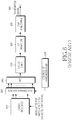
- FIG. 12 A prioritization of power allocation according to an embodiment of the present invention is illustrated in FIG. 12 .
- the existence of HARQ-ACK information for transmission in the reference sub-frame is first determined in step 1210. If there is HARQ-ACK information for transmission either in the PUSCH or in the PUCCH, the respective power is first allocated in step 1212. No reduction in the transmission power is applied unless P MAX is reached, in which case the transmission power of each channel, if more than one, is proportionally reduced as previously described. The allocated power is subtracted from P MAX to obtain a remaining power P MAX rem and, for the subsequent operation of the power allocation procedure, P MAX rem is set to P MAX , in step 1214. If P MAX > 0, or if there is no HARQ-ACK transmission, the power allocation process continues to step 1216; otherwise, the power allocation process ends in step 1218 and no additional channels are transmitted by the reference UE .
- SR information in the reference sub-frame is subsequently determined in step 1220. If there is SR information for transmission either in the PUSCH or in the PUCCH, the respective power is allocated in step 1222. No reduction in the transmission power is applied unless P MAX is reached (in the method according to FIG. 12 it is assumed that SR is transmitted only through one PUCCH or in a PUSCH as part of data information). The allocated power is subtracted from P MAX to obtain a remaining power P MAX rem and, for the subsequent operation of the power allocation procedure, P MAX rem is set to P MAX in step 1224. If P MAX > 0, or if there is no SR transmission, the power allocation process continues in step 1226; otherwise, the power allocation process ends and no additional channels are transmitted by the reference UE in step 1228.
- CQI for transmission in the reference sub-frame is subsequently determined in step 1230. If there is CQI for transmission either in the PUSCH or in the PUCCH, the respective power is allocated in step 1232. No reduction in the transmission power is applied unless P MAX is reached. If it is determined that power reduction is needed in step 1234, the UE determines whether the CQI transmission is CRC protected in step 1236. If the CQI transmission is not CRC protected, the CQI transmission in the PUCCH is dropped in step 1238.
- the allocated power is subtracted from P MAX to obtain a remaining power P MAX rem and, for the subsequent operation of the power allocation procedure, P MAX rem is set to P MAX in step 1240. If P MAX > 0 or if there is no CQI transmission, the power allocation process continues in step 1242; otherwise, the power allocation process ends and no additional channels are transmitted by the reference UE in step 1244.
- the TPC formula for the power of the SRS transmission from a UE in a single CC can also be applied, per UL CC, for SRS transmission in multiple UL CCs.
- the SRS transmission power P SRS ( i,k ) from a UE in sub-frame i and UL CC k is set according to Equation (17)
- Equation (17) is a generalization of the formula in Equation (3).
- P SRS_OFFSET is a UE-specific parameter
- P SRS_OFFSET may be separately configured in each UL CC, since the Power Spectral Density (PSD) of the SRS transmission tracks the PSD of the PUSCH transmission.
- PSD Power Spectral Density
- the parameter P 0_ PUSCH ( k ) can be configured in each UL CC and the SRS transmission BW, as defined by a number of PRBs, can differ among UL CCs (for example, the PUCCH size or SRS multiplexing capacity may differ among UL CCs or the UL CCs may have different BW) and the value of M SRS ( k ) can depend on the UL CC k.
- the TPC operation can be extended to multiple UE transmitter antennas wherein each antenna, m ⁇ ⁇ 1, ⁇ , M ⁇ , has its own Power Amplifier (PA). Since the extensions of the TPC operation for the PUCCH and SRS are straightforward, for clarity and conciseness, the TPC extension operation for only for the PUSCH is described as follows.
- PA Power Amplifier
- Each UE transmitter antenna may have a different class of PA and therefore P MAX may depend on the UE antenna. Furthermore, due to its position, each antenna may experience a different path loss, and therefore a respective measurement is required for each antenna. The remaining parameters in the TPC formula are the same for all antennas.
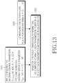
- RRC configures, to a reference UE, the cell-specific parameter ⁇ ( k ) and the parameters P 0, PUSCH ( k ) and K s in UL CC k.
- RRC may also configure, to the UE, the parameter P MAX ( m ) for each UE transmitter antenna m with a separate PA ( m ⁇ ⁇ 1, ⁇ , M ⁇ ) in step 1310.
- the UE measures the DL path-loss PL ( k,m ) for transmitter antenna m in step 1320 and, based on the PUSCH transmission parameters in UL CC k, the UE computes the nominal PUSCH transmission power for transmitter antenna m as in Equation (19) in step 1330.
- FIG. 14 A TPC operation with different CL TPC command per UE transmitter antenna m with a separate PA ( m ⁇ ⁇ 1, ⁇ , M ⁇ ) is illustrated in FIG. 14 .
- RRC configures, to the reference UE, the parameters P 0, PUSCH ( k ), K s and ⁇ ( k ) in UL CC k and the parameter P MAX ( m ) for each UE transmitter antenna m in step 1410.
- the UE measures the DL path-loss PL ( k,m ) for each transmitter antenna m in step 1420.
- the UE receives the CL TPC commands for each transmitter antenna m in the SA configuring the PUSCH transmission parameters (or in a PDCCH TPC channel) in step 1430.
- the UE Based on the PUSCH transmission parameters in UL CC k , the UE computes the nominal PUSCH transmission power for transmitter antenna m as in Equation (20) in step 1440.
Landscapes
- Engineering & Computer Science (AREA)
- Signal Processing (AREA)
- Computer Networks & Wireless Communication (AREA)
- Mobile Radio Communication Systems (AREA)
Priority Applications (1)
| Application Number | Priority Date | Filing Date | Title |
|---|---|---|---|
| PL10754056T PL2409532T3 (pl) | 2009-03-17 | 2010-03-17 | Sterowanie mocą nadawczą łącza wysyłania w systemach łączności o wielu nośnych |
Applications Claiming Priority (2)
| Application Number | Priority Date | Filing Date | Title |
|---|---|---|---|
| US16087909P | 2009-03-17 | 2009-03-17 | |
| PCT/US2010/027653 WO2010107907A2 (en) | 2009-03-17 | 2010-03-17 | Uplink transmission power control in multi-carrier communication systems |
Publications (3)
| Publication Number | Publication Date |
|---|---|
| EP2409532A2 EP2409532A2 (en) | 2012-01-25 |
| EP2409532A4 EP2409532A4 (en) | 2014-12-17 |
| EP2409532B1 true EP2409532B1 (en) | 2018-10-31 |
Family
ID=42740215
Family Applications (1)
| Application Number | Title | Priority Date | Filing Date |
|---|---|---|---|
| EP10754056.9A Active EP2409532B1 (en) | 2009-03-17 | 2010-03-17 | Uplink transmission power control in multi-carrier communication systems |
Country Status (8)
| Country | Link |
|---|---|
| US (3) | US8971299B2 (pl) |
| EP (1) | EP2409532B1 (pl) |
| KR (1) | KR101701262B1 (pl) |
| CN (2) | CN106230567B (pl) |
| AU (1) | AU2010226635B2 (pl) |
| CA (1) | CA2755825C (pl) |
| PL (1) | PL2409532T3 (pl) |
| WO (1) | WO2010107907A2 (pl) |
Families Citing this family (96)
| Publication number | Priority date | Publication date | Assignee | Title |
|---|---|---|---|---|
| KR101587680B1 (ko) | 2008-10-20 | 2016-01-21 | 인터디지탈 패튼 홀딩스, 인크 | 반송파 집적 방법 |
| KR101011988B1 (ko) * | 2009-03-13 | 2011-01-31 | 한국항공대학교산학협력단 | 다양한 개수의 안테나들을 구비하는 사용자 단말들을 포함하는 통신시스템에서 피드백 정보 송수신 방법 및 장치 |
| AR075865A1 (es) | 2009-03-17 | 2011-05-04 | Interdigital Patent Holdings | Metodo y aparato para control de potencia de transmision de senal de referencia de sonido (srs) |
| KR101321036B1 (ko) * | 2009-03-18 | 2013-10-22 | 노키아 지멘스 네트웍스 오와이 | 데이터를 스케쥴링하는 방법 |
| US9401779B2 (en) | 2009-03-29 | 2016-07-26 | Lg Electronics Inc. | Method for transmitting control information in wireless communication system and apparatus therefor |
| CN104581914A (zh) | 2009-04-23 | 2015-04-29 | 交互数字专利控股公司 | 针对多频率使用功率缩放的wtru |
| US8437798B2 (en) * | 2009-04-27 | 2013-05-07 | Motorola Mobility Llc | Uplink scheduling support in multi-carrier wireless communication systems |
| US20100272091A1 (en) * | 2009-04-27 | 2010-10-28 | Motorola, Inc. | Uplink Scheduling Supoort in Multi-Carrier Wireless Communication Systems |
| EP3182775A1 (en) * | 2009-06-17 | 2017-06-21 | IDTP Holdings, Inc. | Scheduling data transmissions between a mobile terminal and a base station in a wireless communications network |
| CN102484869B (zh) * | 2009-06-19 | 2015-09-16 | 交互数字专利控股公司 | 在lte-a中用信号发送上行链路控制信息 |
| US8976729B2 (en) * | 2009-08-19 | 2015-03-10 | Qualcomm Incorporated | Maximum power spectral density reporting in response to overload indications |
| WO2011043394A1 (ja) * | 2009-10-06 | 2011-04-14 | 株式会社エヌ・ティ・ティ・ドコモ | ユーザ装置、基地局装置及び移動通信方法 |
| JP5520003B2 (ja) * | 2009-10-28 | 2014-06-11 | シャープ株式会社 | 無線通信システム、基地局装置、移動局装置、無線通信システムの制御方法、基地局装置の制御プログラムおよび移動局装置の制御プログラム |
| EP2317815A1 (en) | 2009-11-02 | 2011-05-04 | Panasonic Corporation | Power-limit reporting in a communication system using carrier aggregation |
| CN106160992B (zh) | 2010-02-12 | 2020-07-03 | 交互数字专利控股公司 | 增强无线发射/接收单元的小区边缘性能的方法及网络 |
| JP4913222B2 (ja) * | 2010-02-12 | 2012-04-11 | シャープ株式会社 | 無線通信システム、移動局装置、無線通信方法および集積回路 |
| US9042836B2 (en) * | 2010-03-31 | 2015-05-26 | Htc Corporation | Apparatuses and methods for measurement control |
| CN102208967B (zh) * | 2010-03-31 | 2014-04-09 | 中兴通讯股份有限公司 | 一种lte终端非自适应重传功率控制的方法及装置 |
| EP3070872B1 (en) | 2010-04-02 | 2018-06-13 | Interdigital Patent Holdings, Inc. | Uplink sounding reference signals configuration and transmission |
| KR101813031B1 (ko) * | 2010-04-13 | 2017-12-28 | 엘지전자 주식회사 | 상향링크 신호를 전송하는 방법 및 이를 위한 장치 |
| HUE040251T2 (hu) | 2010-04-30 | 2019-02-28 | Sun Patent Trust | Vezeték nélküli kommunikációs eszköz és eljárás adásteljesítmény szabályozására |
| US8948115B2 (en) | 2010-06-16 | 2015-02-03 | Lg Electronics Inc. | Method for controlling uplink transmission power for transmitting a plurality of code words in a wireless communication system that supports a plurality of antennas, and apparatus for performing the method |
| US9002397B2 (en) * | 2010-06-29 | 2015-04-07 | Qualcomm Incorporated | Method and apparatus for device transmit power capping in wireless communications |
| JP4852166B1 (ja) * | 2010-08-04 | 2012-01-11 | シャープ株式会社 | 移動局装置、通信システム、通信方法および集積回路 |
| WO2012020990A2 (ko) * | 2010-08-10 | 2012-02-16 | 엘지전자 주식회사 | 무선 통신 시스템에서 전송 전력 제어 방법 및 장치 |
| KR101788324B1 (ko) | 2010-08-10 | 2017-10-20 | 엘지전자 주식회사 | 무선 통신 시스템에서 전송 전력 제어 방법 및 장치 |
| EP3086608B1 (en) | 2010-08-17 | 2018-10-03 | Google Technology Holdings LLC | Method and apparatus for power headroom reporting during multi-carrier operation |
| US8767596B2 (en) | 2010-08-19 | 2014-07-01 | Motorola Mobility Llc | Method and apparatus for using contention-based resource zones for transmitting data in a wireless network |
| EP2421187B1 (en) * | 2010-08-20 | 2018-02-28 | LG Electronics Inc. | Method for transmitting control information in a wireless communication system and apparatus therefor |
| US9408162B2 (en) * | 2010-09-30 | 2016-08-02 | Qualcomm Incorporated | Power headroom for simultaneous voice and long term evolution |
| US10728859B2 (en) | 2010-10-12 | 2020-07-28 | Samsung Electronics Co., Ltd. | Method and apparatus for determining maximum transmission power per carrier in mobile communication system supporting carrier aggregation |
| WO2012053863A2 (en) | 2010-10-21 | 2012-04-26 | Lg Electronics Inc. | Method and apparatus for transmitting control information in a wireless communication system |
| EP2637332A4 (en) | 2010-11-05 | 2017-11-15 | Samsung Electronics Co., Ltd | Method and device for activating secondary carrier in wireless communication system for using carrier aggregation technique |
| JP5898087B2 (ja) | 2010-11-05 | 2016-04-06 | パナソニック インテレクチュアル プロパティ コーポレーション オブアメリカPanasonic Intellectual Property Corporation of America | 無線通信端末装置及び電力割当方法 |
| US8582518B2 (en) | 2010-11-09 | 2013-11-12 | Telefonaktiebolaget L M Ericsson (Publ) | Power control for ACK/NACK formats with carrier aggregation |
| US9445424B2 (en) * | 2010-11-10 | 2016-09-13 | Telefonaktiebolaget Lm Ericsson (Publ) | Radio base station and method for scheduling radio resources for user equipment |
| US9131450B2 (en) * | 2010-11-16 | 2015-09-08 | Lg Electronics Inc. | Method for controlling uplink transmission power for transmitting a plurality of codewords in a wireless communication system that supports a plurality of antennas, and apparatus for performing the method |
| US8830934B2 (en) * | 2010-12-10 | 2014-09-09 | Qualcomm Incorporated | Configurable filter for multi-radio interference mitigation |
| WO2012081812A1 (ko) * | 2010-12-16 | 2012-06-21 | 엘지전자 주식회사 | 무선 통신 시스템에서 릴레이 노드가 기지국으로 사운딩 참조 신호를 전송하는 방법 및 장치 |
| CN102045827B (zh) * | 2011-01-06 | 2013-07-31 | 大唐移动通信设备有限公司 | 上行功率控制方法、功率控制参数配置方法及其装置 |
| US8908656B2 (en) * | 2011-01-10 | 2014-12-09 | Qualcomm Incorporated | Support for multi-radio coexistence during connection setup |
| US8792376B2 (en) | 2011-01-11 | 2014-07-29 | Samsung Electronics Co., Ltd. | Secondary carrier activation/deactivation method and apparatus for mobile communication system supporting carrier aggregation |
| KR101776873B1 (ko) | 2011-01-11 | 2017-09-11 | 삼성전자 주식회사 | 이동통신 시스템에서 역방향 전송 출력 결정 방법 및 장치 |
| US9578649B2 (en) | 2011-01-20 | 2017-02-21 | Qualcomm Incorporated | Method and apparatus to facilitate support for multi-radio coexistence |
| US20120201158A1 (en) * | 2011-02-03 | 2012-08-09 | Qualcomm Incorporated | Peer-to-peer / wan association control and resource coordination for mobile entities using aggregate neighborhood utility metrics |
| CN103563458B (zh) * | 2011-05-19 | 2017-06-16 | 北京新岸线移动多媒体技术有限公司 | 上行传输开环功率控制方法及装置 |
| EP2538733A1 (en) * | 2011-06-21 | 2012-12-26 | TELEFONAKTIEBOLAGET LM ERICSSON (publ) | Apparatus and method for controlling uplink throughput in a cellular communications system |
| CN102843759B (zh) * | 2011-06-23 | 2016-03-02 | 华为技术有限公司 | 一种上行多入多出信道的功率控制方法和用户设备 |
| WO2013019034A2 (ko) * | 2011-07-29 | 2013-02-07 | 엘지전자 주식회사 | 상향링크 전송 전력을 제어하는 단말 장치 및 그 방법 |
| WO2013025236A1 (en) * | 2011-08-12 | 2013-02-21 | Intel Corporation | System and method of uplink power control in a wireless communication system |
| CN106102150B (zh) * | 2011-08-17 | 2019-08-13 | 华为技术有限公司 | 终端发射上行信号的方法和终端 |
| US9049661B2 (en) | 2011-09-14 | 2015-06-02 | Qualcomm Incorporated | Methods and apparatus to reduce power consumption for HARQ decoding |
| US9295012B2 (en) * | 2011-09-21 | 2016-03-22 | Lg Electronics Inc. | Terminal device for controlling uplink signal transmission power, and method therefor |
| EP2774426B1 (en) * | 2011-11-04 | 2019-01-02 | Interdigital Patent Holdings, Inc. | Method and apparatus for power control for wireless transmissions on multiple component carriers associated with multiple timing advances |
| EP2663137A1 (en) * | 2012-05-10 | 2013-11-13 | Alcatel-Lucent | Uplink transmission power control in MIMO systems |
| GB2502064B (en) * | 2012-05-14 | 2014-04-09 | Broadcom Corp | Power control |
| US9544801B2 (en) | 2012-08-03 | 2017-01-10 | Intel Corporation | Periodic channel state information reporting for coordinated multipoint (coMP) systems |
| JP6632112B2 (ja) * | 2012-08-03 | 2020-01-15 | シャープ株式会社 | 移動局装置、基地局装置、無線通信方法、および集積回路 |
| CN103684722B (zh) * | 2012-09-12 | 2017-07-14 | 中国电信股份有限公司 | 上行探测参考信号的功率分配方法、装置及信号处理系统 |
| CN103874180B (zh) * | 2012-12-14 | 2017-10-31 | 中国电信股份有限公司 | 双路发射终端的最大发射功率控制方法与装置 |
| US10932205B2 (en) * | 2013-08-02 | 2021-02-23 | Blackberry Limited | Uplink power sharing control |
| JP6668242B2 (ja) * | 2013-09-04 | 2020-03-18 | エルジー エレクトロニクス インコーポレイティド | 無線通信システムにおける上りリンク電力を制御する方法及び装置 |
| CN104519561B (zh) * | 2013-09-26 | 2019-02-12 | 中兴通讯股份有限公司 | 上行功率削减处理方法、装置、终端及基站 |
| WO2015069013A1 (ko) * | 2013-11-08 | 2015-05-14 | 주식회사 케이티 | 상향링크 전송 전력을 제어하는 방법과 그 장치 |
| KR101611825B1 (ko) * | 2013-11-08 | 2016-04-14 | 주식회사 케이티 | 상향링크 전송 전력을 제어하는 방법과 그 장치 |
| CN104683082B (zh) * | 2013-12-03 | 2018-10-09 | 索尼公司 | 无线通信系统和在无线通信系统中进行无线通信的方法 |
| US9900844B2 (en) * | 2014-01-13 | 2018-02-20 | Samsung Electronics Co., Ltd. | Uplink transmissions for dual connectivity |
| KR102184585B1 (ko) * | 2014-03-21 | 2020-11-30 | 후아웨이 테크놀러지 컴퍼니 리미티드 | 이중 연결을 고려한 전력 제한 상황에서의 pusch/pucch 전력 스케일링 방법 및 그 장치 |
| KR20160144986A (ko) | 2014-04-09 | 2016-12-19 | 엘지전자 주식회사 | 전력 제어 수행 방법 및 사용자 장치 |
| CN105187177B (zh) * | 2014-06-05 | 2019-10-01 | 中兴通讯股份有限公司 | 数据传输块发送、接收方法及装置 |
| US10959193B2 (en) * | 2014-08-04 | 2021-03-23 | Sharp Kabushiki Kaisha | Terminal device, base station device, and method |
| CN106817760B (zh) * | 2015-11-27 | 2021-11-02 | 中兴通讯股份有限公司 | 功率分配方法及装置 |
| US10172156B2 (en) | 2016-09-12 | 2019-01-01 | Motorola Mobility Llc | Method and apparatus for scheduling uplink transmissions with reduced latency |
| US10412620B2 (en) | 2016-04-01 | 2019-09-10 | Motorola Mobility Llc | Method and apparatus for scheduling uplink transmissions with reduced latency |
| US10542503B2 (en) | 2016-04-01 | 2020-01-21 | Motorola Mobility Llc | Method and apparatus for scheduling uplink transmissions with reduced latency |
| US10117188B2 (en) * | 2016-04-01 | 2018-10-30 | Motorola Mobility Llc | Method and apparatus for scheduling uplink transmissions with reduced latency |
| US10277367B2 (en) | 2016-04-01 | 2019-04-30 | Motorola Mobility Llc | Method and apparatus for scheduling uplink transmissions with reduced latency |
| US10069613B2 (en) | 2016-04-01 | 2018-09-04 | Motorola Mobility Llc | Method and apparatus for scheduling uplink transmissions with reduced latency |
| US10687319B2 (en) * | 2016-08-08 | 2020-06-16 | Comcast Cable Communications, Llc | Group power control for a secondary cell |
| CN109565385B (zh) * | 2016-08-12 | 2021-02-12 | 华为技术有限公司 | 上行信道发送方法和装置 |
| US10772085B2 (en) | 2017-05-04 | 2020-09-08 | Sharp Kabushiki Kaisha | Short PUCCH formats and scheduling request (SR) transmission for 5th generation (5G) new radio access technology (NR) |
| CN109104770B (zh) * | 2017-06-21 | 2021-02-26 | 大唐移动通信设备有限公司 | 一种资源分配方法、装置及基站 |
| US10098136B1 (en) | 2017-06-29 | 2018-10-09 | Amazon Technologies, Inc. | Transmit power and receive gain adjustments in multi-radio devices |
| CN109392072B (zh) * | 2017-08-14 | 2021-08-03 | 普天信息技术有限公司 | 功率余量的计算方法 |
| CN109802820B (zh) | 2017-11-16 | 2023-11-10 | 华为技术有限公司 | 基于序列的信号处理方法及信号处理装置 |
| US11147065B2 (en) * | 2018-01-22 | 2021-10-12 | Qualcomm Incorporated | Feedback bit reservation for uplink control piggybacking |
| US11026180B2 (en) * | 2018-01-23 | 2021-06-01 | Qualcomm Incorporated | Uplink power control configuration |
| CN110113810B (zh) * | 2018-02-01 | 2021-02-26 | 华为技术有限公司 | 一种功率控制方法、相关装置及产品 |
| KR102450969B1 (ko) | 2018-08-09 | 2022-10-05 | 삼성전자 주식회사 | 무선 통신 시스템에서 경로감쇄 결정 방법 및 장치 |
| CN111629429B (zh) * | 2019-02-27 | 2021-09-03 | 华为技术有限公司 | 一种上行功率的调整方法和相关设备 |
| US11284359B2 (en) * | 2019-03-29 | 2022-03-22 | Mediatek Inc. | Uplink power control and time-division multiplexing patterns for dual active protocol stack based handover |
| CN113613322B (zh) * | 2019-08-12 | 2023-06-20 | Oppo广东移动通信有限公司 | 用于确定发射功率的方法和装置 |
| WO2021035457A1 (en) | 2019-08-26 | 2021-03-04 | Qualcomm Incorporated | Full-duplex techniques in wireless communications |
| US20240031940A1 (en) * | 2020-12-09 | 2024-01-25 | Telefonaktiebolaget Lm Ericsson (Publ) | Controlling uplink power level of radio cells |
| US11533688B2 (en) * | 2021-03-17 | 2022-12-20 | T-Mobile Usa, Inc. | Dynamic switching of user equipment power class |
| CN115243353B (zh) * | 2022-06-23 | 2025-07-29 | 中磊电子(苏州)有限公司 | 功率控制方法和相关的基站 |
Family Cites Families (9)
| Publication number | Priority date | Publication date | Assignee | Title |
|---|---|---|---|---|
| EP1216522B1 (en) * | 1999-09-30 | 2007-01-10 | Telefonaktiebolaget LM Ericsson (publ) | Transmit power control |
| EP1274178A1 (en) * | 2001-06-28 | 2003-01-08 | Siemens Information and Communication Networks S.p.A. | Downlink power control in packet switching cellular systems with dynamic channel allocation |
| US7352722B2 (en) * | 2002-05-13 | 2008-04-01 | Qualcomm Incorporated | Mitigation of link imbalance in a wireless communication system |
| EP3515131B1 (en) * | 2004-06-09 | 2023-12-27 | Samsung Electronics Co., Ltd. | Method and apparatus for data transmission in a mobile telecommunication system supporting enhanced uplink service |
| KR20060013466A (ko) * | 2004-08-07 | 2006-02-10 | 삼성전자주식회사 | 소프트 핸드오프 영역에서 역방향 패킷 전송을 위한단말들의 상태 정보 시그널링 방법 |
| KR20060015192A (ko) | 2004-08-13 | 2006-02-16 | 삼성전자주식회사 | 직교 주파수 분할 다중화/직교 주파수 분할 다중 접속통신시스템에서 부반송파의 개별적 송신전력 제어가가능한 폐루프 전력 제어 방법 및 장치 |
| US8345706B2 (en) | 2006-06-19 | 2013-01-01 | Ntt Docomo, Inc. | Base station and method |
| MX2009010279A (es) | 2007-03-30 | 2009-10-13 | Ntt Docomo Inc | Sistema movil de comunicaciones, aparato de estacion base, aparato de usuario y metodo. |
| JP5650668B2 (ja) * | 2009-02-25 | 2015-01-07 | エルジー エレクトロニクス インコーポレイティド | アップリンク伝送における伝送電力を制御する方法及び装置 |
-
2010
- 2010-03-17 US US12/725,847 patent/US8971299B2/en active Active
- 2010-03-17 EP EP10754056.9A patent/EP2409532B1/en active Active
- 2010-03-17 KR KR1020117024451A patent/KR101701262B1/ko active Active
- 2010-03-17 AU AU2010226635A patent/AU2010226635B2/en active Active
- 2010-03-17 PL PL10754056T patent/PL2409532T3/pl unknown
- 2010-03-17 CA CA2755825A patent/CA2755825C/en active Active
- 2010-03-17 WO PCT/US2010/027653 patent/WO2010107907A2/en not_active Ceased
- 2010-03-17 CN CN201610576248.1A patent/CN106230567B/zh active Active
- 2010-03-17 CN CN201080021420.8A patent/CN102428731B/zh active Active
-
2014
- 2014-12-31 US US14/587,461 patent/US9215665B2/en active Active
-
2015
- 2015-09-21 US US14/859,989 patent/US9414323B2/en active Active
Non-Patent Citations (1)
| Title |
|---|
| None * |
Also Published As
| Publication number | Publication date |
|---|---|
| CN102428731B (zh) | 2016-08-24 |
| CN106230567B (zh) | 2019-09-06 |
| EP2409532A2 (en) | 2012-01-25 |
| CN102428731A (zh) | 2012-04-25 |
| CN106230567A (zh) | 2016-12-14 |
| US20150117384A1 (en) | 2015-04-30 |
| WO2010107907A2 (en) | 2010-09-23 |
| US20160014702A1 (en) | 2016-01-14 |
| AU2010226635A1 (en) | 2011-11-10 |
| AU2010226635B2 (en) | 2014-06-12 |
| CA2755825A1 (en) | 2010-09-23 |
| CA2755825C (en) | 2017-04-04 |
| US9215665B2 (en) | 2015-12-15 |
| US8971299B2 (en) | 2015-03-03 |
| KR101701262B1 (ko) | 2017-02-02 |
| US9414323B2 (en) | 2016-08-09 |
| US20100246463A1 (en) | 2010-09-30 |
| PL2409532T3 (pl) | 2019-04-30 |
| EP2409532A4 (en) | 2014-12-17 |
| KR20120003890A (ko) | 2012-01-11 |
| WO2010107907A3 (en) | 2011-01-20 |
Similar Documents
| Publication | Publication Date | Title |
|---|---|---|
| EP2409532B1 (en) | Uplink transmission power control in multi-carrier communication systems | |
| US11929860B2 (en) | Uplink sounding reference signals configuration and transmission | |
| US10404437B2 (en) | PUCCH resource allocation for carrier aggregation in LTE-advanced | |
| CN109565817B (zh) | 针对控制信道的参考数据信道的资源分配 | |
| KR101697903B1 (ko) | 무선통신 시스템에서 사운딩 참조신호의 전송방법 | |
| EP3404963B1 (en) | Transmitting uplink control information over a data channel or over a control channel | |
| EP2086267B1 (en) | Autonomous user equipment transmission power control in communications systems | |
| CN104579604B (zh) | 确认信号传输的索引资源的方法、用户设备及基站 | |
| EP2908579B1 (en) | Methods of providing power headroom reports arranged in order of component carrier indices and related wireless terminals | |
| US8995373B2 (en) | Method for transmitting channel state information in wireless access system | |
| CN116867046A (zh) | 基站、终端、由基站执行的方法及由终端执行的方法 | |
| US20190199468A1 (en) | Dynamic MCS Offset for Short TTI | |
| KR20120134235A (ko) | 기지국의 상향링크 전송 지시 방법 및 단말의 상향링크 전송 방법 |
Legal Events
| Date | Code | Title | Description |
|---|---|---|---|
| PUAI | Public reference made under article 153(3) epc to a published international application that has entered the european phase |
Free format text: ORIGINAL CODE: 0009012 |
|
| 17P | Request for examination filed |
Effective date: 20111017 |
|
| AK | Designated contracting states |
Kind code of ref document: A2 Designated state(s): AT BE BG CH CY CZ DE DK EE ES FI FR GB GR HR HU IE IS IT LI LT LU LV MC MK MT NL NO PL PT RO SE SI SK SM TR |
|
| DAX | Request for extension of the european patent (deleted) | ||
| RAP1 | Party data changed (applicant data changed or rights of an application transferred) |
Owner name: SAMSUNG ELECTRONICS CO., LTD. |
|
| A4 | Supplementary search report drawn up and despatched |
Effective date: 20141117 |
|
| RIC1 | Information provided on ipc code assigned before grant |
Ipc: H04L 5/00 20060101ALI20141111BHEP Ipc: H04W 52/14 20090101ALI20141111BHEP Ipc: H04W 52/24 20090101ALI20141111BHEP Ipc: H04W 52/28 20090101ALI20141111BHEP Ipc: H04W 52/34 20090101ALI20141111BHEP Ipc: H04B 7/06 20060101ALI20141111BHEP Ipc: H04W 52/36 20090101ALI20141111BHEP Ipc: H04W 52/18 20090101ALI20141111BHEP Ipc: H04W 52/30 20090101AFI20141111BHEP Ipc: H04W 52/32 20090101ALI20141111BHEP |
|
| 17Q | First examination report despatched |
Effective date: 20160915 |
|
| STAA | Information on the status of an ep patent application or granted ep patent |
Free format text: STATUS: EXAMINATION IS IN PROGRESS |
|
| REG | Reference to a national code |
Ref country code: DE Ref legal event code: R079 Ref document number: 602010054786 Country of ref document: DE Free format text: PREVIOUS MAIN CLASS: H04W0052300000 Ipc: H04L0027180000 |
|
| GRAP | Despatch of communication of intention to grant a patent |
Free format text: ORIGINAL CODE: EPIDOSNIGR1 |
|
| STAA | Information on the status of an ep patent application or granted ep patent |
Free format text: STATUS: GRANT OF PATENT IS INTENDED |
|
| RIC1 | Information provided on ipc code assigned before grant |
Ipc: H04L 5/00 20060101ALI20180424BHEP Ipc: H04W 52/36 20090101ALI20180424BHEP Ipc: H04L 1/18 20060101ALI20180424BHEP Ipc: H04W 52/34 20090101ALI20180424BHEP Ipc: H04W 52/32 20090101ALI20180424BHEP Ipc: H04L 27/18 20060101AFI20180424BHEP Ipc: H04W 72/04 20090101ALI20180424BHEP Ipc: H04W 52/24 20090101ALI20180424BHEP Ipc: H04W 52/28 20090101ALI20180424BHEP Ipc: H04W 52/18 20090101ALI20180424BHEP Ipc: H04W 52/14 20090101ALI20180424BHEP |
|
| INTG | Intention to grant announced |
Effective date: 20180511 |
|
| GRAS | Grant fee paid |
Free format text: ORIGINAL CODE: EPIDOSNIGR3 |
|
| GRAA | (expected) grant |
Free format text: ORIGINAL CODE: 0009210 |
|
| STAA | Information on the status of an ep patent application or granted ep patent |
Free format text: STATUS: THE PATENT HAS BEEN GRANTED |
|
| AK | Designated contracting states |
Kind code of ref document: B1 Designated state(s): AT BE BG CH CY CZ DE DK EE ES FI FR GB GR HR HU IE IS IT LI LT LU LV MC MK MT NL NO PL PT RO SE SI SK SM TR |
|
| REG | Reference to a national code |
Ref country code: CH Ref legal event code: EP Ref country code: GB Ref legal event code: FG4D |
|
| REG | Reference to a national code |
Ref country code: AT Ref legal event code: REF Ref document number: 1060741 Country of ref document: AT Kind code of ref document: T Effective date: 20181115 |
|
| REG | Reference to a national code |
Ref country code: DE Ref legal event code: R096 Ref document number: 602010054786 Country of ref document: DE |
|
| REG | Reference to a national code |
Ref country code: IE Ref legal event code: FG4D |
|
| REG | Reference to a national code |
Ref country code: SE Ref legal event code: TRGR |
|
| REG | Reference to a national code |
Ref country code: NL Ref legal event code: FP |
|
| REG | Reference to a national code |
Ref country code: LT Ref legal event code: MG4D |
|
| REG | Reference to a national code |
Ref country code: AT Ref legal event code: MK05 Ref document number: 1060741 Country of ref document: AT Kind code of ref document: T Effective date: 20181031 |
|
| PG25 | Lapsed in a contracting state [announced via postgrant information from national office to epo] |
Ref country code: NO Free format text: LAPSE BECAUSE OF FAILURE TO SUBMIT A TRANSLATION OF THE DESCRIPTION OR TO PAY THE FEE WITHIN THE PRESCRIBED TIME-LIMIT Effective date: 20190131 Ref country code: BG Free format text: LAPSE BECAUSE OF FAILURE TO SUBMIT A TRANSLATION OF THE DESCRIPTION OR TO PAY THE FEE WITHIN THE PRESCRIBED TIME-LIMIT Effective date: 20190131 Ref country code: LT Free format text: LAPSE BECAUSE OF FAILURE TO SUBMIT A TRANSLATION OF THE DESCRIPTION OR TO PAY THE FEE WITHIN THE PRESCRIBED TIME-LIMIT Effective date: 20181031 Ref country code: FI Free format text: LAPSE BECAUSE OF FAILURE TO SUBMIT A TRANSLATION OF THE DESCRIPTION OR TO PAY THE FEE WITHIN THE PRESCRIBED TIME-LIMIT Effective date: 20181031 Ref country code: LV Free format text: LAPSE BECAUSE OF FAILURE TO SUBMIT A TRANSLATION OF THE DESCRIPTION OR TO PAY THE FEE WITHIN THE PRESCRIBED TIME-LIMIT Effective date: 20181031 Ref country code: HR Free format text: LAPSE BECAUSE OF FAILURE TO SUBMIT A TRANSLATION OF THE DESCRIPTION OR TO PAY THE FEE WITHIN THE PRESCRIBED TIME-LIMIT Effective date: 20181031 Ref country code: ES Free format text: LAPSE BECAUSE OF FAILURE TO SUBMIT A TRANSLATION OF THE DESCRIPTION OR TO PAY THE FEE WITHIN THE PRESCRIBED TIME-LIMIT Effective date: 20181031 Ref country code: IS Free format text: LAPSE BECAUSE OF FAILURE TO SUBMIT A TRANSLATION OF THE DESCRIPTION OR TO PAY THE FEE WITHIN THE PRESCRIBED TIME-LIMIT Effective date: 20190228 Ref country code: AT Free format text: LAPSE BECAUSE OF FAILURE TO SUBMIT A TRANSLATION OF THE DESCRIPTION OR TO PAY THE FEE WITHIN THE PRESCRIBED TIME-LIMIT Effective date: 20181031 |
|
| PG25 | Lapsed in a contracting state [announced via postgrant information from national office to epo] |
Ref country code: PT Free format text: LAPSE BECAUSE OF FAILURE TO SUBMIT A TRANSLATION OF THE DESCRIPTION OR TO PAY THE FEE WITHIN THE PRESCRIBED TIME-LIMIT Effective date: 20190301 Ref country code: GR Free format text: LAPSE BECAUSE OF FAILURE TO SUBMIT A TRANSLATION OF THE DESCRIPTION OR TO PAY THE FEE WITHIN THE PRESCRIBED TIME-LIMIT Effective date: 20190201 |
|
| PG25 | Lapsed in a contracting state [announced via postgrant information from national office to epo] |
Ref country code: DK Free format text: LAPSE BECAUSE OF FAILURE TO SUBMIT A TRANSLATION OF THE DESCRIPTION OR TO PAY THE FEE WITHIN THE PRESCRIBED TIME-LIMIT Effective date: 20181031 Ref country code: CZ Free format text: LAPSE BECAUSE OF FAILURE TO SUBMIT A TRANSLATION OF THE DESCRIPTION OR TO PAY THE FEE WITHIN THE PRESCRIBED TIME-LIMIT Effective date: 20181031 |
|
| REG | Reference to a national code |
Ref country code: DE Ref legal event code: R097 Ref document number: 602010054786 Country of ref document: DE |
|
| PG25 | Lapsed in a contracting state [announced via postgrant information from national office to epo] |
Ref country code: SK Free format text: LAPSE BECAUSE OF FAILURE TO SUBMIT A TRANSLATION OF THE DESCRIPTION OR TO PAY THE FEE WITHIN THE PRESCRIBED TIME-LIMIT Effective date: 20181031 Ref country code: RO Free format text: LAPSE BECAUSE OF FAILURE TO SUBMIT A TRANSLATION OF THE DESCRIPTION OR TO PAY THE FEE WITHIN THE PRESCRIBED TIME-LIMIT Effective date: 20181031 Ref country code: SM Free format text: LAPSE BECAUSE OF FAILURE TO SUBMIT A TRANSLATION OF THE DESCRIPTION OR TO PAY THE FEE WITHIN THE PRESCRIBED TIME-LIMIT Effective date: 20181031 Ref country code: EE Free format text: LAPSE BECAUSE OF FAILURE TO SUBMIT A TRANSLATION OF THE DESCRIPTION OR TO PAY THE FEE WITHIN THE PRESCRIBED TIME-LIMIT Effective date: 20181031 |
|
| PLBE | No opposition filed within time limit |
Free format text: ORIGINAL CODE: 0009261 |
|
| STAA | Information on the status of an ep patent application or granted ep patent |
Free format text: STATUS: NO OPPOSITION FILED WITHIN TIME LIMIT |
|
| 26N | No opposition filed |
Effective date: 20190801 |
|
| PG25 | Lapsed in a contracting state [announced via postgrant information from national office to epo] |
Ref country code: MC Free format text: LAPSE BECAUSE OF FAILURE TO SUBMIT A TRANSLATION OF THE DESCRIPTION OR TO PAY THE FEE WITHIN THE PRESCRIBED TIME-LIMIT Effective date: 20181031 Ref country code: SI Free format text: LAPSE BECAUSE OF FAILURE TO SUBMIT A TRANSLATION OF THE DESCRIPTION OR TO PAY THE FEE WITHIN THE PRESCRIBED TIME-LIMIT Effective date: 20181031 |
|
| REG | Reference to a national code |
Ref country code: CH Ref legal event code: PL |
|
| PG25 | Lapsed in a contracting state [announced via postgrant information from national office to epo] |
Ref country code: LU Free format text: LAPSE BECAUSE OF NON-PAYMENT OF DUE FEES Effective date: 20190317 |
|
| REG | Reference to a national code |
Ref country code: BE Ref legal event code: MM Effective date: 20190331 |
|
| PG25 | Lapsed in a contracting state [announced via postgrant information from national office to epo] |
Ref country code: LI Free format text: LAPSE BECAUSE OF NON-PAYMENT OF DUE FEES Effective date: 20190331 Ref country code: IE Free format text: LAPSE BECAUSE OF NON-PAYMENT OF DUE FEES Effective date: 20190317 Ref country code: CH Free format text: LAPSE BECAUSE OF NON-PAYMENT OF DUE FEES Effective date: 20190331 |
|
| PG25 | Lapsed in a contracting state [announced via postgrant information from national office to epo] |
Ref country code: BE Free format text: LAPSE BECAUSE OF NON-PAYMENT OF DUE FEES Effective date: 20190331 |
|
| PG25 | Lapsed in a contracting state [announced via postgrant information from national office to epo] |
Ref country code: TR Free format text: LAPSE BECAUSE OF FAILURE TO SUBMIT A TRANSLATION OF THE DESCRIPTION OR TO PAY THE FEE WITHIN THE PRESCRIBED TIME-LIMIT Effective date: 20181031 |
|
| PG25 | Lapsed in a contracting state [announced via postgrant information from national office to epo] |
Ref country code: MT Free format text: LAPSE BECAUSE OF NON-PAYMENT OF DUE FEES Effective date: 20190317 |
|
| PG25 | Lapsed in a contracting state [announced via postgrant information from national office to epo] |
Ref country code: CY Free format text: LAPSE BECAUSE OF FAILURE TO SUBMIT A TRANSLATION OF THE DESCRIPTION OR TO PAY THE FEE WITHIN THE PRESCRIBED TIME-LIMIT Effective date: 20181031 |
|
| PG25 | Lapsed in a contracting state [announced via postgrant information from national office to epo] |
Ref country code: HU Free format text: LAPSE BECAUSE OF FAILURE TO SUBMIT A TRANSLATION OF THE DESCRIPTION OR TO PAY THE FEE WITHIN THE PRESCRIBED TIME-LIMIT; INVALID AB INITIO Effective date: 20100317 |
|
| PG25 | Lapsed in a contracting state [announced via postgrant information from national office to epo] |
Ref country code: MK Free format text: LAPSE BECAUSE OF FAILURE TO SUBMIT A TRANSLATION OF THE DESCRIPTION OR TO PAY THE FEE WITHIN THE PRESCRIBED TIME-LIMIT Effective date: 20181031 |
|
| PGFP | Annual fee paid to national office [announced via postgrant information from national office to epo] |
Ref country code: PL Payment date: 20250221 Year of fee payment: 16 |
|
| PGFP | Annual fee paid to national office [announced via postgrant information from national office to epo] |
Ref country code: NL Payment date: 20260220 Year of fee payment: 17 |
|
| PGFP | Annual fee paid to national office [announced via postgrant information from national office to epo] |
Ref country code: SE Payment date: 20260223 Year of fee payment: 17 |
|
| PGFP | Annual fee paid to national office [announced via postgrant information from national office to epo] |
Ref country code: GB Payment date: 20260224 Year of fee payment: 17 |
|
| PGFP | Annual fee paid to national office [announced via postgrant information from national office to epo] |
Ref country code: DE Payment date: 20260220 Year of fee payment: 17 |
|
| PGFP | Annual fee paid to national office [announced via postgrant information from national office to epo] |
Ref country code: IT Payment date: 20260223 Year of fee payment: 17 |
|
| PGFP | Annual fee paid to national office [announced via postgrant information from national office to epo] |
Ref country code: FR Payment date: 20260224 Year of fee payment: 17 |