EP2409595A1 - Étui amélioré pour lentille de contact - Google Patents
Étui amélioré pour lentille de contact Download PDFInfo
- Publication number
- EP2409595A1 EP2409595A1 EP11174457A EP11174457A EP2409595A1 EP 2409595 A1 EP2409595 A1 EP 2409595A1 EP 11174457 A EP11174457 A EP 11174457A EP 11174457 A EP11174457 A EP 11174457A EP 2409595 A1 EP2409595 A1 EP 2409595A1
- Authority
- EP
- European Patent Office
- Prior art keywords
- stem
- contact lens
- diaphragm
- cap
- lens case
- Prior art date
- Legal status (The legal status is an assumption and is not a legal conclusion. Google has not performed a legal analysis and makes no representation as to the accuracy of the status listed.)
- Granted
Links
Images















Classifications
-
- A—HUMAN NECESSITIES
- A45—HAND OR TRAVELLING ARTICLES
- A45C—PURSES; LUGGAGE; HAND CARRIED BAGS
- A45C11/00—Receptacles for purposes not provided for in groups A45C1/00-A45C9/00
- A45C11/005—Contact lens cases
-
- A—HUMAN NECESSITIES
- A45—HAND OR TRAVELLING ARTICLES
- A45C—PURSES; LUGGAGE; HAND CARRIED BAGS
- A45C13/00—Details; Accessories
- A45C13/005—Hinges
-
- B—PERFORMING OPERATIONS; TRANSPORTING
- B43—WRITING OR DRAWING IMPLEMENTS; BUREAU ACCESSORIES
- B43K—IMPLEMENTS FOR WRITING OR DRAWING
- B43K23/00—Holders or connectors for writing implements; Means for protecting the writing-points
- B43K23/008—Holders comprising finger grips
-
- B—PERFORMING OPERATIONS; TRANSPORTING
- B65—CONVEYING; PACKING; STORING; HANDLING THIN OR FILAMENTARY MATERIAL
- B65D—CONTAINERS FOR STORAGE OR TRANSPORT OF ARTICLES OR MATERIALS, e.g. BAGS, BARRELS, BOTTLES, BOXES, CANS, CARTONS, CRATES, DRUMS, JARS, TANKS, HOPPERS, FORWARDING CONTAINERS; ACCESSORIES, CLOSURES, OR FITTINGS THEREFOR; PACKAGING ELEMENTS; PACKAGES
- B65D2585/00—Containers, packaging elements or packages specially adapted for particular articles or materials
- B65D2585/54—Containers, packaging elements or packages specially adapted for particular articles or materials for articles of special shape not otherwise provided for
- B65D2585/545—Contact lenses
-
- F—MECHANICAL ENGINEERING; LIGHTING; HEATING; WEAPONS; BLASTING
- F16—ENGINEERING ELEMENTS AND UNITS; GENERAL MEASURES FOR PRODUCING AND MAINTAINING EFFECTIVE FUNCTIONING OF MACHINES OR INSTALLATIONS; THERMAL INSULATION IN GENERAL
- F16C—SHAFTS; FLEXIBLE SHAFTS; ELEMENTS OR CRANKSHAFT MECHANISMS; ROTARY BODIES OTHER THAN GEARING ELEMENTS; BEARINGS
- F16C11/00—Pivots; Pivotal connections
- F16C11/04—Pivotal connections
- F16C11/10—Arrangements for locking
-
- Y—GENERAL TAGGING OF NEW TECHNOLOGICAL DEVELOPMENTS; GENERAL TAGGING OF CROSS-SECTIONAL TECHNOLOGIES SPANNING OVER SEVERAL SECTIONS OF THE IPC; TECHNICAL SUBJECTS COVERED BY FORMER USPC CROSS-REFERENCE ART COLLECTIONS [XRACs] AND DIGESTS
- Y10—TECHNICAL SUBJECTS COVERED BY FORMER USPC
- Y10S—TECHNICAL SUBJECTS COVERED BY FORMER USPC CROSS-REFERENCE ART COLLECTIONS [XRACs] AND DIGESTS
- Y10S134/00—Cleaning and liquid contact with solids
- Y10S134/901—Contact lens
Definitions
- the present invention generally relates to contact lens cases.
- U.S. Patent No. 3,770,113 discloses a prior art contact lens storage and disinfection cup system 10.
- the Thomas system is illustrated in FIG. 1 of the present application, and utilizes a planar central stem 12 that engages a cap 13.
- the stem 12 has dome features 14 on each side of the stem 12 and hinged containment cages 16 which pivot into a closed position over the domes 14 and parallel to the planar stem 12.
- Subsequent commercial cup disinfection and storage systems have generally followed the same layout with only minor differences in the ribbing of the cages or the form of the structure used to receive the contact lens. This layout of the lens retaining components has withstood the test of time in part due to the efficiency in which it utilizes space available within the cup.
- dome 14 Users of these lens cases generally find it easier to deliver their lenses to the dome feature 14 instead of the cage 16. This is in part due to the tendency of the damp lens to adhere the dome surface 14 which has more surface area than the cage 16 and more closely resembles the shape of a human eyeball. Since contact lens wearers typically grasp the lens by its convex outer surface to remove it from their eye, the dome 14 provides a ready receptacle without having to change one's grasp on the lens. Contact lens wearers also show preference for larger lens-receiving structures and cages as opposed to smaller ones in which fingers must be more dexterous in order to place or retrieve lenses. This user preference may also be driven by an older population of contact lens wearers who may lack the dexterity of younger lens users.
- Another method to facilitate such reversal would be to reduce the diameter and depth of the lens cage, but this would be judged as user unfriendly by a large portion of lens wearers who find smaller lens cages difficult to use.
- the inner base diameter of commercial contact lens cases range from 0.70 inches to 0.80 inches, and this is what users are accustomed to using.
- the contact lens case configuration 10 disclosed in the '113 patent includes a latching mechanism 20 for holding the hinged members 16 closed in order to retain the lenses.
- the latching mechanism 20 disclosed in the '113 patent consists of latch arms 22 which are disposed on the hinged members 16 and which are configured to engage bottom surfaces 24 of the central stem member 12.
- latches such as that which is disclosed in the '113 patent have a tendency to cut lenses that are not properly aligned when the hinged member is moved into the closed, latched position.
- contact lens cases are made of plastic, using a molding process.
- the molding process used to produce plastic lens cases is generally paced by the speed at which heat can be removed from the molten plastic resin once it has been injected into the mold.
- Plastic resin must be sufficiently cooled and therefore hardened to prevent distortion upon ejection or handling.
- Overly thick sections of plastic slow down the molding process because they require more time to cool. In some instances, thick sections can warp or suffer from surface distortions known as sink, in which the molten plastic within the thick section pulls the hardened outside skin inwards as the molten resin shrinks during cooling.
- An embodiment of the present invention provides an improved contact lens case which includes lens-receiving structures that are provided on hinged members.
- the contact lens case us configured to efficiently utilize space and volume such that no more than 10 cc's of contact lens solution are required to disinfect contact lenses in the case.
- the contact lens case is configured such that it can be easily molded and assembled.
- the contact lens case in accordance with the invention is defined in claim 1.
- FIG. 7 illustrates a contact lens case 40 which is in accordance with an embodiment of the present invention.
- the contact lens case 40 includes a central stem 42 on which is disposed two back-to-back cages 44 (only one of the cages is visible in FIG. 7 , but see also FIGS. 2 , 4 and 6 ).
- the stem 42 is engaged with a cap 46, and a catalyst 48 is engaged with the stem 42 opposite the cap 46.
- the cap 46 engages the top 50 of a cylindrical cup 52, thereby forming an enclosed contact lens case.
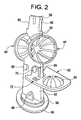
- FIG. 2 shows the stem 42 disengaged from the cap 46.
- the stem 42 is planar and has two, back-to-back cages 44 disposed thereon.
- the cages 44 may be engaged with the stem 42 in a snap-fit arrangement.
- the cages 44 may be integral with the stem 42 (for example, the stem 42 and cages 44 may be a single, plastic molded piece).
- the cages 44 are positioned in back-to-back orientation, with their convex sides 54 facing each other.
- one end 56 of the stem 42 is configured for engagement with the inside of the cap 46, while the opposite, distal end 58 of the stem 42 is configured to receive a catalyst 48.
- indentations 60 may be provided on the stem 42, near its distal end 58, for receiving and retaining a catalyst 48.
- FIG. 3 illustrates one possible shape of the catalyst 48 which can be used, and FIGS. 4 , 5 and 7 illustrate the catalyst 48 engaged with the stem 42. The catalyst will be described in more detail later hereinbelow.
- hinged members 62 are engaged with the stem 42 and each of the hinged members 62 includes a lens-receiving structure 64 such as a solid dome-shaped portion for retaining contact lenses thereon.
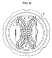
- the hinged members 62 are preferably non-planar (see FIG. 6 which provides a cross-sectional view taken along line 6-6 of FIG.
- each of the hinged members 62 is cylindrically-curved, having a cylindrically-curved shell form in which the axis of its curve is approximately parallel to the central axis of the central planar stem member 42. Specifically, the central axis of each lens cage is disposed parallel to the geometric plane described by the stem 42. Additionally, the central axis of pivoting for each hinged member 62 is perpendicular to the geometric plane described by the stem 42.
- Each hinged member 62 is configured to mount and pivot upon fixed hinge pin receptacles 66 formed upon a common center opposite one another on each side of the planar stem 42.
- Small inward facing pin structures 70 are provided on the hinged members 62 to serve as hinge pins which mount and pivot within the hinge pin receptacles 66 formed on the planar stem 42.
- the cap 46 is generally shaped flat on its top in order to sit stable, inverted on a table surface while lenses are being delivered for disinfection or removed after disinfection.
- the hinged member 62 can be pivoted closed, such that its lens-receiving structure 64 and the respective cage 44 on the stem 42 effectively mate, retaining a contact lens therebetween.
- FIG. 4 shows the stem 42 engaged with the cap 46, a catalyst 48 on the end 58 of the stem 42, and one of the hinged members 62 pivoted down, thereby exposing the lens-receiving structure 64 on the hinged member 62 (and a contact lens, if a contact lens were on the lens-receiving structure 64).
- FIG. 5 shows both hinged members 62 pivoted closed
- FIG. 7 shows both hinged members 62 pivoted closed, and the cap 46 engaged with a cylindrical cup 52.
- each of the hinged members 62 preferably has a right/left indicator 72 ( FIG.
- FIG. 17 shows one of the hinged members 62 including the indicia "L", thereby indicating to the user that that particular hinged member 62 is meant for use with the contact which is placed in the left eye, it should be understood that preferably the other hinged member 62 includes the indicia "R”, thereby indicating to the user that that particular hinged member 62 is meant for use with the contact which is placed in the right eye.
- the fixed hinge elements 62 on the planar stem 42 are cylindrical in nature, each with slot interruptions 74 located 180 degrees from one another in a plane parallel to the center line of the planar stem 42 to allow flushing and drainage and avoid trapping fluid while in an upright or inverted position.
- an internal vent port 99 is provided at the base 98 of the stem 42.
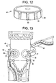
- a second potential hinging mechanism 75 for hinging employs inwardly opposed planar hinge pins 77 upon element 62 that are inserted as shown in FIG. 13 , into cylindrical receptacles 79 provided upon stem 42.
- cylindrical receptacles 79 are positioned perpendicular to the plane of stem 42 and share a common axis with one another on opposite sides of stem 42.
- Receptacles 79 each have aligned receiving slots 85 positioned to allow insertion of opposed hinge pins 77 into an inner cylindrical bore 88.
- FIG. 13 shows how the planar hinge pins 77 of element 62 are inserted into the receiving slots 85.
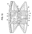
- Assembly of the hinged member 62 utilizes a snap together method with retention of the planar hinge pins 77 being assured by means of the hinge pin retention ledge 87 shown in FIG. 10 .
- Retention ledges 87 result from a gap between tapered ends of opposed hinge pins 77 that is smaller than the width between the bottoms of adjacent receiving slots 85.
- Slots 85 in hinge receptacles 79 provide for drainage of fluid from within each hinge receptacle structure while the small surface area of planar hinge pins 77 remaining in contact with the cylindrical interior of hinge receptacles 79 serve to both facilitate this drainage and minimize fluid retention within the hinge assembly due to capillary attraction.
- latching mechanisms commonly used to hold the hinged members closed in order to retain lenses have often followed the example demonstrated by the Thomas '113 patent. These latches however, have a reputation for cutting misplaced lenses and so it is desirable to utilize a remote latching mechanism.
- One example of such a mechanism is disclosed in U.S. Patent No. 4,807,750 .
- the lens case 40 disclosed herein also utilizes a latch mechanism 76 to hold each hinged member 62 closed and prevent lens damage.
- the latch mechanism 76 may comprise a feature located within each pair of cylindrical hinge receptacles 79 which supports a detent cam surface 81 shown in FIG. 11 , positioned to engage at least one planar hinge pin 77 of each hinged member 62 and thereby hold the hinged member 62 in a closed position.
- the same detent cam 81 is provided for each hinged member 62.
- the latch mechanism 76 also functions to hold the hinged members 62 open. Specifically, as a hinged member 62 is pivoted open, the planar hinge pin tip 83 rides across detent cam surface 81 and seats on the other side of detent cam surface 81.
- the detent cam surface 81 and tip 83 of planar hinge pin 77 are configured such that in either position - whether the hinged member 62 is in the open or closed position - the hinged member 62 tends to stay in that position unless intentionally pivoted by a user.
- each cage 44 and its respective hinged member 62 are preferably curved to match one another (see FIG. 6 ).
- An assembly of the planar central stem 42 with back-to-back lens cages 44 and mating curved hinged members 62 on either side results in a package that does not require as large a cup diameter to accommodate the internal components as would be required if the cages and lens-receiving structures were instead to be provided as having flat faces.
- the case is configured such that use of curved, lens-receiving structure-carrying hinged members 62 allows a desirable lens cage inner base diameter of 0.75 inches to be employed without losing full lens immersion with 10 cc's of lens solution.
- lens-receiving structure 64 an integral, thin-walled and continuous element of the hinged member 62 allows a precise lens-receiving structure form to be quickly molded in a repeatable reliable manner without distortion or sink.
- Lens-receiving structures formed in this manner can be designed to optimize features necessary for preferential retention of lenses during placement and after disinfection or storage.
- the contact lens case 40 disclosed herein utilizes a pressure venting mechanism, such as a vent membrane 80, to relieve excess pressure through a vent notch 103 in the cap 46, as well as a sealing means, such as a sealing gasket 82 portion of the vent membrane 80, at the cap-to-cup interface.
- the cap 46 includes a plug 105 having a post 107 for sealing of the vent notch 103.
- the membrane 80 provides a vent hole 109 in which the post 107 becomes disposed when the cap 46 is screwed on to the top 50 of the cup 52. When venting takes place, the membrane 80 moves away from the post 107 creating a gap, and venting then becomes possible through the vent notch 103 in the cap 46.
- the vent membrane 80 and sealing gasket 82 need not be separate pieces. They can be created simultaneously during the cap's molding process in which, as shown in FIG. 12 , a thermoplastic elastomer 91 is overmolded on the plastic cap structure 46 such that the thermoplastic elastomer 91 becomes effectively integral with the gasket 82 and vent valve 80.
- a thermoplastic elastomer 91 is overmolded on the plastic cap structure 46 such that the thermoplastic elastomer 91 becomes effectively integral with the gasket 82 and vent valve 80.
- an integrally molded cap gasket and elastomeric exterior cap surface are provided, as well as an integrally molded vent mechanism and elastomeric exterior cap surface.
- the thermoplastic elastomer 91 covers the exterior surface of the cap 46 and provides corners 93 to enhance wet grip and tactile feel.
- Contemplated herein also is a redesign of a reaction catalyst that may be attached to the distal end 58 of the planar stem 42.
- Companies such as Bausch and Lomb (easySEPT®), CIBA Vision Corporation (AOSept®) and Sauflon Pharmaceuticals Inc. (OneStep®) each offer Hydrogen Peroxide lens disinfection cup systems having Platinum based catalyst to break down the disinfectant.
- AMO Olysept®
- CIBA Vision Blue Sept®
- Hydrogen Peroxide systems which utilize tablets of catalase enzyme to break down the disinfectant.
- Those systems having the metal-based catalyst all use similar disk like catalytic elements generally cylindrical in form with vertical ribbing and having less height than the diameter of the circle they would fit into.
- the catalyst redesign proposed here, and illustrated in FIG. 3 provides a catalyst 48 which is somewhat elliptical rather than round in form with the short side 84 of the elliptical form aligned with the hinged members 62 (see FIG. 4 ), and the long side 86 of the elliptical form being perpendicular to the hinged members 62. This orientation helps assure that the catalyst 48 does not inhibit user access to the lens-receiving structures 64. Height of this reconfigured catalyst would not be appreciably different from existing catalysts in the market place, the amount of active surface area and its orientation being the most important factors in determining final catalyst design.
- contact lens case 40 may include, but may not be limited to:
- FIGS. 15-18 illustrate a contact lens case 140 which is in accordance with a preferred embodiment of the present invention.
- the contact lens case 140 is very similar to the contact lens case 40 previously described, and so only the differences will be discussed in detail.
- the contact lens case 140 includes a stem 142 that has back-to-back cages 144 thereon, hinged members 162 that have lens-receiving structures 164 thereon, and a cup 152.
- the contact lens case 140 also includes a cap 146 which is part of a cap assembly (described in more detail later hereinbelow), and which engages the top 150 of the cylindrical cup 152, such as in a threaded engagement, thereby providing that the lens case 140 is an enclosed structure.
- a catalyst is engaged with the stem 142 opposite the cap 146, and the catalyst may be a conventional catalyst or a catalyst 48 such as is shown in FIG. 3 and which has been described hereinabove.
- the stem 142 of lens case 140 has two, back-to-back cages 144 disposed thereon.
- the cages 144 may be engaged with the stem 142 in a snap-fit arrangement.
- the cages 144 may be integral with the stem 142 (for example, the stem 142 and cages 144 may be a single, plastic molded piece as shown in the figures). Regardless, preferably the cages 144 are positioned in back-to-back orientation, with their convex sides 154 facing each other.
- one end 156 of the stem 142 is configured for engagement with the inside 157 of the cap assembly 146.
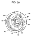
- the end 156 of the stem 142 may provide a square-like shape profile which inserts in a corresponding recess 159 defined by an extended square wall 177 on the inside surface 157 of the cap assembly 146.
- the end 156 of the stem 142 may provide a plurality of protrusions 161 which insert in corresponding apertures 163 formed in the square wall 177 on the inside surface 157 of the cap assembly 146, in a snap-fit engagement.
- the opposite, distal end 158 of the stem 142 is configured to receive the catalyst 48.
- fingers 165 having indentations 160 may be provided on the stem 142, near its distal end 158, for receiving and retaining the catalyst 48.
- hinged members 162 are engaged with the stem 142 and each of the hinged members 162 includes a lens-receiving structure 164 such as a dome-shaped portion for retaining contact lenses thereon.
- the hinged members 162 are preferably non-planar (see FIGS.
- Each of the hinged members 162 is cylindrically-curved, having a cylindrically-curved shell form in which the axis of its curve is approximately parallel to the central axis of the central planar stem member 142. Specifically, the central axis of each lens cage is disposed parallel to the geometric plane described by the stem 142. Additionally, the central axis of pivoting for each hinged member 162 is perpendicular to the geometric plane described by the stem.
- Each hinged member 162 is configured to mount and pivot within fixed hinge pin receptacles 179 which are provided upon a common center opposite one another on each side of the stem 142.
- small inward facing pin structures 177 are provided on support ears 205 of the hinged members 162, and these pin structures 177 mount and rotate within the hinge pin receptacles 179 formed on the stem 142 as the hinged members 162 are being opened and closed.
- the cylindrical receptacles 179 are positioned perpendicular to the plane of stem 142 and share a common axis with one another on opposite sides of stem 142.
- the receptacles 179 each have aligned receiving slots 185 positioned to allow insertion of the hinge pins 177 into an inner cylindrical bore 188 in the receptacles 179.
- the hinge pins 177 are configured to snap into the pin receptacles 179.
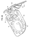
- the hinge pins 177 of the contact lens case 140 have been rotated 90 degrees (compare pin 77 as shown in FIG. 14 to pin 177 as shown in FIG. 28 ) on their common axis such that when the hinged members 162 are installed, they are already in the natural closed position (as shown in FIGS. 15-18 ). This saves time during assembly and simplifies the process by eliminating any requirement to subsequently fold the hinged members 162 into their closed position after installation.
- This planar hinge pin orientation also serves to add extra resistance beyond the snap in feature against a hinged member 162 being accidentally pulled from its socket 179 while in an open position, since the planar hinge pin 177 is traverse to its receiving receptacle 179 instead of being in line with it.
- the lens-receiving structure 164 of the hinged member 162 becomes exposed, ready to receive a contact lens.
- the cap assembly 146 of lens case 140 is generally shaped flat on its top in order to sit stable, inverted on a table surface while lenses are being delivered for disinfection or removed after disinfection.
- the hinged member 162 can be pivoted closed, such that its lens-receiving structure 164 and the respective cage 144 on the stem 142 effectively mate, retaining a contact lens therebetween.
- each of the hinged members 162 preferably has a right/left indicator 172, so that a user knows which contact lens is supposed to be engaged with that particular lens-receiving structure.
- each hinged member 162 not only has a pin 177 but also cam followers 191 which are provided transverse to each planar hinge pin 177.
- the cam followers 191 provide a cam action with regard to a hinge pin cam surface 181 which is on the face 167 of each cylindrical receptacle 179.
- the cam surface 181 of the lens case 140 is provided on the cylindrical face 167 of each cylindrical receptacle 179, thereby positioning each feature further from each hinge pin's rotational axis 169 (see FIG. 19 ). This allows more tolerance for variation of both the cam followers 191 and the hinge pin cam surface 181. Moving further from the rotational axis also provides better mechanical advantage for interacting detenting elements to retain hinged members 162 in both open and closed positions.
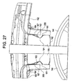
- Each hinge pin cam surface 181 consists of a plurality of "V"-shaped cam notches 183, including a “hold open” cam notch 201 and “hold closed” ramps 203. As a hinged member 162 is pivoted open, the cam surfaces 191 ride across the "hold closed” ramps 203 into the "hold open” cam notch 201 (see FIGS. 27 and 35 ). Regardless of whether the hinged member 162 is in the open or closed position, the hinged member 162 tends to stay in that position unless intentionally pivoted by a user.
- the hinged members 162 may be held open by engaging a simple matching "V" shaped cam notch 201 (as previously described) appropriately positioned on the cylindrical receptacle's end face 167.
- a mechanism that automatically urges each hinged member 162 into a position snuggly abutting the stem 142, preferably with a small amount of sustained spring force such that looseness or gapping between stem 142 and hinged member 162 is prevented when closed.
- Each of the four cam followers 191 provided transverse to adjoining planar hinge pins 177 engages one of four appropriately placed closing cams provided on surface 181, thereby keeping torque loads balanced and preventing undesirable sustained twisting loads against the hinge pin support ears 205.
- each hold closed cam is equipped with a hold closed ramp 203 having extra travel allowance to assure sustained closure force, the deepest points of the hold open and hold closed cams are positioned greater than 90 degrees relative to one another.
- the cam followers 191 sit on the ramps 203 rather than in the notch 201 (i.e., in the lowest point of the cam).
- the hinge pin supporting ears 205 are preferably specifically designed for flexing in order to prevent an over-stressed condition leading to fracture, it is necessary to take care that the location and timing of the hold closed cam ramps 203 are such that only minimum sustained outward deflection is applied to the supporting ears 205 while in a closed position.
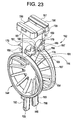
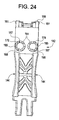
- the hinged elements 162 on the planar stem 142 are preferably cylindrical in nature, each with slot interruptions 174 (see FIGS. 19 , 20 , 26 and 28 ) located 180 degrees from one another in a plane perpendicular to the center line of the planar stem 142 to allow flushing and drainage and avoid trapping fluid while in an upright or inverted position. Additionally, as shown in FIG. 23 , preferably a top surface of the stem 142 is shaped such that it provides internal vent ports 199.
- each cage 144 and its respective hinged members 162 are curved to match one another.
- An assembly of the planar central stem 142 with back-to-back lens cages 144 and mating curved hinged members 162 on either side results in a package that does not require as large a cup diameter to accommodate the internal components as would be required if the cages and lens-receiving structures were instead to be provided as having flat faces.
- the case is configured such that use of curved, lens-receiving structure-carrying hinged members 162 allows a desirable lens cage inner base diameter of 0.75 inches to be employed without losing full lens immersion with 10 cc's of lens solution.
- lens-receiving structure 164 an integral, thin-walled and continuous element of the hinged member 162 allows a precise lens-receiving structure form to be quickly molded in a repeatable reliable manner without distortion or sink.
- Lens-receiving structures formed in this manner can be designed to optimize features necessary for preferential retention of lenses during placement and after disinfection or storage.
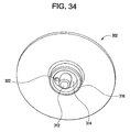
- FIGS. 31 and 32 Other components of the contact lens case 140 include a sealing gasket 300 (shown in FIGS. 31 and 32 ) with an integrally formed vent hole 308 and a plug 302 (shown in FIGS. 33 and 34 ).
- the sealing gasket 300 is molded in place, fused within the cap 146. As such, the gasket 300 does not exist as a separate component, separate from the cap 146. Nevertheless, for clarity with regard to understanding the shape of the gasket 300, the gasket 300 is shown alone in FIGS. 31 and 32 ). While the gasket 300 is fused in place within the cap 146 when it is molded in place, the plug 302 is configured to engage the gasket 300 such that the three components, when assembled, provide an overall cap assembly (a cross-sectional view of which is shown in FIG.
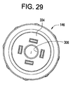
- the cap 146 has a flat top surface 305 (for resting on a tabletop or counter), a threaded surface 304 for threadably engaging the top 150 of the cup 152, and a venting feature which will be described in more detail later hereinbelow.
- the cap 146 includes a center hole 306 as shown in FIGS. 29 and 30 .
- the gasket 300 includes four extending walls 309, and the walls 309 are formed in the apertures 163 in the cap 146 when the gasket 300 is molded and fused in place to the inside surface 157 of the cap 146. As these walls 309 are made out of elastomeric material, they compress and deflect out of the way of protrusions 161 (see FIG. 23 ) to allow a snap fit engagement.
- the gasket 300 also has a center vent hole 308, and openings 310 which are formed between the four extending walls 309. As shown in FIG.
- the plug 302 includes a stem 312 on its inner surface 314, and this stem 312 inserts in the center hole 306 of the cap 146 and in the center vent hole 308 of the gasket 300.
- a circular wall 316 Surrounding the stem 312 of the plug 302 is a circular wall 316, and this circular wall 316 extends through the center hole 306 of the cap 146 and seats against a corresponding circular wall 318 which is provided on the top 320 of the gasket 300 as shown in FIG. 31 .
- a vent hole 322 is provided on the plug 302, disposed in an area between the stem 312 and the circular wall 316, to provide a venting feature.
- the plug 302 When assembled, the plug 302 seats in a recessed seat 334 which is provided on the cap 146, and the pin 312 extends through the center vent hole 308 in the gasket 300.
- FIGS. 37 and 38 illustrate yet another embodiment of the present invention.
- FIGS. 37 and 38 illustrate a contact lens case 500 which includes a member or diaphragm 502, such as an elastomeric member, which is disposed between the cap 504 and the stem 506.
- the diaphragm 502 effectively amounts to a combination gasket and vent component, because the diaphragm 502 not only seals with a top edge 508 of the cup 510 when the cap 504 is engaged with the cup 510, but the diaphragm 502 also includes a dome portion 512 that has a vent slit or notch 514 which is configured to open once the inside 516 of the cup 504 reaches a sufficient enough pressure, in order to vent the contact lens case 500.
- the diaphragm 502 preferably engages both the stem 506 and the cap 504 in a snap fit arrangement. Specifically, the diaphragm 502 is configured to snap onto the stem 506 and then snap into the underside 518 of the cap 504. In this manner, the diaphragm 502 not only provides gasket and venting features, but also functions to effectively secure the cap 504 and stem 506 together.
- the diaphragm 502 includes a stem-receiving pocket 520 and the top portion 522 of the stem 506 includes an upwardly extending member 524 which provides a circumferential shoulder 526 (see FIG. 39 ).
- An undercut 528 of the diaphragm 502 (see FIGS. 37 , 38 and 40 ) clears and engages under the shoulder 526, thereby providing that the diaphragm 502 is retained on the top portion 522 of the stem 506 in a snap fit arrangement.
- the diaphragm 502 also includes a lip 530 around the dome portion 512 (see FIGS. 37 , 38 and 41 ) which is configured to receive fingers 532 (see FIG.
- the stem 506 remains effectively secured to the cap 504 (via diaphragm 502) as the cap 504 is removed.
- the underside 518 of the cap 504 also includes structure 534, such as slotted depending cylinder segments, which is configured to arrest the diaphragm's upward excursion when the diaphragm 502 balloons under pressure.
- structure 534 such as slotted depending cylinder segments, which is configured to arrest the diaphragm's upward excursion when the diaphragm 502 balloons under pressure.
- Proximate the fingers 532 are openings 536 in the cap 504 through which the contact lens case 500 ultimately vents when the slit 514 in the diaphragm 502 opens under pressure.
- the top portion 522 of the stem 506 also includes passageways 537 which allow gas in the cup 510 to travel through the passageways 537 and exert pressure on the dome portion 512 of the diaphragm 502.
- the dome 512 rises and contacts the depending cylinder segments 534 on the underside 518 of the cap 504 which first arrest the dome's movement and "ballooning" from internal pressure, and cause the level of pressure required to initiate venting to rise until tension from additional pressure forces the gas to escape through the notch 514 and a gap 538 between the depending cylindrical segments 534 and channel 535, and out the openings 536.
- Controlling the diaphragm's excursion in this manner also restricts how large the notch 514 can open and thus limits the rate of flow from the cup 510.
- peak pressure can easily be controlled to anywhere up to 50 psi and possibly beyond.
- Elastomeric membranes having punctures to allow release of internal pressure from within a contact lens case have been utilized in prior art as shown by Iba in US Patent 5,143,104 .
- this type of venting system offers little in the way of resistance to conditions in which external pressure exceeded internal pressure such as might occur if a lens case was carried in an airplane when it landed and was therefore subjected to elevated ambient pressure. Under such conditions where elevated external pressure overcomes the vent to equalize internal pressure, reverse air flow through the vent can drive foreign matter and pathogens into the lens case and contaminate lenses stored inside.
- Kanner in US Patent 5, 250,266 solves this problem by providing a supporting seat behind the slit elastomeric membrane to create a one way valve which prevents the slit from inverting under reverse pressure conditions and therefore stops external flow into the lens case.
- Vent notch 514 in domed portion 512 of diaphragm 502 prevents undesirable reverse flow without requiring provision of an additional supporting seat structure.
- domed portion 512 responds by forcing vent notch 514 tightly together as deflection of the domed shape in reaction to the external pressure is resisted by the circumferential constraint and support provided by receiving fmgers 532 of cap 504. Therefore, as external pressure increases, compression upon vent notch 514 also increases thereby increasing its ability to resist reverse flow and intrusion of foreign matter or pathogens.
- FIG. 39 illustrates the situation where the lower portion 540 of the stem 506 is provided as being a variation of that of the stems 42, 142 of the contact lens cases 40, 140 previously described.
- the lower portion 540 of the stem 506 can be provided as having relatively flattened back-to-back cages 542, wherein each cage 542 includes a lens-receiving button 544 and openings 545 to allow the passage of solution.
- the stem 506 can be provided as having a modified end portion 546 (see FIG.
- the end portion 546 of the stem 506 can be provided as being consistent with that which is disclosed in U.S. Patent No. 6,148,992 , which is hereby incorporated herein by reference in its entirety, and therefore having structure such as notches 561 for retaining a catalyst.
- the receptacles 550 on the stem 506 are identical to the receptacles 179 which are shown in FIG. 23 and which have been previously described.
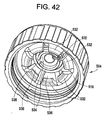
- FIG. 43 provides an exemplary illustration of a possible hinged member configuration 550 which can be used with such a stem 506, where the other hinged member 552 (see FIGS. 37 and 38 ) would be effectively the same but provided for the left contact lens.
- each hinged member 550, 552 may include a dome 554 which curves outward, generally away from the lens-receiving button 544 on the stem 506 (rather than being curved inward as in the embodiments previously described), and which includes openings 556 for passage of solution.
- the hinged members 550, 552 include pins 558 and cam followers 560 identical to the pins 177 and cam followers 191 shown in FIG. 20 and function the same way with regard to the receptacles 550 on the stem 506.
- the configuration of the lower portion 540 of the stem 506 shown in FIG. 39 and the configuration of the hinged members 550, 552 shown in FIGS. 37 , 38 and 43 can be employed with any of the embodiments previously described, and need not necessarily be employed with the diaphragm 502 shown in FIGS. 37-40 and described hereinabove.
Landscapes
- Purses, Travelling Bags, Baskets, Or Suitcases (AREA)
- Apparatus For Disinfection Or Sterilisation (AREA)
- Eyeglasses (AREA)
Priority Applications (1)
| Application Number | Priority Date | Filing Date | Title |
|---|---|---|---|
| PL11174457T PL2409595T3 (pl) | 2010-07-21 | 2011-07-19 | Ulepszony pojemnik na soczewki kontaktowe |
Applications Claiming Priority (2)
| Application Number | Priority Date | Filing Date | Title |
|---|---|---|---|
| US36644510P | 2010-07-21 | 2010-07-21 | |
| US12/944,478 US8141699B2 (en) | 2008-02-07 | 2010-11-11 | Contact lens case |
Publications (2)
| Publication Number | Publication Date |
|---|---|
| EP2409595A1 true EP2409595A1 (fr) | 2012-01-25 |
| EP2409595B1 EP2409595B1 (fr) | 2013-08-28 |
Family
ID=43779105
Family Applications (1)
| Application Number | Title | Priority Date | Filing Date |
|---|---|---|---|
| EP11174457.9A Active EP2409595B1 (fr) | 2010-07-21 | 2011-07-19 | Étui amélioré pour lentille de contact |
Country Status (4)
| Country | Link |
|---|---|
| US (1) | US8141699B2 (fr) |
| EP (1) | EP2409595B1 (fr) |
| ES (1) | ES2431077T3 (fr) |
| PL (1) | PL2409595T3 (fr) |
Cited By (1)
| Publication number | Priority date | Publication date | Assignee | Title |
|---|---|---|---|---|
| JP2018068871A (ja) * | 2016-11-02 | 2018-05-10 | 株式会社トーメーポート | ソフトコンタクトレンズ用収納ケース |
Families Citing this family (11)
| Publication number | Priority date | Publication date | Assignee | Title |
|---|---|---|---|---|
| USD753390S1 (en) * | 2012-01-18 | 2016-04-12 | Atrion Medical Products, Inc. | Contact lens case |
| USD714548S1 (en) * | 2012-10-25 | 2014-10-07 | Atrion Medical Products, Inc. | Contact lens case |
| US9532632B2 (en) | 2015-05-08 | 2017-01-03 | Better Vision Solutions LLC | Pressure-venting container for disinfection and storage of contact lenses |
| USD912982S1 (en) * | 2019-05-28 | 2021-03-16 | Da-Young Kim | Storage container for contact lens |
| USD913692S1 (en) * | 2019-05-28 | 2021-03-23 | Da-Young Kim | Storage case for contact lens container |
| USD965971S1 (en) | 2019-05-28 | 2022-10-11 | Da-Young Kim | Storage container for contact lens |
| USD965972S1 (en) | 2019-05-28 | 2022-10-11 | Da-Young Kim | Storage container for contact lens |
| USD908354S1 (en) * | 2019-05-28 | 2021-01-26 | Da-Young Kim | Storage case for contact lens container |
| USD912981S1 (en) * | 2019-05-28 | 2021-03-16 | Da-Young Kim | Storage container for contact lens |
| USD908355S1 (en) * | 2019-05-28 | 2021-01-26 | Da-Young Kim | Storage case for contact lens container |
| TWI910927B (zh) * | 2024-11-22 | 2026-01-01 | 均賀科技股份有限公司 | 防溢隱形眼鏡容器 |
Citations (11)
| Publication number | Priority date | Publication date | Assignee | Title |
|---|---|---|---|---|
| US3770113A (en) | 1972-03-03 | 1973-11-06 | Mcd Corp | Contact lens holder |
| US4750610A (en) * | 1986-12-29 | 1988-06-14 | Ryder International Corporation | Lens case with pressure sensitive venting system |
| US4807750A (en) | 1987-10-28 | 1989-02-28 | Ryder International Corporation | Latching structure for contact lens holder |
| EP0354876A1 (fr) * | 1988-08-12 | 1990-02-14 | Ciba-Geigy Ag | Elément de désinfection pour lentilles de contact |
| US4956156A (en) | 1988-11-07 | 1990-09-11 | Ryder International Corporation | Pressure venting system for lens cases |
| WO1992009942A1 (fr) * | 1990-11-30 | 1992-06-11 | Ciba Vision Corporation | Systeme de mise a l'air de flacon pour lentilles de contact |
| US5143104A (en) | 1990-12-07 | 1992-09-01 | Allergan, Inc. | Vented apparatus for storing and cleaning an element |
| US5250266A (en) | 1990-11-30 | 1993-10-05 | Ciba Vision Corporation | Contact lens case venting system |
| US5292488A (en) * | 1989-06-09 | 1994-03-08 | Ciba Vision Corporation | Catalyst support assembly for a contact lens sterilizing apparatus |
| US6148992A (en) | 1993-02-02 | 2000-11-21 | Atrion Medical Products, Inc. | Lens case for contact lens disinfecting |
| US20080185298A1 (en) * | 2007-02-07 | 2008-08-07 | Atrion Medical Products, Inc. | Contact lens case |
Family Cites Families (25)
| Publication number | Priority date | Publication date | Assignee | Title |
|---|---|---|---|---|
| US4011941A (en) | 1975-04-28 | 1977-03-15 | Warner-Lambert Company | Contact lens capsule |
| US4013410A (en) | 1975-06-23 | 1977-03-22 | Ryder International Corporation | Contact lens sterilization process and apparatus |
| US4009777A (en) | 1975-12-29 | 1977-03-01 | Ryder International Corporation | Contact lens holder |
| US4200187A (en) | 1978-10-27 | 1980-04-29 | Ryder International Corporation | Lens case with oppositely hinged baskets |
| US4396583A (en) * | 1981-08-14 | 1983-08-02 | American Optical Corporation | Device for single solution contact lens sterilization |
| US4637919A (en) | 1984-11-05 | 1987-01-20 | Ryder International Corporation | Lens disinfecting appliance with improved venting feature |
| US4817998A (en) | 1987-08-03 | 1989-04-04 | Ryder International Corporation | Instrument for handling contact lens disinfecting catalyst |
| US4889693A (en) | 1988-01-22 | 1989-12-26 | Ciba-Geigy Corporation | Apparatus for venting of gases from contact lens cases |
| US4981657A (en) | 1988-09-09 | 1991-01-01 | Ryder International Corporation | Contact lens case with raised, protective ribs |
| US4996027A (en) | 1989-04-07 | 1991-02-26 | Ciba Vision Corporation | Contact lens case having pressure venting gasket |
| US4890729A (en) | 1989-04-25 | 1990-01-02 | Ryder International Corporation | Lens retaining apparatus |
| US5468448A (en) | 1989-12-28 | 1995-11-21 | Ciba-Geigy Corporation | Peroxide disinfection method and devices therefor |
| US5306352A (en) | 1989-12-28 | 1994-04-26 | Ciba-Geigy Corporation | Peroxide disinfection method |
| WO1992004921A1 (fr) * | 1990-09-25 | 1992-04-02 | Allergan, Inc. | Appareil et procede de desinfection d'une lentille de contact et de detection de la presence d'un desinfectant oxydant |
| US5186317A (en) * | 1992-02-04 | 1993-02-16 | Ryder International Corporation | Lens case for contact lens disinfecting system |
| DK168746B1 (da) | 1992-07-06 | 1994-05-30 | Tom Buris Nielsen | Fremgangsmåde og etui til desinficering af kontaktlinser |
| US5366078A (en) | 1993-09-28 | 1994-11-22 | Bausch & Lomb Incorporated | Vented carrying case for contact lenses |
| US5690211A (en) | 1994-11-07 | 1997-11-25 | Jao; Shu-Wen | Contact lens cleaner |
| US5558846A (en) | 1994-12-05 | 1996-09-24 | Ciba Geigy Corporation | Apparatus for disinfecting contact lenses having improved vent means |
| US5609837A (en) | 1995-08-16 | 1997-03-11 | Cerny; David E. | Disinfection apparatus |
| US6364098B2 (en) | 1999-04-09 | 2002-04-02 | Third Millenium Trust | Soft contact lens cleaning and storage system |
| TWI226227B (en) * | 2001-07-10 | 2005-01-11 | Novartis Ag | Contact lens container |
| US7540376B2 (en) | 2003-10-22 | 2009-06-02 | Novartis Ag | Contact lens case |
| US7178666B2 (en) | 2004-05-25 | 2007-02-20 | Joey Huang | Contact lens holder |
| US20060102496A1 (en) | 2004-11-12 | 2006-05-18 | Bruce Christy | Contact lens case having a lid with soft gripping surface |
-
2010
- 2010-11-11 US US12/944,478 patent/US8141699B2/en active Active
-
2011
- 2011-07-19 PL PL11174457T patent/PL2409595T3/pl unknown
- 2011-07-19 EP EP11174457.9A patent/EP2409595B1/fr active Active
- 2011-07-19 ES ES11174457T patent/ES2431077T3/es active Active
Patent Citations (11)
| Publication number | Priority date | Publication date | Assignee | Title |
|---|---|---|---|---|
| US3770113A (en) | 1972-03-03 | 1973-11-06 | Mcd Corp | Contact lens holder |
| US4750610A (en) * | 1986-12-29 | 1988-06-14 | Ryder International Corporation | Lens case with pressure sensitive venting system |
| US4807750A (en) | 1987-10-28 | 1989-02-28 | Ryder International Corporation | Latching structure for contact lens holder |
| EP0354876A1 (fr) * | 1988-08-12 | 1990-02-14 | Ciba-Geigy Ag | Elément de désinfection pour lentilles de contact |
| US4956156A (en) | 1988-11-07 | 1990-09-11 | Ryder International Corporation | Pressure venting system for lens cases |
| US5292488A (en) * | 1989-06-09 | 1994-03-08 | Ciba Vision Corporation | Catalyst support assembly for a contact lens sterilizing apparatus |
| WO1992009942A1 (fr) * | 1990-11-30 | 1992-06-11 | Ciba Vision Corporation | Systeme de mise a l'air de flacon pour lentilles de contact |
| US5250266A (en) | 1990-11-30 | 1993-10-05 | Ciba Vision Corporation | Contact lens case venting system |
| US5143104A (en) | 1990-12-07 | 1992-09-01 | Allergan, Inc. | Vented apparatus for storing and cleaning an element |
| US6148992A (en) | 1993-02-02 | 2000-11-21 | Atrion Medical Products, Inc. | Lens case for contact lens disinfecting |
| US20080185298A1 (en) * | 2007-02-07 | 2008-08-07 | Atrion Medical Products, Inc. | Contact lens case |
Cited By (1)
| Publication number | Priority date | Publication date | Assignee | Title |
|---|---|---|---|---|
| JP2018068871A (ja) * | 2016-11-02 | 2018-05-10 | 株式会社トーメーポート | ソフトコンタクトレンズ用収納ケース |
Also Published As
| Publication number | Publication date |
|---|---|
| PL2409595T3 (pl) | 2014-01-31 |
| US8141699B2 (en) | 2012-03-27 |
| EP2409595B1 (fr) | 2013-08-28 |
| US20110073497A1 (en) | 2011-03-31 |
| ES2431077T3 (es) | 2013-11-25 |
Similar Documents
| Publication | Publication Date | Title |
|---|---|---|
| US8141699B2 (en) | Contact lens case | |
| US8113341B2 (en) | Contact lens case | |
| US5143104A (en) | Vented apparatus for storing and cleaning an element | |
| US4889693A (en) | Apparatus for venting of gases from contact lens cases | |
| US4956156A (en) | Pressure venting system for lens cases | |
| US5558846A (en) | Apparatus for disinfecting contact lenses having improved vent means | |
| EP3495281A1 (fr) | Récipient de boisson et valve servant à un récipient de boisson à injection par le fond | |
| WO2008120954A1 (fr) | Boîtier de stockage de lentille de contact | |
| CA2467649C (fr) | Conteneur aere | |
| EP1406677B1 (fr) | Recipient pour lentilles de contact | |
| AU655955B2 (en) | Contact lens case venting system | |
| CN102598357A (zh) | 用于电池的密封插头装置 | |
| JP3673671B2 (ja) | ガス抜き弁 | |
| CN107995850B (zh) | 用于隐形眼镜的消毒和存储的压力排放容器 | |
| US4520923A (en) | Contact lens holder | |
| CN111169795B (zh) | 饮料容器及盖组件 | |
| CN223452719U (zh) | 角膜保存装置 | |
| KR20170076176A (ko) | 부압 형성이 가능한 식품보관용기 | |
| KR100947445B1 (ko) | 수액팩용 밀봉캡 | |
| HK40018688B (en) | Beverage container and lid assembly | |
| HK40018688A (en) | Beverage container and lid assembly |
Legal Events
| Date | Code | Title | Description |
|---|---|---|---|
| AK | Designated contracting states |
Kind code of ref document: A1 Designated state(s): AL AT BE BG CH CY CZ DE DK EE ES FI FR GB GR HR HU IE IS IT LI LT LU LV MC MK MT NL NO PL PT RO RS SE SI SK SM TR |
|
| AX | Request for extension of the european patent |
Extension state: BA ME |
|
| PUAI | Public reference made under article 153(3) epc to a published international application that has entered the european phase |
Free format text: ORIGINAL CODE: 0009012 |
|
| 17P | Request for examination filed |
Effective date: 20120704 |
|
| 17Q | First examination report despatched |
Effective date: 20130325 |
|
| GRAP | Despatch of communication of intention to grant a patent |
Free format text: ORIGINAL CODE: EPIDOSNIGR1 |
|
| GRAS | Grant fee paid |
Free format text: ORIGINAL CODE: EPIDOSNIGR3 |
|
| INTG | Intention to grant announced |
Effective date: 20130612 |
|
| GRAA | (expected) grant |
Free format text: ORIGINAL CODE: 0009210 |
|
| AK | Designated contracting states |
Kind code of ref document: B1 Designated state(s): AL AT BE BG CH CY CZ DE DK EE ES FI FR GB GR HR HU IE IS IT LI LT LU LV MC MK MT NL NO PL PT RO RS SE SI SK SM TR |
|
| REG | Reference to a national code |
Ref country code: GB Ref legal event code: FG4D |
|
| REG | Reference to a national code |
Ref country code: CH Ref legal event code: EP |
|
| REG | Reference to a national code |
Ref country code: AT Ref legal event code: REF Ref document number: 628802 Country of ref document: AT Kind code of ref document: T Effective date: 20130915 |
|
| REG | Reference to a national code |
Ref country code: IE Ref legal event code: FG4D |
|
| REG | Reference to a national code |
Ref country code: DE Ref legal event code: R096 Ref document number: 602011002807 Country of ref document: DE Effective date: 20131024 |
|
| REG | Reference to a national code |
Ref country code: ES Ref legal event code: FG2A Ref document number: 2431077 Country of ref document: ES Kind code of ref document: T3 Effective date: 20131125 |
|
| REG | Reference to a national code |
Ref country code: AT Ref legal event code: MK05 Ref document number: 628802 Country of ref document: AT Kind code of ref document: T Effective date: 20130828 |
|
| REG | Reference to a national code |
Ref country code: LT Ref legal event code: MG4D |
|
| REG | Reference to a national code |
Ref country code: NL Ref legal event code: VDEP Effective date: 20130828 |
|
| PG25 | Lapsed in a contracting state [announced via postgrant information from national office to epo] |
Ref country code: IS Free format text: LAPSE BECAUSE OF FAILURE TO SUBMIT A TRANSLATION OF THE DESCRIPTION OR TO PAY THE FEE WITHIN THE PRESCRIBED TIME-LIMIT Effective date: 20131228 Ref country code: NO Free format text: LAPSE BECAUSE OF FAILURE TO SUBMIT A TRANSLATION OF THE DESCRIPTION OR TO PAY THE FEE WITHIN THE PRESCRIBED TIME-LIMIT Effective date: 20131128 Ref country code: LT Free format text: LAPSE BECAUSE OF FAILURE TO SUBMIT A TRANSLATION OF THE DESCRIPTION OR TO PAY THE FEE WITHIN THE PRESCRIBED TIME-LIMIT Effective date: 20130828 Ref country code: HR Free format text: LAPSE BECAUSE OF FAILURE TO SUBMIT A TRANSLATION OF THE DESCRIPTION OR TO PAY THE FEE WITHIN THE PRESCRIBED TIME-LIMIT Effective date: 20130828 Ref country code: PT Free format text: LAPSE BECAUSE OF FAILURE TO SUBMIT A TRANSLATION OF THE DESCRIPTION OR TO PAY THE FEE WITHIN THE PRESCRIBED TIME-LIMIT Effective date: 20131230 Ref country code: CY Free format text: LAPSE BECAUSE OF FAILURE TO SUBMIT A TRANSLATION OF THE DESCRIPTION OR TO PAY THE FEE WITHIN THE PRESCRIBED TIME-LIMIT Effective date: 20130807 Ref country code: AT Free format text: LAPSE BECAUSE OF FAILURE TO SUBMIT A TRANSLATION OF THE DESCRIPTION OR TO PAY THE FEE WITHIN THE PRESCRIBED TIME-LIMIT Effective date: 20130828 Ref country code: SE Free format text: LAPSE BECAUSE OF FAILURE TO SUBMIT A TRANSLATION OF THE DESCRIPTION OR TO PAY THE FEE WITHIN THE PRESCRIBED TIME-LIMIT Effective date: 20130828 |
|
| REG | Reference to a national code |
Ref country code: PL Ref legal event code: T3 |
|
| REG | Reference to a national code |
Ref country code: NL Ref legal event code: VDEP Effective date: 20130828 |
|
| PG25 | Lapsed in a contracting state [announced via postgrant information from national office to epo] |
Ref country code: FI Free format text: LAPSE BECAUSE OF FAILURE TO SUBMIT A TRANSLATION OF THE DESCRIPTION OR TO PAY THE FEE WITHIN THE PRESCRIBED TIME-LIMIT Effective date: 20130828 Ref country code: LV Free format text: LAPSE BECAUSE OF FAILURE TO SUBMIT A TRANSLATION OF THE DESCRIPTION OR TO PAY THE FEE WITHIN THE PRESCRIBED TIME-LIMIT Effective date: 20130828 Ref country code: GR Free format text: LAPSE BECAUSE OF FAILURE TO SUBMIT A TRANSLATION OF THE DESCRIPTION OR TO PAY THE FEE WITHIN THE PRESCRIBED TIME-LIMIT Effective date: 20131129 Ref country code: SI Free format text: LAPSE BECAUSE OF FAILURE TO SUBMIT A TRANSLATION OF THE DESCRIPTION OR TO PAY THE FEE WITHIN THE PRESCRIBED TIME-LIMIT Effective date: 20130828 Ref country code: BE Free format text: LAPSE BECAUSE OF FAILURE TO SUBMIT A TRANSLATION OF THE DESCRIPTION OR TO PAY THE FEE WITHIN THE PRESCRIBED TIME-LIMIT Effective date: 20130828 |
|
| PG25 | Lapsed in a contracting state [announced via postgrant information from national office to epo] |
Ref country code: CY Free format text: LAPSE BECAUSE OF FAILURE TO SUBMIT A TRANSLATION OF THE DESCRIPTION OR TO PAY THE FEE WITHIN THE PRESCRIBED TIME-LIMIT Effective date: 20130828 |
|
| PG25 | Lapsed in a contracting state [announced via postgrant information from national office to epo] |
Ref country code: DK Free format text: LAPSE BECAUSE OF FAILURE TO SUBMIT A TRANSLATION OF THE DESCRIPTION OR TO PAY THE FEE WITHIN THE PRESCRIBED TIME-LIMIT Effective date: 20130828 Ref country code: SK Free format text: LAPSE BECAUSE OF FAILURE TO SUBMIT A TRANSLATION OF THE DESCRIPTION OR TO PAY THE FEE WITHIN THE PRESCRIBED TIME-LIMIT Effective date: 20130828 Ref country code: RO Free format text: LAPSE BECAUSE OF FAILURE TO SUBMIT A TRANSLATION OF THE DESCRIPTION OR TO PAY THE FEE WITHIN THE PRESCRIBED TIME-LIMIT Effective date: 20130828 Ref country code: CZ Free format text: LAPSE BECAUSE OF FAILURE TO SUBMIT A TRANSLATION OF THE DESCRIPTION OR TO PAY THE FEE WITHIN THE PRESCRIBED TIME-LIMIT Effective date: 20130828 Ref country code: NL Free format text: LAPSE BECAUSE OF FAILURE TO SUBMIT A TRANSLATION OF THE DESCRIPTION OR TO PAY THE FEE WITHIN THE PRESCRIBED TIME-LIMIT Effective date: 20130828 Ref country code: EE Free format text: LAPSE BECAUSE OF FAILURE TO SUBMIT A TRANSLATION OF THE DESCRIPTION OR TO PAY THE FEE WITHIN THE PRESCRIBED TIME-LIMIT Effective date: 20130828 |
|
| REG | Reference to a national code |
Ref country code: DE Ref legal event code: R097 Ref document number: 602011002807 Country of ref document: DE |
|
| PLBE | No opposition filed within time limit |
Free format text: ORIGINAL CODE: 0009261 |
|
| STAA | Information on the status of an ep patent application or granted ep patent |
Free format text: STATUS: NO OPPOSITION FILED WITHIN TIME LIMIT |
|
| 26N | No opposition filed |
Effective date: 20140530 |
|
| REG | Reference to a national code |
Ref country code: DE Ref legal event code: R097 Ref document number: 602011002807 Country of ref document: DE Effective date: 20140530 |
|
| PG25 | Lapsed in a contracting state [announced via postgrant information from national office to epo] |
Ref country code: LU Free format text: LAPSE BECAUSE OF FAILURE TO SUBMIT A TRANSLATION OF THE DESCRIPTION OR TO PAY THE FEE WITHIN THE PRESCRIBED TIME-LIMIT Effective date: 20140719 |
|
| REG | Reference to a national code |
Ref country code: CH Ref legal event code: PL |
|
| REG | Reference to a national code |
Ref country code: IE Ref legal event code: MM4A |
|
| PG25 | Lapsed in a contracting state [announced via postgrant information from national office to epo] |
Ref country code: CH Free format text: LAPSE BECAUSE OF NON-PAYMENT OF DUE FEES Effective date: 20140731 Ref country code: LI Free format text: LAPSE BECAUSE OF NON-PAYMENT OF DUE FEES Effective date: 20140731 |
|
| PG25 | Lapsed in a contracting state [announced via postgrant information from national office to epo] |
Ref country code: IE Free format text: LAPSE BECAUSE OF NON-PAYMENT OF DUE FEES Effective date: 20140719 |
|
| PG25 | Lapsed in a contracting state [announced via postgrant information from national office to epo] |
Ref country code: MC Free format text: LAPSE BECAUSE OF FAILURE TO SUBMIT A TRANSLATION OF THE DESCRIPTION OR TO PAY THE FEE WITHIN THE PRESCRIBED TIME-LIMIT Effective date: 20130828 Ref country code: SM Free format text: LAPSE BECAUSE OF FAILURE TO SUBMIT A TRANSLATION OF THE DESCRIPTION OR TO PAY THE FEE WITHIN THE PRESCRIBED TIME-LIMIT Effective date: 20130828 |
|
| PG25 | Lapsed in a contracting state [announced via postgrant information from national office to epo] |
Ref country code: RS Free format text: LAPSE BECAUSE OF NON-PAYMENT OF DUE FEES Effective date: 20130828 Ref country code: BG Free format text: LAPSE BECAUSE OF FAILURE TO SUBMIT A TRANSLATION OF THE DESCRIPTION OR TO PAY THE FEE WITHIN THE PRESCRIBED TIME-LIMIT Effective date: 20130828 Ref country code: MT Free format text: LAPSE BECAUSE OF FAILURE TO SUBMIT A TRANSLATION OF THE DESCRIPTION OR TO PAY THE FEE WITHIN THE PRESCRIBED TIME-LIMIT Effective date: 20130828 |
|
| REG | Reference to a national code |
Ref country code: FR Ref legal event code: PLFP Year of fee payment: 6 |
|
| PG25 | Lapsed in a contracting state [announced via postgrant information from national office to epo] |
Ref country code: HU Free format text: LAPSE BECAUSE OF FAILURE TO SUBMIT A TRANSLATION OF THE DESCRIPTION OR TO PAY THE FEE WITHIN THE PRESCRIBED TIME-LIMIT; INVALID AB INITIO Effective date: 20110719 Ref country code: TR Free format text: LAPSE BECAUSE OF FAILURE TO SUBMIT A TRANSLATION OF THE DESCRIPTION OR TO PAY THE FEE WITHIN THE PRESCRIBED TIME-LIMIT Effective date: 20130828 |
|
| REG | Reference to a national code |
Ref country code: FR Ref legal event code: PLFP Year of fee payment: 7 |
|
| REG | Reference to a national code |
Ref country code: FR Ref legal event code: PLFP Year of fee payment: 8 |
|
| PG25 | Lapsed in a contracting state [announced via postgrant information from national office to epo] |
Ref country code: MK Free format text: LAPSE BECAUSE OF FAILURE TO SUBMIT A TRANSLATION OF THE DESCRIPTION OR TO PAY THE FEE WITHIN THE PRESCRIBED TIME-LIMIT Effective date: 20130828 |
|
| PG25 | Lapsed in a contracting state [announced via postgrant information from national office to epo] |
Ref country code: AL Free format text: LAPSE BECAUSE OF FAILURE TO SUBMIT A TRANSLATION OF THE DESCRIPTION OR TO PAY THE FEE WITHIN THE PRESCRIBED TIME-LIMIT Effective date: 20130828 |
|
| PGFP | Annual fee paid to national office [announced via postgrant information from national office to epo] |
Ref country code: ES Payment date: 20250826 Year of fee payment: 15 |
|
| PGFP | Annual fee paid to national office [announced via postgrant information from national office to epo] |
Ref country code: DE Payment date: 20250722 Year of fee payment: 15 |
|
| PGFP | Annual fee paid to national office [announced via postgrant information from national office to epo] |
Ref country code: PL Payment date: 20250702 Year of fee payment: 15 Ref country code: IT Payment date: 20250724 Year of fee payment: 15 |
|
| PGFP | Annual fee paid to national office [announced via postgrant information from national office to epo] |
Ref country code: GB Payment date: 20250722 Year of fee payment: 15 |
|
| PGFP | Annual fee paid to national office [announced via postgrant information from national office to epo] |
Ref country code: FR Payment date: 20250725 Year of fee payment: 15 |