EP2409607A1 - Chausse-pied - Google Patents
Chausse-pied Download PDFInfo
- Publication number
- EP2409607A1 EP2409607A1 EP10007481A EP10007481A EP2409607A1 EP 2409607 A1 EP2409607 A1 EP 2409607A1 EP 10007481 A EP10007481 A EP 10007481A EP 10007481 A EP10007481 A EP 10007481A EP 2409607 A1 EP2409607 A1 EP 2409607A1
- Authority
- EP
- European Patent Office
- Prior art keywords
- connecting portion
- region
- shoehorn
- height
- shoe
- Prior art date
- Legal status (The legal status is an assumption and is not a legal conclusion. Google has not performed a legal analysis and makes no representation as to the accuracy of the status listed.)
- Withdrawn
Links
- 239000002023 wood Substances 0.000 claims description 4
- 238000003754 machining Methods 0.000 claims description 3
- 230000007704 transition Effects 0.000 description 5
- 238000010276 construction Methods 0.000 description 2
- 238000004519 manufacturing process Methods 0.000 description 2
- 239000000463 material Substances 0.000 description 2
- 239000002184 metal Substances 0.000 description 2
- 239000004033 plastic Substances 0.000 description 2
- 230000006978 adaptation Effects 0.000 description 1
- 238000011161 development Methods 0.000 description 1
- 230000018109 developmental process Effects 0.000 description 1
- 230000005484 gravity Effects 0.000 description 1
- 238000003780 insertion Methods 0.000 description 1
- 230000037431 insertion Effects 0.000 description 1
- 230000002452 interceptive effect Effects 0.000 description 1
- 238000012986 modification Methods 0.000 description 1
- 230000004048 modification Effects 0.000 description 1
Images

Classifications
-
- A—HUMAN NECESSITIES
- A47—FURNITURE; DOMESTIC ARTICLES OR APPLIANCES; COFFEE MILLS; SPICE MILLS; SUCTION CLEANERS IN GENERAL
- A47G—HOUSEHOLD OR TABLE EQUIPMENT
- A47G25/00—Household implements used in connection with wearing apparel; Dress, hat or umbrella holders
- A47G25/80—Devices for putting-on or removing boots or shoes, e.g. boot-hooks, boot-jacks
- A47G25/82—Shoe horns
Definitions
- the invention relates to a shoehorn according to the preamble of patent claim 1 and an arrangement of a shoehorn and a holding device according to the preamble of patent claim 8.
- Shoehorns are already well known from the prior art. They have a sliding portion, on which the heel of the foot comes into contact when putting on a shoe or a boot and is introduced along this sliding portion into the shoe.
- the sliding section is adjoined by a connecting section, which has a handle section opposite the sliding section on the free end side.
- a shoehorn with an angularly projecting handle portion is known, which is designed as an additional function as a gripper.
- a disadvantage of the cited prior art is that the shoehorn has a complicated construction and is unsuitable for putting on shoes with a higher shaft, in particular for putting on boots.
- the connecting portion has at least a first and second connecting portion portion which adjoin each other starting from the sliding portion in the direction of the handle portion and have a different, first and second height, wherein the first height of the first connecting portion portion is smaller than the second height of the second connection portion area. Due to the different heights of the first and second connecting portion regions, a stepped connecting portion is achieved with high stability, and particularly advantageously the lower height having first connecting portion portion facilitates the insertion of the shoe horn into a shoe with a higher shaft or a boot.
- the shoehorn is integrally formed, whereby a simple construction with high stability of the shoe horn is achieved.
- the shoehorn which may have lengths between 50 cm and 80 cm, in particular a length of 75 cm, places high demands on the stability of the connecting portion in order to avoid breaking off the shoe bucket in the region of the connecting portion. With a shoehorn of this length, shoes or boots can be put on easily and comfortably, without the person having to bend over. On the one hand to achieve a high stability of the shoe horn, but on the other hand to achieve a comfortable putting on the shoe or boot through the shoehorn, this has an increasing height in the direction of the handle element.
- the first joint portion area makes it easy to put on high-heel or boot-type shoes, and the stability of the shoe horn is improved by the second, higher-level joint portion region.
- the first connection portion region is at least 15 cm in length. This results in an advantageous adaptation of the length to the shaft height of a boot. Due to this length, the sliding portion with the adjoining first connecting portion portion can be easily inserted into a high-shaft shoe or a boot without disturbing the connecting portion due to the small height of the first connecting portion portion.
- the height of the sliding section and the height of the first connecting section may coincide, for example, at least in the transition section.
- the underside of the first connecting portion region is continuous in the sliding portion over or the underside of the first connecting portion portion and the underside of the sliding portion are in a common level.
- a third connection portion region is provided between the second connection portion region and the grip portion, which has a bulge on the underside. Due to the bulge and / or the continuous transition between the second and third connecting portion region, a clamping attachment of the shoe bucket is achieved in a holding device, so that a simple mounting, for example on a wall is possible.
- the tops of the first, second and third connection portion regions form a flat surface. This facilitates on the one hand the handling of the shoe bucket, on the other hand, the flat surface serves as a sliding surface in the hanging attachment of the shoe bucket in a holding device.
- the upper side and the lower side of the first and / or the second connecting section region each form planar surfaces, the upper side and the lower side of each of the first and second connecting section regions extending parallel to one another.
- the bottoms of the first and second joint portions are also parallel to each other in spaced-apart planes.
- the second connecting section area forms a sliding section through the two parallel surfaces, at which the shoehorn can be inserted into a holding device and can slide downwards until a clamping takes place, for example, at the transition between the second and third connecting section area.
- the side surfaces of the first to third connecting portion region and the handle portion are each formed planar and extend in a common plane.
- the plane of the front and back of the connecting portion or the handle portion preferably run parallel to each other. Due to the planar design of the front and back, the front or back is at least partially flat against a base element of Holding device, so that the sliding down is facilitated in the holding device for clamping attachment.
- the shoehorn is formed of a dimensionally stable material, in particular of wood, plastic or metal.
- the preparation is preferably carried out by machining. As a result, a simple and cost-effective production of the shoe horn is achieved.
- Another aspect of the invention relates to an arrangement of a shoehorn and a holding device, wherein the holding device is designed for at least partially encompassing a portion of the connecting portion.
- the shoehorn can be suspended by means of the holding device, for example attached to a wall.
- the holding device has two spaced-apart support elements, which are designed to encompass the second connection portion region.
- the spacing of the support elements is adapted to the height of the second connection section area.
- the shoehorn can be introduced with its second connecting portion portion between the support members and slide down through this along the connecting portion portion.
- the distance of the support elements is greater than the height of the second connection portion region and smaller than the height of the third connection portion region, in particular in the region of the maximum of the bulge, so that the shoehorn by the preferably continuous transition between the second and third connecting portion portion a clamping between the Experiencing support elements and thereby suspended in the holding device is held.
- Fig. 1 is designated by the reference numeral 1 an inventive shoe horn.
- the shoehorn 1 has in a conventional manner a sliding portion 2, which is curved in perpendicular to the longitudinal axis LA of the shoe bucket 1 extending transverse direction and is brought against the heel when putting on a shoe or a boot to the plant.
- the handle portion 3 is formed pistol or revolver-like.
- the connecting section 4 has at least a first connecting section 4. 1, 4. 2 adjoining the sliding section 2 and a second connecting section 4. 1, adjoining the first in the direction of the handle section 3, wherein the first height h 1 of the first connecting section section 4. 1 is smaller than the second height h 2 second connection section area 4.2.
- the shoehorn 1 is integrally formed.
- the shoehorn 1 Due to the one-piece design of the shoe bucket 1 and the height of the connecting portion 4 increasing in the direction of the handle portion 3, a high stability of the shoe bucket 1 is achieved. Moreover, due to the lower first height h1 of the first connecting section area 4.1 compared to the second height h2 of the second connecting section area 4.2, the shoehorn 1 can also be used with shoes with a higher shaft or with boots.
- the shoehorn 1 has a connecting section 4 with first to third connecting section regions 4.1, 4.2, 4.3, which are arranged one behind the other by the sliding section 2 in the direction of the grip section 3.
- the first connection portion 4.1 is preferably elongated of rectangular cross-section and has a length L1 which is adapted to an ordinary shaft length of a boot, and preferably at least 15 cm.
- the first connection section area 4.1 is adjoined in the direction of the grip section 3 by the second connection section area 4.2, whose second height h2 is greater than the first height h1 of the first connection section area 4.1. In this case, the first connection section region 4.1 merges into the second connection section region 4.2 in a rounded-off step.
- the first connection section area 4.1 preferably has a first length L1 of at least 15 cm.
- the second connecting section region 4.2 is also elongated with a rectangular cross section and has a second length L2, which is preferably shorter than the first length L1 of the first connecting section region 4.1.
- the first and second connecting section area 4.1, 4.2 preferably adjoin one another in such a way that the planar upper sides 4.1.1, 4.2.1 come to lie in a common plane.
- the subpages 4.1.2, 4.2.2 of the first and second connecting portion 4.1, 4.2 are also flat and extend in mutually parallel, spaced planes.
- the second connection section area 4.2 merges in the direction of the grip section 3, for example, into a third connection section area 4.3.
- the third connection section area 4.3 is likewise flat on its upper side 4.3.1, whereby it preferably comes to lie in a common plane together with the upper sides 4.1.1, 4.2.1 of the first and second connection section areas 4.1, 4.2. As a result, no disturbing projections or bulges are formed on the upper side of the shoe bucket 1, so that the handling of the shoe bucket 1 is facilitated.
- the third connection section area 4.3 has a third height h3 at the maximum of the bulge 5, which is preferably twice as large as the second height h2 of the second connection section area 4.2.
- the third connection section area 4.3 changes into the grip section 3, which projects angularly at an angle ⁇ with respect to the longitudinal axis LA of the shoe bucket 1 from the connection section 4, wherein the angle ⁇ has a value between 30 ° and 70 °, in particular an angle of 40 °, 50 ° or 60 °.
- the angle ⁇ opens here on the connecting section 4 opposite side.
- the grip portion 3 is arched on its top 3.1 and its underside 3.2, wherein the radius of curvature of the top 3.1 is greater than the radius of curvature of the bottom 3.2.
- the ELId lake protruding end of the handle portion 3 is preferably formed widened.
- the shoehorn 1 can be made of any dimensionally stable materials, in particular of wood, plastic or metal. Preferably, the shoehorn 1 is made by a machining of wood.
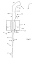
- FIG. 2 Another aspect of the invention relates to in FIG. 2 shown arrangement of a shoehorn 1 and a holding device 6, wherein the holding device 6 for at least partially encompassing a portion of the connecting portion 4 is formed.
- the holding device 6 consists in the illustrated embodiment of a plate-shaped base element 6.2 and a pair of support elements 6.1, 6.1 ', which preferably project from the base element 6.2 at right angles.
- the support elements 6.1, 6.1 ' for example, by plate-shaped elements pins, bolts o.ä. be formed and have a distance d to each other, which is formed for clamping a portion of the connecting portion 4 of the shoe bucket 1.
- the mutually spaced support elements 6.1, 6.1 ' are designed to encompass the second connecting portion 4.2 of the shoe bucket 1.
- the distance d of the support elements 6.1, 6.1 ' is slightly greater than the height h2 of the second connection section area 4.2.
- the holding device 6 For hanging and holding the shoe bucket 1, the holding device 6 itself is suspended on a wall, in particular such that the side of the support elements 6.1, 6.1 'limited area extends perpendicularly or is formed open upwards and downwards.
- the shoehorn 1 is in this case inserted into the holding device 6 in such a way that the sliding section 2 and the first connecting section area 4.1 projects downward from the holding device 6 and the second connecting section area 4.2 comes to lie between the carrier elements 6.1, 6.1 '.
- the second connecting section region 4.2 slides between the carrier elements 6.1, 6.1 'until a steady attachment between the carrier elements 6.1, 4.1, by the continuous widening of the shoe bucket 1 in the transition region between the first and second connecting section region 4.2, 4.3 6.1 'results.
- the sliding action of the shoe bucket is in this case by the consistently flat trained upper side 4.1.1, 4.2.1, 4.3.1, the likewise flat side surfaces and the flat, parallel to the top 4.2.1 of the second connecting portion 4.2 extending bottom 4.2.2 favors.
Landscapes
- Holders For Apparel And Elements Relating To Apparel (AREA)
Priority Applications (1)
| Application Number | Priority Date | Filing Date | Title |
|---|---|---|---|
| EP10007481A EP2409607A1 (fr) | 2010-07-20 | 2010-07-20 | Chausse-pied |
Applications Claiming Priority (1)
| Application Number | Priority Date | Filing Date | Title |
|---|---|---|---|
| EP10007481A EP2409607A1 (fr) | 2010-07-20 | 2010-07-20 | Chausse-pied |
Publications (1)
| Publication Number | Publication Date |
|---|---|
| EP2409607A1 true EP2409607A1 (fr) | 2012-01-25 |
Family
ID=43086314
Family Applications (1)
| Application Number | Title | Priority Date | Filing Date |
|---|---|---|---|
| EP10007481A Withdrawn EP2409607A1 (fr) | 2010-07-20 | 2010-07-20 | Chausse-pied |
Country Status (1)
| Country | Link |
|---|---|
| EP (1) | EP2409607A1 (fr) |
Cited By (2)
| Publication number | Priority date | Publication date | Assignee | Title |
|---|---|---|---|---|
| JP3370324B2 (ja) | 1991-04-25 | 2003-01-27 | 中外製薬株式会社 | ヒトインターロイキン−6受容体に対する再構成ヒト抗体 |
| DE202015005021U1 (de) | 2015-07-19 | 2015-10-06 | Axel R. Hidde | Schuhanzieher/-löffel mit Stiefelknecht |
Citations (4)
| Publication number | Priority date | Publication date | Assignee | Title |
|---|---|---|---|---|
| US3436000A (en) * | 1967-06-27 | 1969-04-01 | Jose Hernandez Batista | Shoehorn |
| GB2344272A (en) | 1998-12-04 | 2000-06-07 | Helping Hand Co Ledbury | Shoe horn gripper |
| US20020139819A1 (en) * | 2001-04-02 | 2002-10-03 | Ferraioli Michael P. | Footwear donning device |
| US6695182B1 (en) * | 2002-03-11 | 2004-02-24 | Terrance L. Shrewsbury | Extendable shoehorn device |
-
2010
- 2010-07-20 EP EP10007481A patent/EP2409607A1/fr not_active Withdrawn
Patent Citations (4)
| Publication number | Priority date | Publication date | Assignee | Title |
|---|---|---|---|---|
| US3436000A (en) * | 1967-06-27 | 1969-04-01 | Jose Hernandez Batista | Shoehorn |
| GB2344272A (en) | 1998-12-04 | 2000-06-07 | Helping Hand Co Ledbury | Shoe horn gripper |
| US20020139819A1 (en) * | 2001-04-02 | 2002-10-03 | Ferraioli Michael P. | Footwear donning device |
| US6695182B1 (en) * | 2002-03-11 | 2004-02-24 | Terrance L. Shrewsbury | Extendable shoehorn device |
Cited By (2)
| Publication number | Priority date | Publication date | Assignee | Title |
|---|---|---|---|---|
| JP3370324B2 (ja) | 1991-04-25 | 2003-01-27 | 中外製薬株式会社 | ヒトインターロイキン−6受容体に対する再構成ヒト抗体 |
| DE202015005021U1 (de) | 2015-07-19 | 2015-10-06 | Axel R. Hidde | Schuhanzieher/-löffel mit Stiefelknecht |
Similar Documents
| Publication | Publication Date | Title |
|---|---|---|
| CH665108A5 (de) | Vorrichtung zur halterung und aufbewahrung von gegenstaenden. | |
| DE102010030577A1 (de) | Blumenkasten-Halte-Vorrichtung | |
| CH622869A5 (en) | Pipe clamp, in particular for heating pipes, water-channelling pipes, gas pipes or roof-gutter pipes | |
| DE10105830A1 (de) | Weinbergstickel | |
| EP3712354A1 (fr) | Plateforme de coffrage | |
| EP3243961B1 (fr) | Glissière universelle pour nettoyage de sol | |
| EP3053426B1 (fr) | Soc d'épandage et sabot d'épandage | |
| DE60203353T2 (de) | Schubladenführung und Verfahren für die Realisierung und für die Versammlung davon | |
| DE102010052074B4 (de) | Pappmöbel | |
| DE202013102865U1 (de) | Griff | |
| EP0845626A2 (fr) | Elément de fixation pour câbles | |
| EP3243962B1 (fr) | Glissière universelle pour nettoyage de sol | |
| DE20005796U1 (de) | Leitersprosse aus Metall | |
| LU101727B1 (de) | Vorrichtung zur Verkaufswarenpräsentation | |
| DE3803755C2 (fr) | ||
| AT390708B (de) | Rechen | |
| DE102015005111A1 (de) | Spachtel zum Entfernen von Tapete und/oder Teppichböden | |
| DE29520404U1 (de) | Schuhträger | |
| DE3525280A1 (de) | In lochungen von wandungen verriegelbare befestigungsvorrichtung fuer konstruktionsteile aus kunststoff oder metall | |
| DE2518953C3 (de) | Einrichtung für das unverrückbare Ankuppeln eines Stielgriffes an ein Gefäß | |
| DE7703231U1 (de) | Konsole zur halterung von gegenstaenden an vertikal stehenden lochplatten | |
| AT413723B (de) | Distanzhalterkeil | |
| EP4446522A1 (fr) | Truelle pouvant être guidée de précision | |
| AT408201B (de) | Eispickel | |
| DE202011110712U1 (de) | Sockel zum Abdecken eines Belagrandes |
Legal Events
| Date | Code | Title | Description |
|---|---|---|---|
| AK | Designated contracting states |
Kind code of ref document: A1 Designated state(s): AL AT BE BG CH CY CZ DE DK EE ES FI FR GB GR HR HU IE IS IT LI LT LU LV MC MK MT NL NO PL PT RO SE SI SK SM TR |
|
| AX | Request for extension of the european patent |
Extension state: BA ME RS |
|
| PUAI | Public reference made under article 153(3) epc to a published international application that has entered the european phase |
Free format text: ORIGINAL CODE: 0009012 |
|
| 17P | Request for examination filed |
Effective date: 20120525 |
|
| 17Q | First examination report despatched |
Effective date: 20120703 |
|
| STAA | Information on the status of an ep patent application or granted ep patent |
Free format text: STATUS: THE APPLICATION IS DEEMED TO BE WITHDRAWN |
|
| 18D | Application deemed to be withdrawn |
Effective date: 20121114 |