EP2409657B1 - Dispositif de traitement pour endoscope - Google Patents
Dispositif de traitement pour endoscope Download PDFInfo
- Publication number
- EP2409657B1 EP2409657B1 EP09841916.1A EP09841916A EP2409657B1 EP 2409657 B1 EP2409657 B1 EP 2409657B1 EP 09841916 A EP09841916 A EP 09841916A EP 2409657 B1 EP2409657 B1 EP 2409657B1
- Authority
- EP
- European Patent Office
- Prior art keywords
- coil sheath
- treatment
- coil
- main body
- sheath
- Prior art date
- Legal status (The legal status is an assumption and is not a legal conclusion. Google has not performed a legal analysis and makes no representation as to the accuracy of the status listed.)
- Not-in-force
Links
Images




Classifications
-
- A—HUMAN NECESSITIES
- A61—MEDICAL OR VETERINARY SCIENCE; HYGIENE
- A61B—DIAGNOSIS; SURGERY; IDENTIFICATION
- A61B17/00—Surgical instruments, devices or methods
- A61B17/28—Surgical forceps
- A61B17/29—Forceps for use in minimally invasive surgery
-
- A—HUMAN NECESSITIES
- A61—MEDICAL OR VETERINARY SCIENCE; HYGIENE
- A61B—DIAGNOSIS; SURGERY; IDENTIFICATION
- A61B17/00—Surgical instruments, devices or methods
- A61B17/28—Surgical forceps
- A61B17/29—Forceps for use in minimally invasive surgery
- A61B2017/2901—Details of shaft
- A61B2017/2902—Details of shaft characterized by features of the actuating rod
-
- A—HUMAN NECESSITIES
- A61—MEDICAL OR VETERINARY SCIENCE; HYGIENE
- A61B—DIAGNOSIS; SURGERY; IDENTIFICATION
- A61B17/00—Surgical instruments, devices or methods
- A61B17/28—Surgical forceps
- A61B17/29—Forceps for use in minimally invasive surgery
- A61B2017/2901—Details of shaft
- A61B2017/2905—Details of shaft flexible
Definitions
- the present invention relates to an endoscopic treatment tool which is transendoscopically inserted into a body cavity and is employed in various procedures.
- endoscopic treatment tools provided with a treatment part such as forceps at the distal end have been known.
- a treatment part such as forceps at the distal end
- an operation part at the proximal end side of the endoscopic treatment tool is rotated.
- a treatment tool such as forceps with which opening or closing operations are conducted by pushing or pulling an operating wire or the like that is connected to the treatment part via the operation part
- compressive force is exerted in the axial direction of a coil sheath in conjunction with the opening or closing.
- a multi-strand coil sheath in which multiple wires are wound has higher rotational transmittance, but tends to compress in the axial direction. Consequently, the coil sheath compresses in the axial direction, and the axial force to be transmitted to the distal part decreases, thereby making it impossible to conduct adequate treatment, and rendering procedures more complicated.
- US Patent No. 5,271,543 discloses a surgical anastomisis stapling instrument with a flexible support shaft and anvil adjusting mechnism.
- the flexible support shaft includes a dual coil structure and connected to a tubular coupling sleeve which is distally slidable to allow the support shaft assembly to move distally to compensate for changes in length.
- the present invention is made in view of the above-described circumstances, and the object thereof is to provide an endoscopic treatment tool in which a treatment portion can be rotated by preferably following the rotational operation of the operation part even in the curved state.
- the invention provides an instrument according to claim 1. Further embodiments of the invention are described in the dependent claims.
- the endoscopic treatment tool of the present invention when the coil sheath part experiences meandering or the like within a body, and a difference in apparent length occurs between the first coil sheath and the second coil sheath, the difference in apparent length is absorbed by the movement of the second end part of the second coil sheath that is capable of relative movement with respect to the first coil sheath, and the accumulation of stress in the coil sheath part is inhibited at the time of rotational operation of the second coil sheath.
- the first coil sheath may be formed by helically winding a single wire; and the second coil sheath may be formed by helically winding multiple wires in the same direction. In this case, it is possible to optimize the compressive resistance of the first coil sheath and the rotation follow-up capability of the second coil sheath.
- a first end part and a second end part of the first coil sheath may be respectively connected to the treatment part and the operation part so as to be capable of relative rotation around an axis of the first coil sheath and incapable of relative movement in the axial direction. In this case, it is possible to enable appropriate rotational operation of the treatment part while reliably providing compressive resistance to the operation shaft member.
- the treatment part may have a pair of forcep members that can be opened and closed.
- the endoscopic treatment tool of the present invention it is possible to cause a treatment part to rotate by satisfactorily following rotational operation of an operation part, even when it is in a flexed state.
- an endoscopic treatment tool of a first embodiment of the present invention is described with reference to FIG. 1 to FIG 6 .
- an endoscopic treatment tool (hereinafter simply “treatment tool”) 1 of the present embodiment is provided with a treatment part 10 for conducting treatment of tissue within a body cavity, an operation part 20 for operating the treatment part 10, two operating wires (operation shaft members) 30 which connects the treatment part 10 and the operation part 20, and a coil sheath part 40 through which the operating wires 30 pass so as to be capable of forward and backward movement.
- FIG 2 is an enlarged sectional view of the distal portion of the treatment tool 1 including the treatment part 10.
- the treatment part 10 is configured by connecting a pair of forcep members -- a first forcep member 11 and a second forcep member 12 -- with a pivot shaft 13 so as to be capable of mutually and freely turning.
- the operating wires 30 are connected to the proximal end parts of the respective forcep members 11 and 12, more toward the proximal side than the pivot shaft 13, pass through the interior of the coil sheath part 40, and are connected to the operation part 20.
- the operation part 20 is configured by providing a long and slender main body 21, and a slider 22 that is attached so as to be capable of sliding within a fixed range in the axial direction with respect to the main body 21.
- the end parts of the operating wires 30 and the coil sheath part 40 are connected to the operation part 20; the detailed connection mode is described below.
- the coil sheath part 40 is to be transendoscopically inserted into a body cavity, and is provided with a first coil sheath 41 through which the operating wires 30 pass, and a second coil sheath 42 through which the first coil sheath 41 passes.
- the first coil sheath 41 is a so-called single-strand type coil sheath that is formed by tightly winding a single metal wire in a loop shape.
- the first coil sheath 41 imparts compressive resistance to the inserted operating wires 30, and appropriately transmits the opening and closing operation of the treatment part 10 to the treatment part 10 via the slider 22.
- the second coil sheath 42 is a so-called multi-strand type coil sheath that is formed by tightly winding multiple metal wires side-by-side in the radial direction in a loop shape.
- the second coil sheath 42 appropriately transmits the operations that serve to rotate the treatment part 10 to the treatment part 10.
- the number of metal wires that are used to form the second coil sheath 42 may be decided at one's discretion.
- first coil sheath 41 is formed with a planar metal wire
- second coil sheath 42 is formed with round rod-like metal wires
- metal wire shapes are not limited thereto, and may be appropriately selected according to design values and the like of the coil sheath part 40.
- a region of prescribed length at a distal end (first end part) 42A side of the second coil sheath 42 is worked by machining or the like so as to have a planar outer circumferential surface 42B.
- a connecting member 43 that serves to connect the treatment part 10 and the coil sheath part 40 is fixed to the distal end 42A of the second coil sheath 42 by welding or the like.
- the pivot shaft 13 is provided at more toward the distal end side than the connecting member 43, and the pivot shaft 13 is incapable of relative movement with respect to the connecting member 43.
- the proximal end part of the connecting member 43 is formed in a tubular shape, and its inner surface is provided with a first inner surface 43A that is connected and fixed to the outer circumferential surface of the second coil sheath 42, and a second inner surface 43B that is formed with a smaller diameter than the first inner surface 43A more toward the distal end side than the first inner surface 43A.
- a distal end 41 A of the first coil sheath 41 that passes through the second coil sheath 42 is inserted into the second inner surface 43B, and is fixed to the connecting member 43.
- the distal end 42A of the second coil sheath 42 that is fixed to the first inner surface 43A of the connecting member 43 is incapable of rotating around its own axis with respect to the connecting member 43, and is incapable of relative movement in the axial direction with respect to the first coil sheath 41.
- connection mode of the connecting member 43 and the coil sheath part is not specifically limited to that described above.
- shape of the site in the connecting member where the coil sheath part is fixed does not have to be tubular.
- the outer circumferential surface of the second coil sheath 42 is covered by an insulating tube 44.
- the tube 44 is formed with an insulating material, and an engagement member 45 of approximately cylindrical shape is attached to its distal end part by press fitting or the like.
- the engagement member 45 engages with the distal end part of the outer circumferential surface 42B whose outer diameter is diminished by the aforementioned work.
- the tube 44 is attached so that it is capable of relative rotation around an axis with respect to the second coil sheath 42.
- the tube 44 is not indispensable to the treatment tool of the present invention, and may be provided as necessary in cases where insulating treatment of the coil sheath part 40 is required. Accordingly, it is also acceptable to configure the treatment tool 1 so that the outer circumferential surface of the second coil sheath 42 is uncovered and exposed.
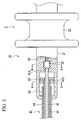
- FIG 3 is an enlarged sectional view of the connection site of the operation part 20 and the coil sheath part 40.
- the proximal end part of the coil sheath part 40 is connected to the main body 21.
- the proximal end part of the tube 44 is inserted into the distal end part of the main body 21 so as to be capable of relative rotation, and the proximal end (second end part) 42C of the second coil sheath 42 is fixed to the sliding member 23 inside the main body 21.
- FIG 4 is a sectional view along the A-A line of FIG 3 .
- the sectional shape of the sliding member 23 is approximately rectangular in the widthwise direction of the main body 21, when the main body 21 is axially rotated, the sliding member 23 and the second coil sheath 42 also axially rotate in conjunction with the main body 21.
- the sliding member 23 is capable of sliding inside a slide groove 24 that is provided inside the main body 21 so as to extend lengthwise. That is, the proximal end 42C of the second coil sheath 42 is attached so as to be incapable of axially turning with respect to the main body 21, and capable of relative movement in the axial direction with respect to the main body 21 and the first coil sheath 41. It is preferable to set the positional relation of the sliding member 23 in the slide groove 24 so that the sliding member 23 never makes contact with the lengthwise end faces of the slide groove 24 in order that strain does not occur in the coil sheath part 40 even when the coil sheath part 40 is maximally flexed.
- the proximal end 41B of the first coil sheath 41 which extends from the second coil sheath 42 is fixed to an engagement member 25.
- the engagement member 25 is approximately cylindrical in shape, and has a larger outer diameter than the first coil sheath 41. Accordingly, the proximal end 41B of the first coil sheath 41 is attached so as to be capable of axial rotation and incapable of relative movement in the axial direction with respect to the main body 21.
- the operating wires 30 which extend from the first coil sheath 41 pass through the interior of the main body 21, and are connected to the slider 22.
- target tissue tissue as a treatment target within a body cavity
- the user moves the slider 22 backward relative to the main body 21 to put the treatment part 10 into a closed condition, and inserts the treatment part 10 and the coil sheath part 40 of the treatment tool 1 into the forceps channel (not illustrated in the drawings) of the endoscope. The user then projects the treatment part 10 from forceps channel.
- the slider 22 When treatment is conducted, the slider 22 is slid toward the distal end of the main body 21, whereupon the operating wires 30 which are connected to the slider 22 move forward relative to the coil sheath part 40.
- the pivot shaft 13 is incapable of relative movement with respect to the connecting member 43 that is attached to the distal end of the coil sheath part 40, with the result that the first forcep member 11 and second forcep member 12 are respectively turned centering on the pivot shaft 13, and the treatment part 10 is opened.
- the user grasps the main body 21 of the operation part 20, and rotates it around the axis, whereupon the sliding member 23 is axially rotated in conjunction with the main body 21, as are the second coil sheath 42 that is connected to the sliding member 23 and the treatment part 10 that is attached to the distal end of the second coil sheath 42. In this manner, it is possible to adjust the opening/closing orientation of the treatment part 10.
- the treatment part 10 and the main body 21 of the operation part 20 are connected by the multi-strand type second coil sheath 42, the torque generated by the above-described rotational operation of the main body 21 by the user is satisfactorily transmitted to the treatment part 10 by the second coil sheath 42.
- the treatment part 10 axially rotates while satisfactorily following the rotational operation of the main body 21, thereby enabling adjustment of the opening/closing orientation of the treatment part 10 to be easily conducted.
- meandering, flexing or the like may occur in the long inserted portion of the endoscope and in the coil sheath part 40 of the treatment tool 1 that passes through the inserted portion.
- the sliding member 23 to which the proximal end 42C of the second coil sheath 42 is connected slides in the direction shown by the arrow within the slide groove 24 inside the main body 21, with the result that the proximal end 42C of the second coil sheath 42 undergoes relative movement in the axial direction with respect to the first coil sheath 41, absorbing the apparent length. In this manner, the accumulation of strain in the coil sheath part 40 accompanying rotational operation is inhibited.
- FIG 6 is shown with omission of the tube 44 in order to facilitate viewing of the drawing.
- the two ends of the multi-strand type second coil sheath 42 are respectively attached to the treatment part 10 and the main body 21 of the operation part 20 so as to be incapable of turning. Accordingly, the torque generated by the axial rotation of the main body 21 is efficiently transmitted to the treatment part 10, causing axial rotation of the treatment part 10, and enabling adjustment of orientation relative to the target tissue to be satisfactorily conducted.
- proximal end 42C of the second coil sheath 42 is capable of relative movement in the axial direction with respect to the first coil sheath 41 by the sliding member 23 and the slide groove 24 provided in the main body 21, even in the case where the coil sheath part 40 meanders within the body cavity, accumulation of strain in the coil sheath part 40 is inhibited. Consequently, it is possible to satisfactorily prevent rotational skipping when the treatment part 10 is axially rotated.
- the coil sheath part 40 it is also acceptable to configure the coil sheath part 40 so that the second coil sheath 42 is inserted through the first coil sheath 41.
- the proximal end 41B of the first coil sheath 41 is attached to the main body 21 by the engagement member 25 more toward the distal end side than the slide groove 24, and the sliding member 23 is attached to the proximal end 42C of the second coil sheath 42 that extends from the proximal end 41 B of the first coil sheath 41 and is disposed in the slide groove 24. Even in this case, it is possible to obtain the same effect as the treatment tool 1 described above.
- the distal end 41 A of the first coil sheath 41 so that it is capable of relative axial rotation with respect to the distal end member.
- the first coil sheath 41 is also capable of relative axial rotation with respect to the second coil sheath 42. Accordingly, it is possible to configure a treatment tool that has good operational feel in which rotation of the second coil sheath 42 becomes smoother when the treatment part 10 is rotationally operated.
- a treatment tool 51 of the present example is the mode of connection of the coil sheath part to the treatment part and the operation part.
- FIG 8 is an enlarged sectional view of the vicinity of the distal end of the coil sheath part 40 of the treatment tool 51.
- the treatment part 10 and the coil sheath 40 are connected by a connecting member 52.
- the connecting member 52 has longer axial dimensions than the connecting member 43 of the first embodiment, and is attached so as to be capable of relative rotation around its own axis with respect to the tube 44.
- a slide groove 53 having the same configuration as the slide groove 24 of the first embodiment is provided inside the connecting member 52, and a sliding member 54 is attached to the distal end 42A of the second coil sheath 42 and is disposed within the slide groove 53.
- An engagement member 55 having the same configuration as the engagement member 25 of the first embodiment is attached to the distal end 41 A of the first coil sheath 41 that extends from the distal end 42A of the second coil sheath 42, and the first coil sheath 41 is attached to the connecting member 52 in approximately the same mode as the connection of the first coil sheath 41 and the main body 21 in the first embodiment.
- the distal end 41A of the first coil sheath 41 is attached so that it is capable of relative rotation around its own axis and incapable of relative movement in the axial direction with respect to the connecting member 52 in the treatment part 10 side.
- the distal end 42A of the second coil sheath 42 is attached so that it is incapable of relative rotation around its own axis and capable of relative movement in the axial direction with respect to the connecting member 52.
- the distal end 42A of the second coil sheath 42 is configured so that it is capable of axial rotation and capable of relative movement in the axial direction with respect to the first coil sheath 41.
- the proximal end 42C of the second coil sheath 42 is not illustrated in the drawings, but is connected so that it is incapable of axial rotation and incapable of relative movement in the axial direction with respect to the operation part 20, in a manner that is approximately identical to the mode of connection of the distal end 42A to the connecting member 43 in the treatment tool 1.
- the distal end 42A of the second coil sheath 42 undergoes relative movement in the axial direction with respect to the first coil sheath 41 by moving toward the proximal end within the slide groove 53.
- the difference in the apparent length of the first coil sheath 41 and the second coil sheath 42 is absorbed, and accumulation of strain in the coil sheath part 40 is inhibited. Accordingly, as with the treatment tool 1 of the first embodiment, it is possible to satisfactorily conduct rotational operation of the treatment part 10 while suppressing rotational skipping.
- the first coil sheath is a single-strand type coil sheath
- the second coil sheath is a multi-strand type coil sheath
- the combination of coil sheaths is not limited thereto.
- the second coil sheath is a five-strand type coil sheath composed of five wires.
- both the first coil sheath and the second coil sheath are multi-strand type coil sheaths, and in this case as well, it is possible to obtain the same effects, because the first coil sheath has a higher compressive resistance than the second coil sheath, and the second coil sheath has a higher rotation follow-on capability than the first coil sheath.
- first coil sheath composed of three wires or less.
- the present disclosure describes the case where only one of either the proximal end part and the distal end part of the second coil sheath was capable of relative movement in the axial direction with respect to the first coil sheath, but as it is possible to obtain a similar effect so long as at least one of the end parts of the second coil sheath is capable of relative movement in the axial direction with respect to the first coil sheath, it is also acceptable to adopt a configuration where both the proximal end part and distal end part are capable of relative movement in the axial direction with respect to the first coil sheath.
- the treatment part is composed of a pair of forcep members, but the treatment part in the treatment tool of the present invention is not limited thereto. That is, so long as it is a treatment part that requires adjustment of orientation relative to tissue as treatment target, it is possible to apply treatment parts of any type such as, for example, a snare wire or a so-called two-legged forceps.
- the endoscopic treatment tool of the present invention it is possible to cause a treatment part to rotate by satisfactorily following rotational operation of an operation part, even when it is in a flexed state.
Landscapes
- Health & Medical Sciences (AREA)
- Surgery (AREA)
- Life Sciences & Earth Sciences (AREA)
- Biomedical Technology (AREA)
- Nuclear Medicine, Radiotherapy & Molecular Imaging (AREA)
- Engineering & Computer Science (AREA)
- Ophthalmology & Optometry (AREA)
- Heart & Thoracic Surgery (AREA)
- Medical Informatics (AREA)
- Molecular Biology (AREA)
- Animal Behavior & Ethology (AREA)
- General Health & Medical Sciences (AREA)
- Public Health (AREA)
- Veterinary Medicine (AREA)
- Surgical Instruments (AREA)
Claims (5)
- Outil de traitement endoscopique (1, 51), comprenant :une partie de traitement (10) qui est adaptée pour réaliser un traitement de tissu à l'intérieur d'une cavité de corps ;une partie d'actionnement (20) qui est adaptée pour actionner la partie de traitement (10) ;un élément d'arbre d'actionnement (30) qui connecte la partie de traitement (10) et la partie d'actionnement (20) ; etune partie de gaine en spirale (40) à travers laquelle passe l'élément d'arbre d'actionnement de sorte que l'élément d'arbre d'actionnement est capable de se déplacer vers l'avant ou vers l'arrière,dans lequel la partie de gaine en spirale (40) comprendune première gaine en spirale (41) formée en enroulant de manière hélicoïdale un, deux ou trois fils ; etune deuxième gaine en spirale (42) qui présente une résistance à la compression plus faible que la première gaine en spirale (41), et qui présente une capacité de suivi de rotation plus élevée que la première bobine en spirale (41), dans lequella première gaine en spirale (41) et la deuxième gaine en spirale (42) sont disposées de façon à se chevaucher coaxialement et radialement ;une première partie d'extrémité (42A) et une deuxième partie d'extrémité (42C) de la deuxième gaine en spirale (42) sont respectivement connectées à la partie de traitement (10) et à la partie d'actionnement (20) de façon à être incapables d'une rotation relative autour d'un axe de la deuxième gaine en spirale (42) ;une première partie d'extrémité (41A) de la première gaine en spirale (41) est incapable de se déplacer dans la direction axiale par rapport à la partie de traitement (10), dans lequella partie d'actionnement (20) comprend un corps principal (21) dans lequel un espace de coulissement allongé dans une direction longitudinale à l'intérieur du corps principal (21) est formé et un élément coulissant (22) couplé en coulissement au corps principal (21) et configuré pour être capable de coulisser de manière relative par rapport au corps principal (21),l'élément d'arbre d'actionnement (30) connecte la partie de traitement (10) et l'élément coulissant (22), l'élément d'arbre d'actionnement (30) est capable de se déplacer par rapport au corps principal (21) dans une direction axiale de l'élément d'arbre d'actionnement (30),la première partie d'extrémité (41A) et une deuxième partie d'extrémité (41B) de la première gaine en spirale (41) sont respectivement connectées à la partie de traitement (10) et au corps principal (21) de façon à être incapables de se déplacer par rapport à la partie de traitement (10) et au corps principal (21) dans la direction axiale de la première gaine en spirale (41),la partie d'actionnement (20), la deuxième gaine en spirale (42) et la partie de traitement (10) tournent par rapport à la première gaine en spirale (41),
caractérisé en ce quela deuxième partie d'extrémité (42C) de la deuxième gaine en spirale (42) est capable de se déplacer librement dans une direction axiale par rapport à la première gaine en spirale (41) ; la deuxième partie d'extrémité (42C) de la deuxième gaine en spirale (42) est connectée à un élément coulissant (23) qui est configuré pour coulisser librement à l'intérieur de l'espace de coulissement dans une direction axiale de la deuxième gaine en spirale (42) ;la deuxième partie d'extrémité (42C) de la deuxième gaine en spirale (42) et l'élément coulissant (23) sont insérés dans l'espace de coulissement et coulissent librement à l'intérieur de l'espace de coulissement dans une direction axiale de la première gaine en spirale (41), la deuxième partie d'extrémité (42C) de la deuxième gaine en spirale (42) et l'élément coulissant (23) sont configurés pour être incapables de tourner autour de l'axe de la deuxième gaine en spirale (42) par rapport au corps principal (21) ; etl'élément coulissant (23) coulisse à l'intérieur de l'espace de coulissement dans la direction axiale de la deuxième gaine en spirale (42) conformément à une différence de longueur entre la première gaine en spirale (41) et la deuxième gaine en spirale (42) qui survient lors de la courbure de la partie de gaine en spirale (40). - Outil de traitement endoscopique (1, 51) selon la revendication 1,
dans lequel la première partie d'extrémité (42A) de la deuxième gaine en spirale (42) est incapable de se déplacer dans la direction axiale par rapport à la première gaine en spirale (41). - Outil de traitement endoscopique (1, 51) selon la revendication 1, dans lequel :la première gaine en spirale (41) est formée en enroulant de manière hélicoïdale un fil unique ; etla deuxième gaine en spirale (42) est formée en enroulant de manière hélicoïdale de multiples fils dans la même direction.
- Outil de traitement endoscopique (1, 51) selon la revendication 1, dans lequel la première partie d'extrémité (41A) de la première gaine en spirale (41) et une deuxième partie d'extrémité (41B) de la première gaine en spirale (41) sont respectivement connectées à la partie de traitement (10) et à la partie d'actionnement (20) de façon à être capables d'une rotation relative autour d'un axe de la première gaine en spirale (41) et incapables d'un mouvement relatif dans la direction axiale.
- Outil de traitement endoscopique selon la revendication 1, dans lequel la partie de traitement (10) comporte une paire d'éléments de pince (11, 12) qui est capable d'être ouverte et fermée.
Applications Claiming Priority (2)
| Application Number | Priority Date | Filing Date | Title |
|---|---|---|---|
| JP2009066248 | 2009-03-18 | ||
| PCT/JP2009/070915 WO2010106714A1 (fr) | 2009-03-18 | 2009-12-15 | Dispositif de traitement pour endoscope |
Publications (3)
| Publication Number | Publication Date |
|---|---|
| EP2409657A1 EP2409657A1 (fr) | 2012-01-25 |
| EP2409657A4 EP2409657A4 (fr) | 2013-10-23 |
| EP2409657B1 true EP2409657B1 (fr) | 2016-04-20 |
Family
ID=42739380
Family Applications (1)
| Application Number | Title | Priority Date | Filing Date |
|---|---|---|---|
| EP09841916.1A Not-in-force EP2409657B1 (fr) | 2009-03-18 | 2009-12-15 | Dispositif de traitement pour endoscope |
Country Status (5)
| Country | Link |
|---|---|
| US (1) | US8974492B2 (fr) |
| EP (1) | EP2409657B1 (fr) |
| JP (1) | JP4659145B2 (fr) |
| CN (1) | CN102281826B (fr) |
| WO (1) | WO2010106714A1 (fr) |
Families Citing this family (16)
| Publication number | Priority date | Publication date | Assignee | Title |
|---|---|---|---|---|
| CN103002821B (zh) * | 2010-11-01 | 2015-04-01 | 奥林巴斯医疗株式会社 | 处理器具 |
| EP2529680B1 (fr) * | 2010-12-28 | 2016-06-01 | Olympus Corporation | Dispositif de traitement pour endoscop |
| DE102011103283A1 (de) * | 2011-05-26 | 2012-11-29 | Olympus Winter & Ibe Gmbh | Chirurgisches Schaftinstrument |
| EP2810607B1 (fr) * | 2012-03-21 | 2016-05-18 | Olympus Corporation | Instrument de traitement endoscopique |
| JP6110098B2 (ja) * | 2012-10-12 | 2017-04-05 | 株式会社ハイレックスコーポレーション | 鉗子装置 |
| JP6043037B1 (ja) * | 2015-02-13 | 2016-12-14 | オリンパス株式会社 | マニピュレータ |
| CN107249831B (zh) * | 2015-07-17 | 2020-06-30 | 奥林巴斯株式会社 | 机械手 |
| CN108697485B (zh) * | 2016-02-10 | 2021-06-08 | 奥林巴斯株式会社 | 操纵器系统 |
| CN109788966B (zh) * | 2016-10-12 | 2021-07-27 | 奥林巴斯株式会社 | 处置器具用旋转机构 |
| JP6775238B2 (ja) * | 2016-10-26 | 2020-10-28 | レイクR&D株式会社 | 内視鏡用処置具 |
| CN109381237B (zh) * | 2017-08-02 | 2024-02-13 | 上海市嘉定区安亭医院 | 一种用于消化内镜下微创手术的血管钳 |
| CN109381243B (zh) * | 2017-08-02 | 2024-02-13 | 上海市嘉定区安亭医院 | 一种用于消化内镜手术具有电凝功能的血管钳 |
| CN109381254B (zh) * | 2017-08-02 | 2024-02-13 | 上海市嘉定区安亭医院 | 一种用于消化内镜手术具有电凝功能的持针钳 |
| CN109381232B (zh) * | 2017-08-02 | 2024-02-13 | 上海市嘉定区安亭医院 | 一种用于消化内镜下微创手术的持针钳 |
| WO2021005670A1 (fr) * | 2019-07-08 | 2021-01-14 | オリンパス株式会社 | Outil de traitement destiné à un endoscope |
| EP4417153A1 (fr) * | 2023-02-15 | 2024-08-21 | Finemedix Co., Ltd. | Pince hémostatique pour endoscope |
Family Cites Families (18)
| Publication number | Priority date | Publication date | Assignee | Title |
|---|---|---|---|---|
| US4742817A (en) * | 1985-05-15 | 1988-05-10 | Olympus Optical Co., Ltd. | Endoscopic apparatus having a bendable insertion section |
| JPH0347246A (ja) * | 1989-04-13 | 1991-02-28 | Olympus Optical Co Ltd | 内視鏡用処置具 |
| US5271543A (en) * | 1992-02-07 | 1993-12-21 | Ethicon, Inc. | Surgical anastomosis stapling instrument with flexible support shaft and anvil adjusting mechanism |
| US5501694A (en) * | 1992-11-13 | 1996-03-26 | Scimed Life Systems, Inc. | Expandable intravascular occlusion material removal devices and methods of use |
| JP3498426B2 (ja) * | 1995-05-16 | 2004-02-16 | 富士写真光機株式会社 | 内視鏡の可撓管 |
| US6461310B1 (en) * | 1997-10-29 | 2002-10-08 | Symbiosis Corp | Endoscopic bioptome with a hard stop to control biting force |
| JP3634655B2 (ja) * | 1999-02-09 | 2005-03-30 | ペンタックス株式会社 | 内視鏡用生検鉗子 |
| US6409727B1 (en) * | 1999-10-15 | 2002-06-25 | Scimed Life Systems, Inc. | Multifilar flexible rotary shaft and medical instruments incorporating the same |
| JP4166414B2 (ja) * | 2000-05-17 | 2008-10-15 | オリンパス株式会社 | 内視鏡用処置具 |
| US7341564B2 (en) * | 2001-05-03 | 2008-03-11 | Boston Scientific Scimed, Inc. | Biopsy forceps device with transparent outer sheath |
| JP4056989B2 (ja) * | 2003-06-24 | 2008-03-05 | オリンパス株式会社 | 内視鏡処置具 |
| US7506790B2 (en) * | 2004-07-28 | 2009-03-24 | Ethicon Endo-Surgery, Inc. | Surgical instrument incorporating an electrically actuated articulation mechanism |
| JP2008148738A (ja) * | 2006-12-14 | 2008-07-03 | Olympus Medical Systems Corp | 内視鏡用処置具 |
| EP1955657B1 (fr) * | 2007-02-08 | 2011-01-12 | Olympus Medical Systems Corp. | Outil de traitement pour endoscope |
| JP5042700B2 (ja) | 2007-02-08 | 2012-10-03 | オリンパスメディカルシステムズ株式会社 | 内視鏡用処置具 |
| JP2008237266A (ja) * | 2007-03-26 | 2008-10-09 | Fujinon Corp | 内視鏡用処置具 |
| US8663221B2 (en) * | 2007-06-08 | 2014-03-04 | Olympus Medical Systems Corp. | Endoscopic treatment tool |
| JP2009066248A (ja) | 2007-09-14 | 2009-04-02 | Daikoku Denki Co Ltd | パチンコ遊技機 |
-
2009
- 2009-12-15 CN CN2009801545830A patent/CN102281826B/zh active Active
- 2009-12-15 EP EP09841916.1A patent/EP2409657B1/fr not_active Not-in-force
- 2009-12-15 WO PCT/JP2009/070915 patent/WO2010106714A1/fr not_active Ceased
- 2009-12-15 JP JP2010537176A patent/JP4659145B2/ja active Active
-
2010
- 2010-09-17 US US12/884,680 patent/US8974492B2/en active Active
Non-Patent Citations (1)
| Title |
|---|
| None * |
Also Published As
| Publication number | Publication date |
|---|---|
| CN102281826A (zh) | 2011-12-14 |
| US8974492B2 (en) | 2015-03-10 |
| CN102281826B (zh) | 2013-11-06 |
| JPWO2010106714A1 (ja) | 2012-09-20 |
| EP2409657A4 (fr) | 2013-10-23 |
| EP2409657A1 (fr) | 2012-01-25 |
| US20110071564A1 (en) | 2011-03-24 |
| JP4659145B2 (ja) | 2011-03-30 |
| WO2010106714A1 (fr) | 2010-09-23 |
Similar Documents
| Publication | Publication Date | Title |
|---|---|---|
| US8974492B2 (en) | Endoscopic treatment tool | |
| CN101238971B (zh) | 内窥镜用处理器具 | |
| EP1852073B1 (fr) | Poignée d'instrument médical et instrument médical doté d'une poignée | |
| CN114760904B (zh) | 具有多个自由度的医疗装置及相关方法 | |
| EP1325709B1 (fr) | Instrument microchirurgical flexible pourvu d'un crochet de sureté rotatif | |
| EP1955658B1 (fr) | Outil de traitement endoscopique | |
| JP3417778B2 (ja) | 内視鏡用処置具 | |
| EP1491153B1 (fr) | Outil de traitement pour un endoscope | |
| EP2540240B1 (fr) | Outil thérapeutique pour endoscopes | |
| EP2465446A1 (fr) | Instrument de traitement pour endoscope | |
| EP2111806B1 (fr) | Instrument de traitement d'endoscope | |
| US20100298638A1 (en) | Endoscopic Instrument with Bi-Laterally Widened Cam-Slot at End Effector | |
| US20100298852A1 (en) | Endoscopic Scissors Instrument with Friction Enhancing Tissue Stops | |
| EP2415408B1 (fr) | Dispositif de traitement | |
| JP2009101153A (ja) | 内視鏡用処置具および内視鏡用処置具の製造方法 | |
| JP5171471B2 (ja) | 内視鏡用処置具 | |
| EP1736093B1 (fr) | Système de traitement endoscopique | |
| EP2529680B1 (fr) | Dispositif de traitement pour endoscop | |
| US20110245813A1 (en) | Treatment tool | |
| JP2021006142A (ja) | 内視鏡用処置具 |
Legal Events
| Date | Code | Title | Description |
|---|---|---|---|
| PUAI | Public reference made under article 153(3) epc to a published international application that has entered the european phase |
Free format text: ORIGINAL CODE: 0009012 |
|
| 17P | Request for examination filed |
Effective date: 20110801 |
|
| AK | Designated contracting states |
Kind code of ref document: A1 Designated state(s): AT BE BG CH CY CZ DE DK EE ES FI FR GB GR HR HU IE IS IT LI LT LU LV MC MK MT NL NO PL PT RO SE SI SK SM TR |
|
| DAX | Request for extension of the european patent (deleted) | ||
| REG | Reference to a national code |
Ref country code: DE Ref legal event code: R079 Ref document number: 602009038120 Country of ref document: DE Free format text: PREVIOUS MAIN CLASS: A61B0017280000 Ipc: A61B0017290000 |
|
| A4 | Supplementary search report drawn up and despatched |
Effective date: 20130925 |
|
| RIC1 | Information provided on ipc code assigned before grant |
Ipc: A61B 17/29 20060101AFI20130919BHEP Ipc: A61B 1/00 20060101ALI20130919BHEP Ipc: A61B 17/28 20060101ALI20130919BHEP |
|
| 17Q | First examination report despatched |
Effective date: 20140731 |
|
| RAP1 | Party data changed (applicant data changed or rights of an application transferred) |
Owner name: OLYMPUS CORPORATION |
|
| GRAP | Despatch of communication of intention to grant a patent |
Free format text: ORIGINAL CODE: EPIDOSNIGR1 |
|
| INTG | Intention to grant announced |
Effective date: 20151113 |
|
| GRAR | Information related to intention to grant a patent recorded |
Free format text: ORIGINAL CODE: EPIDOSNIGR71 |
|
| GRAS | Grant fee paid |
Free format text: ORIGINAL CODE: EPIDOSNIGR3 |
|
| GRAA | (expected) grant |
Free format text: ORIGINAL CODE: 0009210 |
|
| INTG | Intention to grant announced |
Effective date: 20160308 |
|
| AK | Designated contracting states |
Kind code of ref document: B1 Designated state(s): AT BE BG CH CY CZ DE DK EE ES FI FR GB GR HR HU IE IS IT LI LT LU LV MC MK MT NL NO PL PT RO SE SI SK SM TR |
|
| REG | Reference to a national code |
Ref country code: GB Ref legal event code: FG4D |
|
| REG | Reference to a national code |
Ref country code: CH Ref legal event code: EP |
|
| REG | Reference to a national code |
Ref country code: AT Ref legal event code: REF Ref document number: 791496 Country of ref document: AT Kind code of ref document: T Effective date: 20160515 |
|
| REG | Reference to a national code |
Ref country code: IE Ref legal event code: FG4D |
|
| REG | Reference to a national code |
Ref country code: DE Ref legal event code: R096 Ref document number: 602009038120 Country of ref document: DE |
|
| REG | Reference to a national code |
Ref country code: LT Ref legal event code: MG4D |
|
| REG | Reference to a national code |
Ref country code: AT Ref legal event code: MK05 Ref document number: 791496 Country of ref document: AT Kind code of ref document: T Effective date: 20160420 |
|
| RAP2 | Party data changed (patent owner data changed or rights of a patent transferred) |
Owner name: OLYMPUS CORPORATION |
|
| REG | Reference to a national code |
Ref country code: NL Ref legal event code: MP Effective date: 20160420 |
|
| RAP2 | Party data changed (patent owner data changed or rights of a patent transferred) |
Owner name: OLYMPUS CORPORATION |
|
| PG25 | Lapsed in a contracting state [announced via postgrant information from national office to epo] |
Ref country code: NL Free format text: LAPSE BECAUSE OF FAILURE TO SUBMIT A TRANSLATION OF THE DESCRIPTION OR TO PAY THE FEE WITHIN THE PRESCRIBED TIME-LIMIT Effective date: 20160420 Ref country code: NO Free format text: LAPSE BECAUSE OF FAILURE TO SUBMIT A TRANSLATION OF THE DESCRIPTION OR TO PAY THE FEE WITHIN THE PRESCRIBED TIME-LIMIT Effective date: 20160720 Ref country code: PL Free format text: LAPSE BECAUSE OF FAILURE TO SUBMIT A TRANSLATION OF THE DESCRIPTION OR TO PAY THE FEE WITHIN THE PRESCRIBED TIME-LIMIT Effective date: 20160420 Ref country code: FI Free format text: LAPSE BECAUSE OF FAILURE TO SUBMIT A TRANSLATION OF THE DESCRIPTION OR TO PAY THE FEE WITHIN THE PRESCRIBED TIME-LIMIT Effective date: 20160420 Ref country code: LT Free format text: LAPSE BECAUSE OF FAILURE TO SUBMIT A TRANSLATION OF THE DESCRIPTION OR TO PAY THE FEE WITHIN THE PRESCRIBED TIME-LIMIT Effective date: 20160420 |
|
| PG25 | Lapsed in a contracting state [announced via postgrant information from national office to epo] |
Ref country code: LV Free format text: LAPSE BECAUSE OF FAILURE TO SUBMIT A TRANSLATION OF THE DESCRIPTION OR TO PAY THE FEE WITHIN THE PRESCRIBED TIME-LIMIT Effective date: 20160420 Ref country code: HR Free format text: LAPSE BECAUSE OF FAILURE TO SUBMIT A TRANSLATION OF THE DESCRIPTION OR TO PAY THE FEE WITHIN THE PRESCRIBED TIME-LIMIT Effective date: 20160420 Ref country code: GR Free format text: LAPSE BECAUSE OF FAILURE TO SUBMIT A TRANSLATION OF THE DESCRIPTION OR TO PAY THE FEE WITHIN THE PRESCRIBED TIME-LIMIT Effective date: 20160721 Ref country code: AT Free format text: LAPSE BECAUSE OF FAILURE TO SUBMIT A TRANSLATION OF THE DESCRIPTION OR TO PAY THE FEE WITHIN THE PRESCRIBED TIME-LIMIT Effective date: 20160420 Ref country code: SE Free format text: LAPSE BECAUSE OF FAILURE TO SUBMIT A TRANSLATION OF THE DESCRIPTION OR TO PAY THE FEE WITHIN THE PRESCRIBED TIME-LIMIT Effective date: 20160420 Ref country code: ES Free format text: LAPSE BECAUSE OF FAILURE TO SUBMIT A TRANSLATION OF THE DESCRIPTION OR TO PAY THE FEE WITHIN THE PRESCRIBED TIME-LIMIT Effective date: 20160420 Ref country code: PT Free format text: LAPSE BECAUSE OF FAILURE TO SUBMIT A TRANSLATION OF THE DESCRIPTION OR TO PAY THE FEE WITHIN THE PRESCRIBED TIME-LIMIT Effective date: 20160822 |
|
| PG25 | Lapsed in a contracting state [announced via postgrant information from national office to epo] |
Ref country code: BE Free format text: LAPSE BECAUSE OF FAILURE TO SUBMIT A TRANSLATION OF THE DESCRIPTION OR TO PAY THE FEE WITHIN THE PRESCRIBED TIME-LIMIT Effective date: 20160420 Ref country code: IT Free format text: LAPSE BECAUSE OF FAILURE TO SUBMIT A TRANSLATION OF THE DESCRIPTION OR TO PAY THE FEE WITHIN THE PRESCRIBED TIME-LIMIT Effective date: 20160420 |
|
| REG | Reference to a national code |
Ref country code: DE Ref legal event code: R097 Ref document number: 602009038120 Country of ref document: DE |
|
| PG25 | Lapsed in a contracting state [announced via postgrant information from national office to epo] |
Ref country code: RO Free format text: LAPSE BECAUSE OF FAILURE TO SUBMIT A TRANSLATION OF THE DESCRIPTION OR TO PAY THE FEE WITHIN THE PRESCRIBED TIME-LIMIT Effective date: 20160420 Ref country code: SK Free format text: LAPSE BECAUSE OF FAILURE TO SUBMIT A TRANSLATION OF THE DESCRIPTION OR TO PAY THE FEE WITHIN THE PRESCRIBED TIME-LIMIT Effective date: 20160420 Ref country code: DK Free format text: LAPSE BECAUSE OF FAILURE TO SUBMIT A TRANSLATION OF THE DESCRIPTION OR TO PAY THE FEE WITHIN THE PRESCRIBED TIME-LIMIT Effective date: 20160420 Ref country code: CZ Free format text: LAPSE BECAUSE OF FAILURE TO SUBMIT A TRANSLATION OF THE DESCRIPTION OR TO PAY THE FEE WITHIN THE PRESCRIBED TIME-LIMIT Effective date: 20160420 Ref country code: EE Free format text: LAPSE BECAUSE OF FAILURE TO SUBMIT A TRANSLATION OF THE DESCRIPTION OR TO PAY THE FEE WITHIN THE PRESCRIBED TIME-LIMIT Effective date: 20160420 |
|
| PLBE | No opposition filed within time limit |
Free format text: ORIGINAL CODE: 0009261 |
|
| STAA | Information on the status of an ep patent application or granted ep patent |
Free format text: STATUS: NO OPPOSITION FILED WITHIN TIME LIMIT |
|
| PG25 | Lapsed in a contracting state [announced via postgrant information from national office to epo] |
Ref country code: SM Free format text: LAPSE BECAUSE OF FAILURE TO SUBMIT A TRANSLATION OF THE DESCRIPTION OR TO PAY THE FEE WITHIN THE PRESCRIBED TIME-LIMIT Effective date: 20160420 |
|
| 26N | No opposition filed |
Effective date: 20170123 |
|
| PG25 | Lapsed in a contracting state [announced via postgrant information from national office to epo] |
Ref country code: SI Free format text: LAPSE BECAUSE OF FAILURE TO SUBMIT A TRANSLATION OF THE DESCRIPTION OR TO PAY THE FEE WITHIN THE PRESCRIBED TIME-LIMIT Effective date: 20160420 |
|
| REG | Reference to a national code |
Ref country code: CH Ref legal event code: PL |
|
| GBPC | Gb: european patent ceased through non-payment of renewal fee |
Effective date: 20161215 |
|
| PG25 | Lapsed in a contracting state [announced via postgrant information from national office to epo] |
Ref country code: MC Free format text: LAPSE BECAUSE OF FAILURE TO SUBMIT A TRANSLATION OF THE DESCRIPTION OR TO PAY THE FEE WITHIN THE PRESCRIBED TIME-LIMIT Effective date: 20160420 |
|
| REG | Reference to a national code |
Ref country code: FR Ref legal event code: ST Effective date: 20170831 |
|
| REG | Reference to a national code |
Ref country code: IE Ref legal event code: MM4A |
|
| PG25 | Lapsed in a contracting state [announced via postgrant information from national office to epo] |
Ref country code: CH Free format text: LAPSE BECAUSE OF NON-PAYMENT OF DUE FEES Effective date: 20161231 Ref country code: LI Free format text: LAPSE BECAUSE OF NON-PAYMENT OF DUE FEES Effective date: 20161231 Ref country code: FR Free format text: LAPSE BECAUSE OF NON-PAYMENT OF DUE FEES Effective date: 20170102 Ref country code: LU Free format text: LAPSE BECAUSE OF NON-PAYMENT OF DUE FEES Effective date: 20161215 |
|
| PG25 | Lapsed in a contracting state [announced via postgrant information from national office to epo] |
Ref country code: IE Free format text: LAPSE BECAUSE OF NON-PAYMENT OF DUE FEES Effective date: 20161215 Ref country code: GB Free format text: LAPSE BECAUSE OF NON-PAYMENT OF DUE FEES Effective date: 20161215 |
|
| PG25 | Lapsed in a contracting state [announced via postgrant information from national office to epo] |
Ref country code: HU Free format text: LAPSE BECAUSE OF FAILURE TO SUBMIT A TRANSLATION OF THE DESCRIPTION OR TO PAY THE FEE WITHIN THE PRESCRIBED TIME-LIMIT; INVALID AB INITIO Effective date: 20091215 Ref country code: CY Free format text: LAPSE BECAUSE OF FAILURE TO SUBMIT A TRANSLATION OF THE DESCRIPTION OR TO PAY THE FEE WITHIN THE PRESCRIBED TIME-LIMIT Effective date: 20160420 |
|
| PG25 | Lapsed in a contracting state [announced via postgrant information from national office to epo] |
Ref country code: TR Free format text: LAPSE BECAUSE OF FAILURE TO SUBMIT A TRANSLATION OF THE DESCRIPTION OR TO PAY THE FEE WITHIN THE PRESCRIBED TIME-LIMIT Effective date: 20160420 Ref country code: IS Free format text: LAPSE BECAUSE OF FAILURE TO SUBMIT A TRANSLATION OF THE DESCRIPTION OR TO PAY THE FEE WITHIN THE PRESCRIBED TIME-LIMIT Effective date: 20160420 Ref country code: MK Free format text: LAPSE BECAUSE OF FAILURE TO SUBMIT A TRANSLATION OF THE DESCRIPTION OR TO PAY THE FEE WITHIN THE PRESCRIBED TIME-LIMIT Effective date: 20160420 |
|
| PG25 | Lapsed in a contracting state [announced via postgrant information from national office to epo] |
Ref country code: BG Free format text: LAPSE BECAUSE OF FAILURE TO SUBMIT A TRANSLATION OF THE DESCRIPTION OR TO PAY THE FEE WITHIN THE PRESCRIBED TIME-LIMIT Effective date: 20160420 |
|
| PG25 | Lapsed in a contracting state [announced via postgrant information from national office to epo] |
Ref country code: MT Free format text: LAPSE BECAUSE OF NON-PAYMENT OF DUE FEES Effective date: 20161215 |
|
| PGFP | Annual fee paid to national office [announced via postgrant information from national office to epo] |
Ref country code: DE Payment date: 20181210 Year of fee payment: 10 |
|
| REG | Reference to a national code |
Ref country code: DE Ref legal event code: R119 Ref document number: 602009038120 Country of ref document: DE |
|
| PG25 | Lapsed in a contracting state [announced via postgrant information from national office to epo] |
Ref country code: DE Free format text: LAPSE BECAUSE OF NON-PAYMENT OF DUE FEES Effective date: 20200701 |