EP2409663A2 - Parties inférieure et supérieure d'un contenant stérile et contenant stérile - Google Patents
Parties inférieure et supérieure d'un contenant stérile et contenant stérile Download PDFInfo
- Publication number
- EP2409663A2 EP2409663A2 EP11173708A EP11173708A EP2409663A2 EP 2409663 A2 EP2409663 A2 EP 2409663A2 EP 11173708 A EP11173708 A EP 11173708A EP 11173708 A EP11173708 A EP 11173708A EP 2409663 A2 EP2409663 A2 EP 2409663A2
- Authority
- EP
- European Patent Office
- Prior art keywords
- container
- sealing
- sterile
- biasing
- sealing element
- Prior art date
- Legal status (The legal status is an assumption and is not a legal conclusion. Google has not performed a legal analysis and makes no representation as to the accuracy of the status listed.)
- Granted
Links
Images

Classifications
-
- B—PERFORMING OPERATIONS; TRANSPORTING
- B65—CONVEYING; PACKING; STORING; HANDLING THIN OR FILAMENTARY MATERIAL
- B65D—CONTAINERS FOR STORAGE OR TRANSPORT OF ARTICLES OR MATERIALS, e.g. BAGS, BARRELS, BOTTLES, BOXES, CANS, CARTONS, CRATES, DRUMS, JARS, TANKS, HOPPERS, FORWARDING CONTAINERS; ACCESSORIES, CLOSURES, OR FITTINGS THEREFOR; PACKAGING ELEMENTS; PACKAGES
- B65D53/00—Sealing or packing elements; Sealings formed by liquid or plastics material
- B65D53/02—Collars or rings
-
- A—HUMAN NECESSITIES
- A61—MEDICAL OR VETERINARY SCIENCE; HYGIENE
- A61B—DIAGNOSIS; SURGERY; IDENTIFICATION
- A61B50/00—Containers, covers, furniture or holders specially adapted for surgical or diagnostic appliances or instruments, e.g. sterile covers
- A61B50/30—Containers specially adapted for packaging, protecting, dispensing, collecting or disposing of surgical or diagnostic appliances or instruments
-
- A—HUMAN NECESSITIES
- A61—MEDICAL OR VETERINARY SCIENCE; HYGIENE
- A61L—METHODS OR APPARATUS FOR STERILISING MATERIALS OR OBJECTS IN GENERAL; DISINFECTION, STERILISATION OR DEODORISATION OF AIR; CHEMICAL ASPECTS OF BANDAGES, DRESSINGS, ABSORBENT PADS OR SURGICAL ARTICLES; MATERIALS FOR BANDAGES, DRESSINGS, ABSORBENT PADS OR SURGICAL ARTICLES
- A61L2/00—Disinfection or sterilisation of materials or objects, in general; Accessories therefor
- A61L2/26—Accessories
-
- B—PERFORMING OPERATIONS; TRANSPORTING
- B23—MACHINE TOOLS; METAL-WORKING NOT OTHERWISE PROVIDED FOR
- B23K—SOLDERING OR UNSOLDERING; WELDING; CLADDING OR PLATING BY SOLDERING OR WELDING; CUTTING BY APPLYING HEAT LOCALLY, e.g. FLAME CUTTING; WORKING BY LASER BEAM
- B23K35/00—Rods, electrodes, materials, or media, for use in soldering, welding, or cutting
- B23K35/02—Rods, electrodes, materials, or media, for use in soldering, welding, or cutting characterised by mechanical features, e.g. shape
- B23K35/0255—Rods, electrodes, materials, or media, for use in soldering, welding, or cutting characterised by mechanical features, e.g. shape for use in welding
-
- B—PERFORMING OPERATIONS; TRANSPORTING
- B65—CONVEYING; PACKING; STORING; HANDLING THIN OR FILAMENTARY MATERIAL
- B65D—CONTAINERS FOR STORAGE OR TRANSPORT OF ARTICLES OR MATERIALS, e.g. BAGS, BARRELS, BOTTLES, BOXES, CANS, CARTONS, CRATES, DRUMS, JARS, TANKS, HOPPERS, FORWARDING CONTAINERS; ACCESSORIES, CLOSURES, OR FITTINGS THEREFOR; PACKAGING ELEMENTS; PACKAGES
- B65D81/00—Containers, packaging elements, or packages, for contents presenting particular transport or storage problems, or adapted to be used for non-packaging purposes after removal of contents
- B65D81/34—Containers, packaging elements, or packages, for contents presenting particular transport or storage problems, or adapted to be used for non-packaging purposes after removal of contents for packaging foodstuffs or other articles intended to be cooked or heated within the package
-
- A—HUMAN NECESSITIES
- A61—MEDICAL OR VETERINARY SCIENCE; HYGIENE
- A61B—DIAGNOSIS; SURGERY; IDENTIFICATION
- A61B50/00—Containers, covers, furniture or holders specially adapted for surgical or diagnostic appliances or instruments, e.g. sterile covers
- A61B2050/005—Containers, covers, furniture or holders specially adapted for surgical or diagnostic appliances or instruments, e.g. sterile covers with a lid or cover
- A61B2050/0066—Containers, covers, furniture or holders specially adapted for surgical or diagnostic appliances or instruments, e.g. sterile covers with a lid or cover with additional sealing means, e.g. O-ring
-
- A—HUMAN NECESSITIES
- A61—MEDICAL OR VETERINARY SCIENCE; HYGIENE
- A61B—DIAGNOSIS; SURGERY; IDENTIFICATION
- A61B50/00—Containers, covers, furniture or holders specially adapted for surgical or diagnostic appliances or instruments, e.g. sterile covers
- A61B2050/005—Containers, covers, furniture or holders specially adapted for surgical or diagnostic appliances or instruments, e.g. sterile covers with a lid or cover
- A61B2050/0067—Types of closures or fasteners
- A61B2050/007—Locking clamps
-
- A—HUMAN NECESSITIES
- A61—MEDICAL OR VETERINARY SCIENCE; HYGIENE
- A61L—METHODS OR APPARATUS FOR STERILISING MATERIALS OR OBJECTS IN GENERAL; DISINFECTION, STERILISATION OR DEODORISATION OF AIR; CHEMICAL ASPECTS OF BANDAGES, DRESSINGS, ABSORBENT PADS OR SURGICAL ARTICLES; MATERIALS FOR BANDAGES, DRESSINGS, ABSORBENT PADS OR SURGICAL ARTICLES
- A61L2202/00—Aspects relating to methods or apparatus for disinfecting or sterilising materials or objects
- A61L2202/10—Apparatus features
- A61L2202/18—Aseptic storing means
- A61L2202/182—Rigid packaging means
Definitions
- the present invention relates to a container lower part of a sterile container which can be closed with a container upper part of the sterile container, which container lower part and which container upper part define a container interior in a closed position, on which container lower part a sealing device for gas- or germ-proof sealing of the sterile container is held in the closed position, which a circumferential, applied to the container base and can be applied to the container top sealing element, wherein the sealing element comprises a Be fiscaleruntererteildichtabites with a voltage applied to the container bottom part Be fiscalerunterteild Structure Scheme and a Be memorieroberteildichtabites with an attachable to the container top container top surface area.
- the present invention relates to a container upper part of a sterile container, which container upper part is designed for closing a container bottom part of the sterile container, which container upper part and which container lower part define a container interior in a closed position, on which container upper part a sealing device for gas- or germ-proof sealing of the sterile container in the closed position which comprises a circumferential, fitting on the container top and can be applied to the container bottom sealing element, wherein the sealing element comprises a Be fiscaleroberteildichtabites with an applied to the container top Be confronterosserteildicht Structure Scheme and a Be cumerunterteildichtabites with an attachable to the container lower part Be mutualerunterteild Structure Symposium.
- the present invention relates to a sterile container having a container lower part and a container upper part for closing the container lower part, which container lower part and which container upper part in one Closed position define a container interior, wherein a sealing device is provided for gas or germproof sealing of the sterile container in the closed position, which comprises a circumferential and fitting both the container base and the container top in the closed position sealing element, wherein the sealing element a Be fiscaleroberteildichtabites with a voltage applied to the container top Container upper surface sealing area and a Be fiscaleruntererteildabites with a container on the lower part of the container base sealing area comprises.
- Sterile containers which are also referred to as sterile containers, with container bases and container tops of the type described above are known in many ways. They serve in a known manner, in particular for the germ-free storage of previously cleaned and sterilized surgical instruments and implants.
- sealing elements are mainly sealing cords, sealing lips and similar sealing elements made of silicone, silicone foams and similar materials in use.
- a problem of these known sealing elements is their sometimes only slight compression variability, by which a seal is ensured only in a small, defined distance range of the mutually sealed geometries of container base and container top.
- Sterile containers age in permanent use. On the one hand affected by aging processes is the sealing element itself, which in particular can be worn and lose its elasticity partially or completely. Furthermore, container bottoms defining tubs or container tops defining lid of the sterile container can forgiven or bent by shocks and blows. As a result, the originally defined distances in the region of the sealing element between the upper part of the container and the lower part of the container are changed. Depending on the sealing element used then leaks can arise on the container, so that a germ-proof sealing of the sterile container is no longer guaranteed.
- the sealing device comprises a biasing device which exerts a biasing force on at least the container top sealing portion in the direction of the container bottom.
- Providing such a pretensioning device ensures, in particular, that the sealing element is pressed in a defined manner both against the container lower part and against a container upper part in the closed position. If the sealing element ages and increasingly loses its originally elastic properties, then this is virtually irrelevant in the case of a container lower part proposed according to the invention, since the prestressing device substantially permanently defines the elasticity of the sealing device.
- the sealing element itself only needs a low compression variability, as this is taken over by the biasing device. In this way, a significantly longer life of sterile containers can be achieved than is the case with conventional sterile containers.
- the classic sealing function of the sealing device is substantially separated in the proposed container lower part in two functions exerted on the one hand by the biasing means and on the other by the sealing element functions.
- the biasing device has predominantly a spring effect and the tightness can be achieved by the sealing element.
- the sealing device comprises a biasing device which exerts a biasing force on at least the container base sealing portion in the direction of the container top.
- the sealing device comprises a biasing device which exerts a biasing force on at least the Be bachelorteildichtabites in the direction of the container base or the Be bacheloreroberteildichtabites in the direction of the container top.
- properties of the sealing device can be improved by separating the functions of preload / elasticity / compressibility and sealing.
- the sealing device With a biasing device that shows virtually no aging, the sealing device can have an overall very long life, even if the sealing element itself increasingly loses its elastic properties over time. Overall, so sterile containers can be realized, which have significantly longer lifetimes compared to conventional sterile containers, since the improved sealing device compared to conventional seals, such as silicone profiles, has a significantly extended life.
- a particularly secure seal between the container lower part and container upper part in the closed position can be achieved, in particular, by arranging the pretensioning device for exerting a prestressing force on the container lower-part sealing section and the upper container sealing section. This makes it possible to press the sealing element against the lower container part and the upper container part with a single biasing device, that the container interior can be permanently sealed germ-tight.
- the germ tightness in the closed position of a sterile container can be further improved if the container base sealing portion and the container base are arranged to be movable relative to each other and / or if the container top sealing portion and the container top are arranged to be movable relative to one another. In this way, possibly resulting from damage deformations on the container base or on the container shell can be compensated by the sealing device without the risk that the required germ tightness of the sterile container is no longer guaranteed.
- the container lower part sealing section is firmly connected to the container lower part or the upper container sealing section is fixedly connected to the upper container part.
- the sealing device can be fixed, for example, on the container base or on the container top, and then cooperate with the other part when closing the sterile container to seal the container interior.
- the sealing device can in principle be detachably connectable with the container bottom part or the container top part. In order to permanently avoid that the sealing device can be detached from the container lower part or from the container upper part of the sterile container, it is favorable if the container lower part sealing section undetachably connected to the container base or the container top seal portion is inextricably linked to the container top.
- a particularly good seal can be achieved in particular in that the sealing element is integrally formed.
- the sealing element is integrally formed.
- the sealing element is tubular or tubular. This makes it possible, in particular, to arrange the pretensioning device in an interior space defined by the sealing element, whereby the sealing element virtually forms a shell for the pretensioning device and can protect it, for example, against aging or corrosion.
- the sealing element defines a circumferential cavity. This can serve on the one hand for receiving the biasing device. On the other hand, it can also be part of an additional sealing lip, which rests against the upper part of the container or on the lower part of the container.
- the pretensioning device is at least partially covered or surrounded by the sealing element.
- the biasing means may be arranged such that the container top seal portion and the container bottom seal portion are pressed in the closed position against provided abutment surfaces of the container top and the container bottom.
- a particularly good protection of the pretensioning device can be achieved, in particular, in that the sealing element completely envelops the pretensioning device.
- the structure of the biasing means becomes particularly simple when it comprises at least one biasing member which exerts a biasing force on at least the container base sealing portion toward the container bottom portion or the container top sealing portion toward the container top portion.
- the at least one biasing member thus serves to press against the container upper part or the container lower part provided for sealing of the container upper part and container lower part of the sealing element.
- the at least one biasing member defines a biasing member longitudinal line and that the at least one biasing member with a transversely, in particular perpendicular, oriented to the biasing member longitudinal line outer surface on the Be bacheloreroberteildichtabites and / or on Be bachelorerteildichtabites.
- the special feature of this embodiment is thus that the at least one biasing member does not act in the direction of its VorspanngliedlCodesline, for example, a screw axis or line in a coil spring, but just in a direction transverse to this VorspanngliedlFigsline.
- the at least one pretensioning member defines a pretensioning member longitudinal line and if the at least one pretensioning member exerts a force acting transversely, in particular perpendicular, to the pretensioning member longitudinal line on the upper container sealing section and / or the lower container sealing section.
- the special feature of this embodiment is thus that the at least one biasing member does not act in the direction of its VorspanngliedlCodesline, for example, a screw axis or line in a coil spring, but just in a direction transverse to this VorspanngliedlFigsline.
- the at least one biasing member comprises a coil spring or is designed in the form of a helical spring.
- Coil springs are easy to manufacture, especially with well-defined adjustable spring constants, for example, by appropriate selection of the material and depending on a thickness of the material from which the coil spring is wound.
- the coil spring is preferably obliquely wound on a helix defined by it, so that individual turns of the coil spring do not extend substantially in a plane perpendicular to the helix, but relative to this already in a basic position of the coil spring, in which no external forces act on them are inclined at an inclination angle, for example, by 45 °.
- the windings defining the helical spring are tilted relative to the helix or helix axis.
- Damage to the sealing element by the at least one biasing member can be avoided in particular in a simple manner that the coil spring is formed closed in itself. It then has no beginning and no end and thus no sharp corners and edges when it is bent from a circular or oval in cross-section wire material.
- the coil spring defines a circumferential helix and that the coil spring exerts a transverse, in particular perpendicular, acting on the biasing member longitudinal line force on the Be bacheloreroberteildichtabites and / or Be bachelorerteildabites.
- the helical spring thus does not exert a force on the sealing element along its prestressing member longitudinal line, which is typically the case with compression or tension springs, but is straight at right angles to the helix.
- the helix forms the line around which the turns of the coil spring extend. It thus runs usually completely inside the coil spring.
- the production of the sealing element can be further simplified if it is designed in the form of a profile strand. It can be so for example by injection molding or extrusion of a suitable plastic material, for example an elastomer or a plastic having at least partially elastomeric properties produce.
- the sealing element comprises a biasing device receptacle for at least partially receiving the biasing device.
- the biasing device can be wholly or partially introduced into the biasing device receptacle.
- the pretensioner receptacle is opened circumferentially. This makes it possible to form the sealing element in one piece and self-contained and to use a likewise integrally formed in itself closed biasing member laterally in the biasing device receptacle. In this way, seamlessly formed sealing elements and biasing members can be easily and safely connected to each other.
- the pretensioner receptacle is closed. This makes it possible, the biasing member or the biasing device completely in, for example, a circumferential Arrange cavity defining the interior of the sealing element in the biasing device receptacle, so that the sealing element can protect the biasing device, for example against aging or corrosion.
- the sealing device is arranged in a circumferential groove on the container upper part or on the container lower part.
- the sealing device can thus be determined easily in a simple manner.
- a projection engaging in the groove may be formed, which presses against the sealing device in the closed position.
- the biasing device is held on the sealing element. If the sealing element is held securely on the sterile container or on a part thereof, the pretensioning device is automatically held and positioned in the desired manner in this way as well.
- the pretensioning device is at least partially made of a metal. In particular, it is thus possible to permanently and purposefully define and preserve desired prestressing forces which are to be exerted by the pretensioning device.
- metals containing copper and / or beryllium are particularly suitable. With them, desired spring constants can be optimally realized.
- the manufacture of the sealing device is simplified and the cost of this minimized if the sealing element is made of a plastic.
- the plastic contains rubber and / or polytetrafluoroethylene.
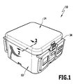
- FIG. 1 is a total provided with the reference numeral 10 sterile container, which can also be referred to as a sterile container, shown schematically. It comprises a trough-shaped container lower part 12 and a lid-shaped container upper part 14 for closing the container lower part 12. Walls of the container lower part 12 and of the container upper part 14 delimit in an in FIG. 1 shown closed position of the sterile container 10 a container interior 16th
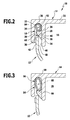
- a sealing device 18 For sealing the container interior 16 in the closed position, a sealing device 18 is used. It comprises a circumferential sealing element 20, which on the container base 12 or alternatively on the container top 14, as shown schematically in the FIGS. 2 and 3 shown, is arranged in a circumferential groove on the container 14 groove 22. Alternatively, a corresponding groove for receiving the sealing device 18 could also be provided on the container lower part 12.
- the sealing element 20 has a container upper part sealing section 24 with a container upper part sealing surface region 26 bearing against the upper part 14 of the container. Furthermore, the sealing element 20 comprises a container base sealing portion 28 with a container bottom sealing surface region 30 bearing against the container base 12.
- the groove 22 is defined by two parallel to each other, from a top wall 32 vertically projecting side walls 34 and 36, wherein the side wall 34, the container top 14 laterally limited laterally and slightly shorter than the slightly spaced from her side wall 36.
- a groove bottom 38 is in cross section semicircular and concavely curved in the direction of the container base 12 toward.
- the upper container sealing surface region 26 is flat and lies flat against a wall surface 40 of the side wall 36 which points in the direction of the side wall 34.
- An end section 42 of the container lower part 12, which points in the direction of the container upper part 14, has a wall-shaped design and has a flat end face 44 pointing in the direction of the groove bottom 38.
- the sealing element 20 has a pointing in the direction of the groove bottom 38 toward, in a basic position, as shown schematically in FIG. 3 shown, level and in a closed position, as shown schematically in FIG FIG. 2 represented, slightly convex curved contact surface 52.
- the sealing device 18 further comprises a biasing device 54, which has a biasing member 56 in the form of a self-contained, held in the groove 22 coil spring 58.
- the biasing member 56 is supported on the one hand substantially on the groove bottom 38 and on the other hand on the contact surface 52 from.
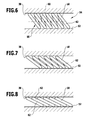
- the coil spring 58 is obliquely wound on a helix defined by her 60, so that individual turns 62 of the coil spring 58 is not substantially in a plane perpendicular to the helix 60, but relative to this already in a normal position of the coil spring 58, in which no external forces acting on these, are inclined at about 45 °. This is schematically in FIG. 6 shown.
- the biasing member 56 defines a leader longitudinal line 64 that corresponds to the helix 60.
- the biasing member 56 exerts a transversely, in particular perpendicular, force acting on the biasing member longitudinal line 64 on the Be bacheloreroberteildichtabites 24 and the Be bachelorerteildichtabites 28 from.
- the pretensioning element 56 abuts indirectly with respect to the container upper part sealing section 24 and the lower container sealing section 28 via the contact surface 52 with an outer surface 66 oriented transversely, in particular perpendicularly, to the pretensioning element longitudinal line 64.
- the coil spring 58 is integrally formed and closed in itself, so that therefore only a single biasing member 56 is provided. It would be conceivable to provide two or more biasing members 56 in the form of coil springs 58, whose free ends are connected to each other.
- biasing means 54 is partially covered or surrounded by the sealing element 20.
- the upper container sealing portion 24 is fixed, but movably connected to the container upper part 14.
- the arrangement could also be formed vice versa in that the container base sealing portion is firmly but movably connected to the container base 12.
- the biasing means 54 is thus arranged to apply a biasing force to the container bottom sealing portion 28 and the container top sealing portion 24.
- the container bottom sealing portion 28 and the container bottom 12 are arranged to be movable relative to each other.
- the container base 12 can be completely detached from the container base sealing portion 28.
- the upper container sealing portion is arranged to be movable relative to the upper container part 14.
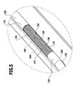
- FIG. 4 Schematically is in FIG. 4 an alternative embodiment of a sterile container in total provided with the reference numeral 110. It comprises a trough-shaped container lower part 112 and a substantially identically formed container upper part 114 for closing the container lower part 112. They in turn define a container interior 116 in a closed position.
- a sealing device 118 On the sealing surface 170 of the container base 112, a sealing device 118 is held. It includes a self-contained, tubular sealing member 120 which defines a circumferential, hollow and cavity defining a biasing means receptacle 172, in which a biasing means 154 comprising a biasing member longitudinal line 164 defining biasing member 156 is held in the form of a screw 160 defining coil spring 158.
- the sealing element 120 thus completely encloses the pretensioning device 154.
- the sealing element 120 in the form of a profile strand similar to the sealing element 120, which profile strand has a tubular basic shape, but a circumferential, lateral opening to the biasing device receptacle 172, through which opening the biasing member 156 can be inserted into the cavity 176.
- the sealing element 120 may be glued or welded to the sealing surface 170, for example. It is thus firmly connected to the container base 112 and holds the biasing means 154 in a defined manner in position. Alternatively, it would also be possible to arrange and fix the sealing device 118 in an analogous manner on the container upper part 114.
- the container upper part 114 is placed with its sealing surface 170 on the sealing element 120. Thereby, a tank top sealing portion 124 defining a tank top sealing surface area 126 is pressed against an outer surface 166 of the coil spring 158. Similarly, the outer surface 166 is also pressed against a lower container sealing portion 128 defining a lower container sealing surface portion 130.
- clamp-shaped closure elements 174 allow the container top 114 with a partial deflected biasing means 154 to hold in the closed position.
- the deformation of the coil spring 158 when closing the sterile container 110 is analogous to that in the FIGS. 6 to 8
- the helical spring 158 ensures that the container top sealing surface region 126 and the container bottom sealing surface region 130 permanently and securely abut the sealing surfaces 170 of the container bottom part 112 and the container top part 114.
- the coil springs 58 and 158 are preferably made of a metal, in particular alloys of copper and beryllium are particularly suitable.
- the sealing elements 20 and 120 are made of a plastic, for example by injection molding or extrusion. By providing the pretensioning device 54 or 154, the plastic, in particular also permanently, does not have to have any great elastic properties, so that in particular polytetrafluoroethylene is also suitable as material for producing the sealing elements 20 and 120.
- the sealing elements 20 and 120 may also be made of or contain an elastomer, for example rubber.
- Required biasing forces can be adjusted in a targeted manner by designing the biasing members 56 and 156, in particular by selecting appropriate materials, and dimensioning, for example, a diameter of the coil spring 58 and 158 and the wire material used to wind it.
Landscapes
- Health & Medical Sciences (AREA)
- Engineering & Computer Science (AREA)
- Life Sciences & Earth Sciences (AREA)
- Mechanical Engineering (AREA)
- Veterinary Medicine (AREA)
- Surgery (AREA)
- General Health & Medical Sciences (AREA)
- Public Health (AREA)
- Animal Behavior & Ethology (AREA)
- Epidemiology (AREA)
- Nuclear Medicine, Radiotherapy & Molecular Imaging (AREA)
- Food Science & Technology (AREA)
- Biomedical Technology (AREA)
- Heart & Thoracic Surgery (AREA)
- Medical Informatics (AREA)
- Molecular Biology (AREA)
- Closures For Containers (AREA)
- Packages (AREA)
- Closing Of Containers (AREA)
Applications Claiming Priority (1)
| Application Number | Priority Date | Filing Date | Title |
|---|---|---|---|
| DE102010036489A DE102010036489A1 (de) | 2010-07-19 | 2010-07-19 | Behälterunterteil und Behälteroberteil eines Sterilbehälters und Sterilbehälter |
Publications (3)
| Publication Number | Publication Date |
|---|---|
| EP2409663A2 true EP2409663A2 (fr) | 2012-01-25 |
| EP2409663A3 EP2409663A3 (fr) | 2015-08-12 |
| EP2409663B1 EP2409663B1 (fr) | 2019-05-15 |
Family
ID=44543049
Family Applications (1)
| Application Number | Title | Priority Date | Filing Date |
|---|---|---|---|
| EP11173708.6A Active EP2409663B1 (fr) | 2010-07-19 | 2011-07-12 | Parties inférieure et supérieure d'un contenant stérile et contenant stérile |
Country Status (3)
| Country | Link |
|---|---|
| US (1) | US8627972B2 (fr) |
| EP (1) | EP2409663B1 (fr) |
| DE (1) | DE102010036489A1 (fr) |
Families Citing this family (20)
| Publication number | Priority date | Publication date | Assignee | Title |
|---|---|---|---|---|
| DE102012215121A1 (de) * | 2012-08-24 | 2014-05-28 | Aesculap Ag | Zentrierhilfe für Behälterdeckel |
| US20140138384A1 (en) * | 2012-11-20 | 2014-05-22 | Angela O'Brien | Waterproof Crush Resistant Compartment |
| DE102016112885A1 (de) | 2016-07-13 | 2018-01-18 | Aesculap Ag | Medizinischer Container mit schräger Deckeldichtung |
| US11976498B2 (en) | 2017-06-12 | 2024-05-07 | Yeti Coolers, Llc | Container and latching system |
| US11685573B2 (en) | 2017-06-12 | 2023-06-27 | Yeti Coolers, Llc | Carry strap for container |
| AU201717615S (en) | 2017-06-12 | 2018-01-15 | Yeti Coolers | Container |
| WO2018231826A1 (fr) | 2017-06-12 | 2018-12-20 | Yeti Coolers, Llc | Contenant et système de verrouillage |
| US12108853B2 (en) | 2019-01-06 | 2024-10-08 | Yeti Coolers, Llc | Luggage system |
| USD907445S1 (en) | 2018-12-11 | 2021-01-12 | Yeti Coolers, Llc | Container accessories |
| USD904829S1 (en) | 2018-12-11 | 2020-12-15 | Yeti Coolers, Llc | Container accessories |
| MX2021008199A (es) | 2019-01-06 | 2021-11-12 | Yeti Coolers Llc | Sistema de equipaje. |
| US12225993B2 (en) | 2019-01-06 | 2025-02-18 | Yeti Coolers, Llc | Luggage system |
| DE102020104606A1 (de) | 2020-02-21 | 2021-08-26 | Aesculap Ag | Sterilbehälter |
| USD954436S1 (en) | 2020-06-30 | 2022-06-14 | Yeti Coolers, Llc | Luggage |
| USD963344S1 (en) | 2020-06-30 | 2022-09-13 | Yeti Coolers, Llc | Luggage |
| USD961926S1 (en) | 2020-06-30 | 2022-08-30 | Yeti Coolers, Llc | Luggage |
| USD951643S1 (en) | 2020-06-30 | 2022-05-17 | Yeti Coolers, Llc | Luggage |
| USD985937S1 (en) | 2020-12-16 | 2023-05-16 | Yeti Coolers, Llc | Container |
| USD960648S1 (en) | 2020-12-16 | 2022-08-16 | Yeti Coolers, Llc | Container accessory |
| USD994438S1 (en) | 2020-12-16 | 2023-08-08 | Yeti Coolers, Llc | Container |
Family Cites Families (13)
| Publication number | Priority date | Publication date | Assignee | Title |
|---|---|---|---|---|
| DE1908434U (de) * | 1964-11-05 | 1965-01-14 | Eisenwerk Streuber & Lohmann H | Schraubkappe mit eingelegtem dichtungsring. |
| DE1908434C2 (de) | 1969-02-20 | 1971-03-04 | Kostal Fa Leopold | Elektrischer Umschalter |
| DE3338371A1 (de) | 1983-10-21 | 1985-05-09 | Karl Leibinger Medizintechnik GmbH & Co, 7202 Mühlheim | Sterilisierbehaelter |
| DE3500026C2 (de) * | 1983-10-21 | 1994-01-27 | Leibinger Medizintech | Sterilisierbehälter |
| US4919888A (en) * | 1988-09-06 | 1990-04-24 | Instrumed, Inc. | Seals and method of sealing for a sterilization container system |
| US5641065A (en) * | 1995-06-22 | 1997-06-24 | Paragon Group Of Plastics Companies, Inc. | Medical instrument soaking, transporting and storage container |
| DE19755532C2 (de) * | 1997-12-13 | 2001-07-12 | Aesculap Ag & Co Kg | Sterilcontainer für medizinische Zwecke |
| US6591998B2 (en) * | 2000-12-21 | 2003-07-15 | Sulzer Carbomedics Inc. | Leakproof container for implantable prosthetic device |
| EP1405799A4 (fr) * | 2001-07-11 | 2004-12-29 | Mitsubishi Heavy Ind Ltd | Structure de joint d'etancheite d'un recipient et filtre d'evacuation |
| DE20213526U1 (de) * | 2002-08-27 | 2002-11-07 | Aesculap AG & Co. KG, 78532 Tuttlingen | Sterilbehälter und Deckel für einen Sterilbehälter |
| DE102004020804A1 (de) * | 2004-04-16 | 2005-11-10 | Aesculap Ag & Co. Kg | Sterilbehälter |
| DE202009002968U1 (de) * | 2009-02-20 | 2009-05-20 | Aesculap Ag | Sterilisierbehälter |
| DE202009004204U1 (de) * | 2009-03-18 | 2009-06-18 | Aesculap Ag | Sterilbehälter |
-
2010
- 2010-07-19 DE DE102010036489A patent/DE102010036489A1/de not_active Ceased
-
2011
- 2011-07-07 US US13/135,596 patent/US8627972B2/en active Active
- 2011-07-12 EP EP11173708.6A patent/EP2409663B1/fr active Active
Non-Patent Citations (1)
| Title |
|---|
| None |
Also Published As
| Publication number | Publication date |
|---|---|
| US20120012580A1 (en) | 2012-01-19 |
| EP2409663B1 (fr) | 2019-05-15 |
| US8627972B2 (en) | 2014-01-14 |
| DE102010036489A1 (de) | 2012-01-19 |
| EP2409663A3 (fr) | 2015-08-12 |
Similar Documents
| Publication | Publication Date | Title |
|---|---|---|
| EP2409663B1 (fr) | Parties inférieure et supérieure d'un contenant stérile et contenant stérile | |
| EP0720681B1 (fr) | Tuyau flexible d'injection pour joints de constructions en beton | |
| EP2079895B1 (fr) | Profilé extrudé à cavité pour porte ou fenêtre | |
| EP1392390B1 (fr) | Ensemble soupape pour des instruments chirurgicaux et lanterne de soupape recevant l'ensemble soupape | |
| EP3202346B1 (fr) | Douille de trocart, système de trocart et procédé de fabrication d'une douille de trocart | |
| WO2011029838A1 (fr) | Joint annulaire pour un organe de fermeture d'une soupape et ensemble d'étanchéité pour ledit joint annulaire | |
| DE102015010532A1 (de) | Filtervorrichtung nebst Filterelement | |
| EP2181275B1 (fr) | Tube protecteur pour ensemble piston-cylindre | |
| DE102012100583B4 (de) | Einsatz für Zellkulturen | |
| DE202010008107U1 (de) | Behälterunterteil und Behälteroberteil eines Sterilbehälters und Sterilbehälter | |
| EP3025080A1 (fr) | Dispositif d'étanchéité par pression et corps formant presse | |
| EP3188919B2 (fr) | Dispositif d'étanchéité pour porte, système d'étanchéité pour porte et battant de porte pour véhicule ferroviaire | |
| EP2016854A1 (fr) | Dispositif d'application destiné à l'application d'un support liquide | |
| DE102009042164A1 (de) | Ringdichtung für ein Schließglied eines Ventils sowie Dichtungsanordnung mit einer solchen Ringdichtung | |
| DE202006003678U1 (de) | Flachdichtung, insbesondere Zylinderkopfdichtung | |
| EP3875398B1 (fr) | Fermeture destinée à la fermeture étanche d'un contenant rempli d'une substance, récipient comprenant un contenant et une fermeture, et procédé pour remplir un récipient d'une substance | |
| EP2510953B1 (fr) | Conteneur de stérilisation avec deux joint et support de joint | |
| DE10035378B4 (de) | Dichtungsanordnung für eine schwellenlose Türe | |
| EP1920727B1 (fr) | Joint hermétique torsadé | |
| DE2313482A1 (de) | Verschlusskappe fuer tuben | |
| WO2014015855A2 (fr) | Outil d'insertion | |
| DE19961725A1 (de) | Trinkhalm zum Trinken von Getränken aus Trinkcontainern | |
| DE4433160A1 (de) | Behälterverschluß mit Kindersicherung | |
| DE202009004204U1 (de) | Sterilbehälter | |
| AT510343A1 (de) | Vorrichtung zur aufnahme oder entnahme von flüssigkeit |
Legal Events
| Date | Code | Title | Description |
|---|---|---|---|
| AK | Designated contracting states |
Kind code of ref document: A2 Designated state(s): AL AT BE BG CH CY CZ DE DK EE ES FI FR GB GR HR HU IE IS IT LI LT LU LV MC MK MT NL NO PL PT RO RS SE SI SK SM TR |
|
| AX | Request for extension of the european patent |
Extension state: BA ME |
|
| PUAI | Public reference made under article 153(3) epc to a published international application that has entered the european phase |
Free format text: ORIGINAL CODE: 0009012 |
|
| RIN1 | Information on inventor provided before grant (corrected) |
Inventor name: THOMAS, STEFAN |
|
| PUAL | Search report despatched |
Free format text: ORIGINAL CODE: 0009013 |
|
| RIC1 | Information provided on ipc code assigned before grant |
Ipc: A61B 19/02 20060101AFI20150622BHEP |
|
| AK | Designated contracting states |
Kind code of ref document: A3 Designated state(s): AL AT BE BG CH CY CZ DE DK EE ES FI FR GB GR HR HU IE IS IT LI LT LU LV MC MK MT NL NO PL PT RO RS SE SI SK SM TR |
|
| AX | Request for extension of the european patent |
Extension state: BA ME |
|
| RIC1 | Information provided on ipc code assigned before grant |
Ipc: A61B 19/02 20060101AFI20150708BHEP |
|
| 17P | Request for examination filed |
Effective date: 20160209 |
|
| RBV | Designated contracting states (corrected) |
Designated state(s): AL AT BE BG CH CY CZ DE DK EE ES FI FR GB GR HR HU IE IS IT LI LT LU LV MC MK MT NL NO PL PT RO RS SE SI SK SM TR |
|
| REG | Reference to a national code |
Ref country code: DE Ref legal event code: R079 Ref document number: 502011015714 Country of ref document: DE Free format text: PREVIOUS MAIN CLASS: A61B0019020000 Ipc: A61B0050000000 |
|
| GRAP | Despatch of communication of intention to grant a patent |
Free format text: ORIGINAL CODE: EPIDOSNIGR1 |
|
| STAA | Information on the status of an ep patent application or granted ep patent |
Free format text: STATUS: GRANT OF PATENT IS INTENDED |
|
| RIC1 | Information provided on ipc code assigned before grant |
Ipc: A61B 50/00 20160101AFI20180820BHEP |
|
| INTG | Intention to grant announced |
Effective date: 20180925 |
|
| GRAJ | Information related to disapproval of communication of intention to grant by the applicant or resumption of examination proceedings by the epo deleted |
Free format text: ORIGINAL CODE: EPIDOSDIGR1 |
|
| STAA | Information on the status of an ep patent application or granted ep patent |
Free format text: STATUS: REQUEST FOR EXAMINATION WAS MADE |
|
| GRAP | Despatch of communication of intention to grant a patent |
Free format text: ORIGINAL CODE: EPIDOSNIGR1 |
|
| STAA | Information on the status of an ep patent application or granted ep patent |
Free format text: STATUS: GRANT OF PATENT IS INTENDED |
|
| INTC | Intention to grant announced (deleted) | ||
| GRAJ | Information related to disapproval of communication of intention to grant by the applicant or resumption of examination proceedings by the epo deleted |
Free format text: ORIGINAL CODE: EPIDOSDIGR1 |
|
| STAA | Information on the status of an ep patent application or granted ep patent |
Free format text: STATUS: REQUEST FOR EXAMINATION WAS MADE |
|
| INTG | Intention to grant announced |
Effective date: 20190214 |
|
| GRAP | Despatch of communication of intention to grant a patent |
Free format text: ORIGINAL CODE: EPIDOSNIGR1 |
|
| STAA | Information on the status of an ep patent application or granted ep patent |
Free format text: STATUS: GRANT OF PATENT IS INTENDED |
|
| GRAS | Grant fee paid |
Free format text: ORIGINAL CODE: EPIDOSNIGR3 |
|
| INTC | Intention to grant announced (deleted) | ||
| GRAA | (expected) grant |
Free format text: ORIGINAL CODE: 0009210 |
|
| STAA | Information on the status of an ep patent application or granted ep patent |
Free format text: STATUS: THE PATENT HAS BEEN GRANTED |
|
| INTG | Intention to grant announced |
Effective date: 20190327 |
|
| AK | Designated contracting states |
Kind code of ref document: B1 Designated state(s): AL AT BE BG CH CY CZ DE DK EE ES FI FR GB GR HR HU IE IS IT LI LT LU LV MC MK MT NL NO PL PT RO RS SE SI SK SM TR |
|
| REG | Reference to a national code |
Ref country code: CH Ref legal event code: EP Ref country code: GB Ref legal event code: FG4D Free format text: NOT ENGLISH |
|
| REG | Reference to a national code |
Ref country code: DE Ref legal event code: R096 Ref document number: 502011015714 Country of ref document: DE |
|
| REG | Reference to a national code |
Ref country code: IE Ref legal event code: FG4D Free format text: LANGUAGE OF EP DOCUMENT: GERMAN |
|
| REG | Reference to a national code |
Ref country code: NL Ref legal event code: MP Effective date: 20190515 |
|
| REG | Reference to a national code |
Ref country code: LT Ref legal event code: MG4D |
|
| PG25 | Lapsed in a contracting state [announced via postgrant information from national office to epo] |
Ref country code: AL Free format text: LAPSE BECAUSE OF FAILURE TO SUBMIT A TRANSLATION OF THE DESCRIPTION OR TO PAY THE FEE WITHIN THE PRESCRIBED TIME-LIMIT Effective date: 20190515 Ref country code: FI Free format text: LAPSE BECAUSE OF FAILURE TO SUBMIT A TRANSLATION OF THE DESCRIPTION OR TO PAY THE FEE WITHIN THE PRESCRIBED TIME-LIMIT Effective date: 20190515 Ref country code: SE Free format text: LAPSE BECAUSE OF FAILURE TO SUBMIT A TRANSLATION OF THE DESCRIPTION OR TO PAY THE FEE WITHIN THE PRESCRIBED TIME-LIMIT Effective date: 20190515 Ref country code: PT Free format text: LAPSE BECAUSE OF FAILURE TO SUBMIT A TRANSLATION OF THE DESCRIPTION OR TO PAY THE FEE WITHIN THE PRESCRIBED TIME-LIMIT Effective date: 20190915 Ref country code: NO Free format text: LAPSE BECAUSE OF FAILURE TO SUBMIT A TRANSLATION OF THE DESCRIPTION OR TO PAY THE FEE WITHIN THE PRESCRIBED TIME-LIMIT Effective date: 20190815 Ref country code: NL Free format text: LAPSE BECAUSE OF FAILURE TO SUBMIT A TRANSLATION OF THE DESCRIPTION OR TO PAY THE FEE WITHIN THE PRESCRIBED TIME-LIMIT Effective date: 20190515 Ref country code: HR Free format text: LAPSE BECAUSE OF FAILURE TO SUBMIT A TRANSLATION OF THE DESCRIPTION OR TO PAY THE FEE WITHIN THE PRESCRIBED TIME-LIMIT Effective date: 20190515 Ref country code: LT Free format text: LAPSE BECAUSE OF FAILURE TO SUBMIT A TRANSLATION OF THE DESCRIPTION OR TO PAY THE FEE WITHIN THE PRESCRIBED TIME-LIMIT Effective date: 20190515 Ref country code: ES Free format text: LAPSE BECAUSE OF FAILURE TO SUBMIT A TRANSLATION OF THE DESCRIPTION OR TO PAY THE FEE WITHIN THE PRESCRIBED TIME-LIMIT Effective date: 20190515 |
|
| PG25 | Lapsed in a contracting state [announced via postgrant information from national office to epo] |
Ref country code: LV Free format text: LAPSE BECAUSE OF FAILURE TO SUBMIT A TRANSLATION OF THE DESCRIPTION OR TO PAY THE FEE WITHIN THE PRESCRIBED TIME-LIMIT Effective date: 20190515 Ref country code: RS Free format text: LAPSE BECAUSE OF FAILURE TO SUBMIT A TRANSLATION OF THE DESCRIPTION OR TO PAY THE FEE WITHIN THE PRESCRIBED TIME-LIMIT Effective date: 20190515 Ref country code: BG Free format text: LAPSE BECAUSE OF FAILURE TO SUBMIT A TRANSLATION OF THE DESCRIPTION OR TO PAY THE FEE WITHIN THE PRESCRIBED TIME-LIMIT Effective date: 20190815 Ref country code: GR Free format text: LAPSE BECAUSE OF FAILURE TO SUBMIT A TRANSLATION OF THE DESCRIPTION OR TO PAY THE FEE WITHIN THE PRESCRIBED TIME-LIMIT Effective date: 20190816 |
|
| PG25 | Lapsed in a contracting state [announced via postgrant information from national office to epo] |
Ref country code: CZ Free format text: LAPSE BECAUSE OF FAILURE TO SUBMIT A TRANSLATION OF THE DESCRIPTION OR TO PAY THE FEE WITHIN THE PRESCRIBED TIME-LIMIT Effective date: 20190515 Ref country code: SK Free format text: LAPSE BECAUSE OF FAILURE TO SUBMIT A TRANSLATION OF THE DESCRIPTION OR TO PAY THE FEE WITHIN THE PRESCRIBED TIME-LIMIT Effective date: 20190515 Ref country code: DK Free format text: LAPSE BECAUSE OF FAILURE TO SUBMIT A TRANSLATION OF THE DESCRIPTION OR TO PAY THE FEE WITHIN THE PRESCRIBED TIME-LIMIT Effective date: 20190515 Ref country code: EE Free format text: LAPSE BECAUSE OF FAILURE TO SUBMIT A TRANSLATION OF THE DESCRIPTION OR TO PAY THE FEE WITHIN THE PRESCRIBED TIME-LIMIT Effective date: 20190515 Ref country code: RO Free format text: LAPSE BECAUSE OF FAILURE TO SUBMIT A TRANSLATION OF THE DESCRIPTION OR TO PAY THE FEE WITHIN THE PRESCRIBED TIME-LIMIT Effective date: 20190515 |
|
| REG | Reference to a national code |
Ref country code: DE Ref legal event code: R097 Ref document number: 502011015714 Country of ref document: DE |
|
| PG25 | Lapsed in a contracting state [announced via postgrant information from national office to epo] |
Ref country code: IT Free format text: LAPSE BECAUSE OF FAILURE TO SUBMIT A TRANSLATION OF THE DESCRIPTION OR TO PAY THE FEE WITHIN THE PRESCRIBED TIME-LIMIT Effective date: 20190515 Ref country code: MC Free format text: LAPSE BECAUSE OF FAILURE TO SUBMIT A TRANSLATION OF THE DESCRIPTION OR TO PAY THE FEE WITHIN THE PRESCRIBED TIME-LIMIT Effective date: 20190515 Ref country code: SM Free format text: LAPSE BECAUSE OF FAILURE TO SUBMIT A TRANSLATION OF THE DESCRIPTION OR TO PAY THE FEE WITHIN THE PRESCRIBED TIME-LIMIT Effective date: 20190515 |
|
| REG | Reference to a national code |
Ref country code: CH Ref legal event code: PL |
|
| PLBE | No opposition filed within time limit |
Free format text: ORIGINAL CODE: 0009261 |
|
| STAA | Information on the status of an ep patent application or granted ep patent |
Free format text: STATUS: NO OPPOSITION FILED WITHIN TIME LIMIT |
|
| PG25 | Lapsed in a contracting state [announced via postgrant information from national office to epo] |
Ref country code: TR Free format text: LAPSE BECAUSE OF FAILURE TO SUBMIT A TRANSLATION OF THE DESCRIPTION OR TO PAY THE FEE WITHIN THE PRESCRIBED TIME-LIMIT Effective date: 20190515 |
|
| REG | Reference to a national code |
Ref country code: BE Ref legal event code: MM Effective date: 20190731 |
|
| 26N | No opposition filed |
Effective date: 20200218 |
|
| PG25 | Lapsed in a contracting state [announced via postgrant information from national office to epo] |
Ref country code: PL Free format text: LAPSE BECAUSE OF FAILURE TO SUBMIT A TRANSLATION OF THE DESCRIPTION OR TO PAY THE FEE WITHIN THE PRESCRIBED TIME-LIMIT Effective date: 20190515 |
|
| PG25 | Lapsed in a contracting state [announced via postgrant information from national office to epo] |
Ref country code: SI Free format text: LAPSE BECAUSE OF FAILURE TO SUBMIT A TRANSLATION OF THE DESCRIPTION OR TO PAY THE FEE WITHIN THE PRESCRIBED TIME-LIMIT Effective date: 20190515 Ref country code: LI Free format text: LAPSE BECAUSE OF NON-PAYMENT OF DUE FEES Effective date: 20190731 Ref country code: CH Free format text: LAPSE BECAUSE OF NON-PAYMENT OF DUE FEES Effective date: 20190731 Ref country code: LU Free format text: LAPSE BECAUSE OF NON-PAYMENT OF DUE FEES Effective date: 20190712 Ref country code: BE Free format text: LAPSE BECAUSE OF NON-PAYMENT OF DUE FEES Effective date: 20190731 |
|
| PG25 | Lapsed in a contracting state [announced via postgrant information from national office to epo] |
Ref country code: IE Free format text: LAPSE BECAUSE OF NON-PAYMENT OF DUE FEES Effective date: 20190712 |
|
| REG | Reference to a national code |
Ref country code: AT Ref legal event code: MM01 Ref document number: 1132519 Country of ref document: AT Kind code of ref document: T Effective date: 20190712 |
|
| PG25 | Lapsed in a contracting state [announced via postgrant information from national office to epo] |
Ref country code: AT Free format text: LAPSE BECAUSE OF NON-PAYMENT OF DUE FEES Effective date: 20190712 |
|
| PG25 | Lapsed in a contracting state [announced via postgrant information from national office to epo] |
Ref country code: CY Free format text: LAPSE BECAUSE OF FAILURE TO SUBMIT A TRANSLATION OF THE DESCRIPTION OR TO PAY THE FEE WITHIN THE PRESCRIBED TIME-LIMIT Effective date: 20190515 |
|
| PG25 | Lapsed in a contracting state [announced via postgrant information from national office to epo] |
Ref country code: IS Free format text: LAPSE BECAUSE OF FAILURE TO SUBMIT A TRANSLATION OF THE DESCRIPTION OR TO PAY THE FEE WITHIN THE PRESCRIBED TIME-LIMIT Effective date: 20190915 |
|
| PG25 | Lapsed in a contracting state [announced via postgrant information from national office to epo] |
Ref country code: HU Free format text: LAPSE BECAUSE OF FAILURE TO SUBMIT A TRANSLATION OF THE DESCRIPTION OR TO PAY THE FEE WITHIN THE PRESCRIBED TIME-LIMIT; INVALID AB INITIO Effective date: 20110712 Ref country code: MT Free format text: LAPSE BECAUSE OF FAILURE TO SUBMIT A TRANSLATION OF THE DESCRIPTION OR TO PAY THE FEE WITHIN THE PRESCRIBED TIME-LIMIT Effective date: 20190515 |
|
| PG25 | Lapsed in a contracting state [announced via postgrant information from national office to epo] |
Ref country code: MK Free format text: LAPSE BECAUSE OF FAILURE TO SUBMIT A TRANSLATION OF THE DESCRIPTION OR TO PAY THE FEE WITHIN THE PRESCRIBED TIME-LIMIT Effective date: 20190515 |
|
| P01 | Opt-out of the competence of the unified patent court (upc) registered |
Effective date: 20230926 |
|
| PGFP | Annual fee paid to national office [announced via postgrant information from national office to epo] |
Ref country code: DE Payment date: 20250722 Year of fee payment: 15 |
|
| PGFP | Annual fee paid to national office [announced via postgrant information from national office to epo] |
Ref country code: GB Payment date: 20250724 Year of fee payment: 15 |
|
| PGFP | Annual fee paid to national office [announced via postgrant information from national office to epo] |
Ref country code: FR Payment date: 20250723 Year of fee payment: 15 |